Assignment
Add an output device to a microcontroller board you've designed and program it to do something
Machines
Trotec Speedy 100
Soldering Heat Gun
Software
Adobe Illustrator CS6
Arduino IDE
Sublime Text
Materials
Antistatic table, Tweezers,
Solder Paste, 1/32 Milling Cutter,
Copper Board, Ferric Perchloride,
Solvent, Spray Paint
Electronic Components
10 pin LCD connector
1 ATtiny 44
6 pin ISP connector
4 pin power connector
1 Xtal Resonator 20 MHz
1 Resistor 1K
1 Resistor 10K
1 Resistor 100K
1 IC Regulator 5V
1 Capacitor 1uF
LCD
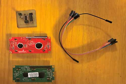
The LCDs have a parallel interface, meaning that the microcontroller has to manipulate several interface pins at once to control the display. The interface consists of the following pins:
A register select (RS) pin that controls where in the LCD's memory you're writing data to. You can select either the data register, which holds what goes on the screen, or an instruction register, which is where the LCD's controller looks for instructions on what to do next.
A Read/Write (R/W) pin that selects reading mode or writing mode
An Enable pin that enables writing to the registers
8 data pins (D0 -D7). The states of these pins (high or low) are the bits that you're writing to a register when you write, or the values you're reading when you read.
There's also a display constrast pin (Vo), power supply pins (+5V and Gnd) and LED Backlight (Bklt+ and BKlt-) pins that you can use to power the LCD, control the display contrast, and turn on and off the LED backlight, respectively.
The process of controlling the display involves putting the data that form the image of what you want to display into the data registers, then putting instructions in the instruction register. The LiquidCrystal Library simplifies this for you so you don't need to know the low-level instructions.
The Hitachi-compatible LCDs can be controlled in two modes: 4-bit or 8-bit. The 4-bit mode requires seven I/O pins from the Arduino, while the 8-bit mode requires 11 pins. For displaying text on the screen, you can do most everything in 4-bit mode, so example shows how to control a 2x16 LCD in 4-bit mode.
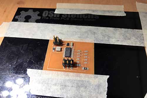
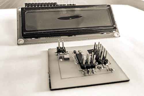
Creating the PCB
Guatemalan architect with specialization in urban design and planning. Consultant for mobility and territorial planning for the initiative of emerging and sustainable cities of the Inter-American Development Bank ICES QUETZALTENANGO. ICES uses a comprehensive and interdisciplinary approach to identify, organize and prioritize urban interventions to address the main obstacles to sustainable growth in the emerging cities of Latin America and the Caribbean.
Founder and director of La Granja Fab Lab first lab in Guatemala, a digital fabrication laboratory based in Quetzaltenango, which It is dedicated to research and experimentation of social innovation projects to provide local solutions in context.
Professor of architecture and urbanism at CUNOC -Centro Universitario de Occidente-Recent Works.
Interested in participating in Fab LAT, and in the projects Fab City and Fab Kids
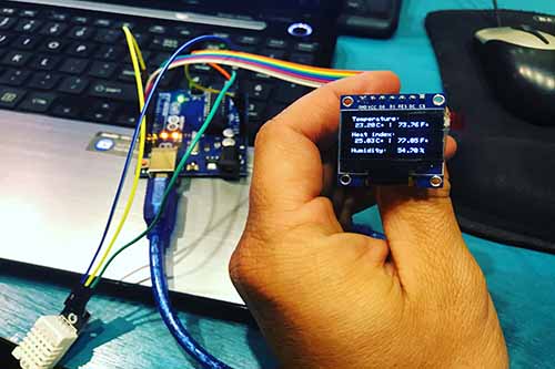
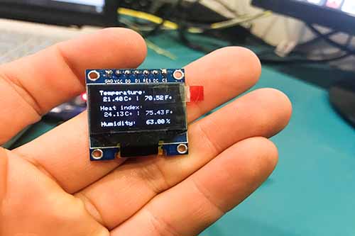
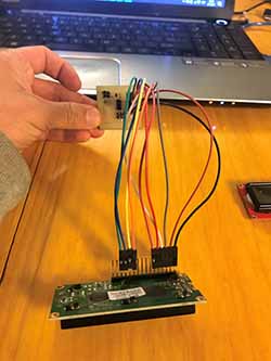
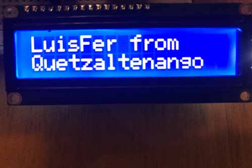
Workflow - Connecting PCB to LCD
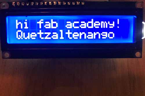
Extra for the Final Project