
The purpose of this assignment is make an in-circuit programmer by milling the PCB, then optionally trying other processes. We started with the basic knowledge of Arduino and the programming, we made 6 example exercises to confirm its respective operation. Then using the EAGLE platform, we make an example of a scheme and then generate the board to produce the circuit and its respective programming
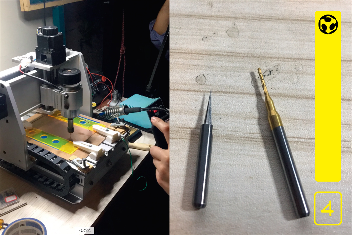
copper board
drill bits
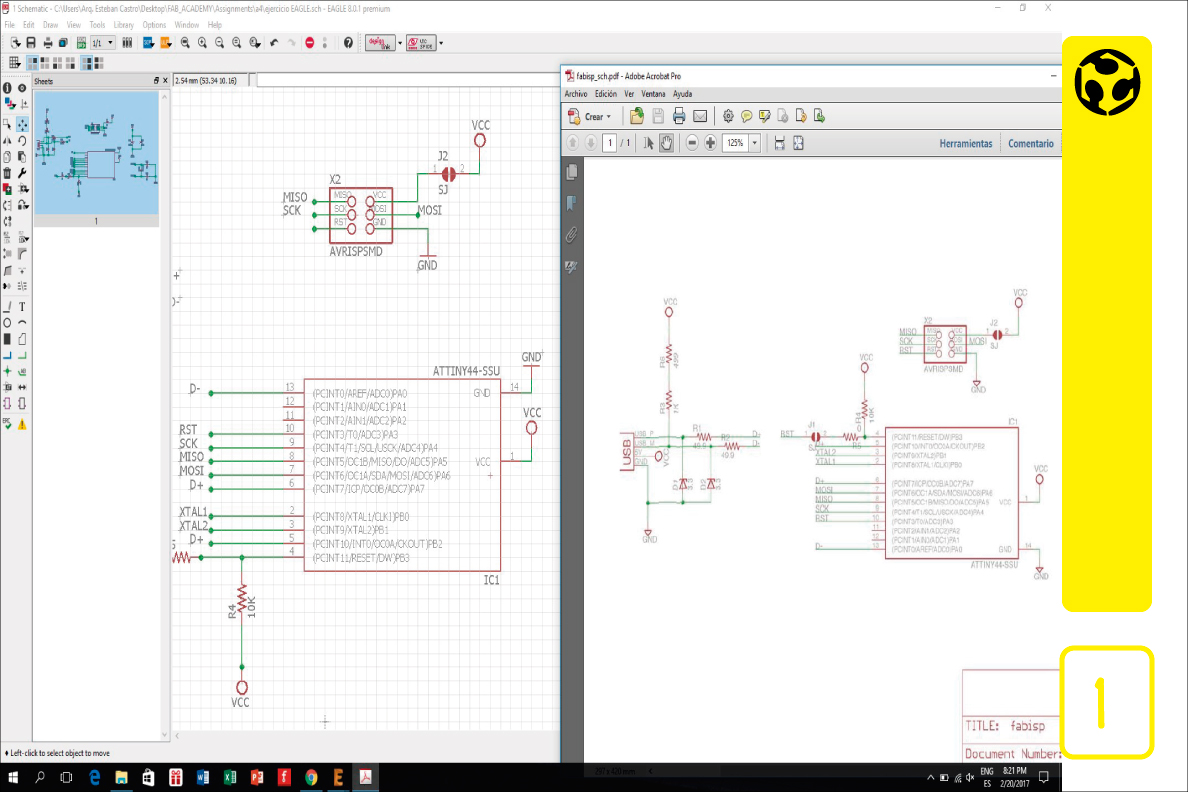
1. We developed the scheme in the EAGLE platform to later form the board (fabisp).
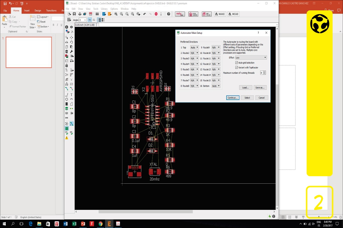
2. We use the autorouting tool.
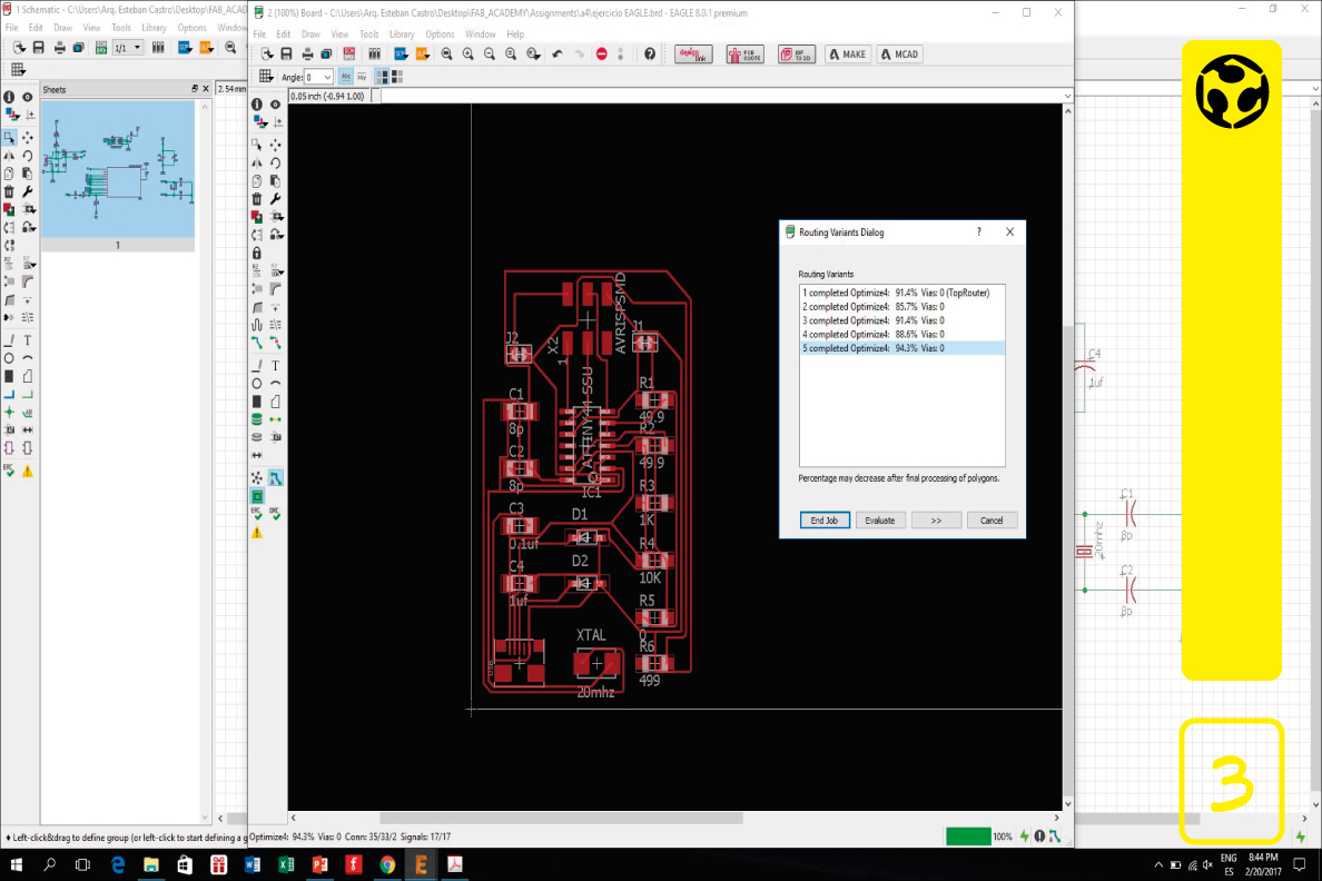
3. We create the board and select the schematic with greater optimization.
4. ELECTRONIC PRODUCTION
Our machine has the following technical specifications:
Maximum working stroke: XYZ = 200 * 300 * 45mm
Overall dimensions: 520 × 400 × 370mm
Working table size: 440 × 240mm
Engraving speed: 300-3000mm / min
Control communication interface: 25-pin parallel port
Control software: MACH3
Tool path format: G code / .nc / .ncc / .tab / .txt
2 drills we use for the project
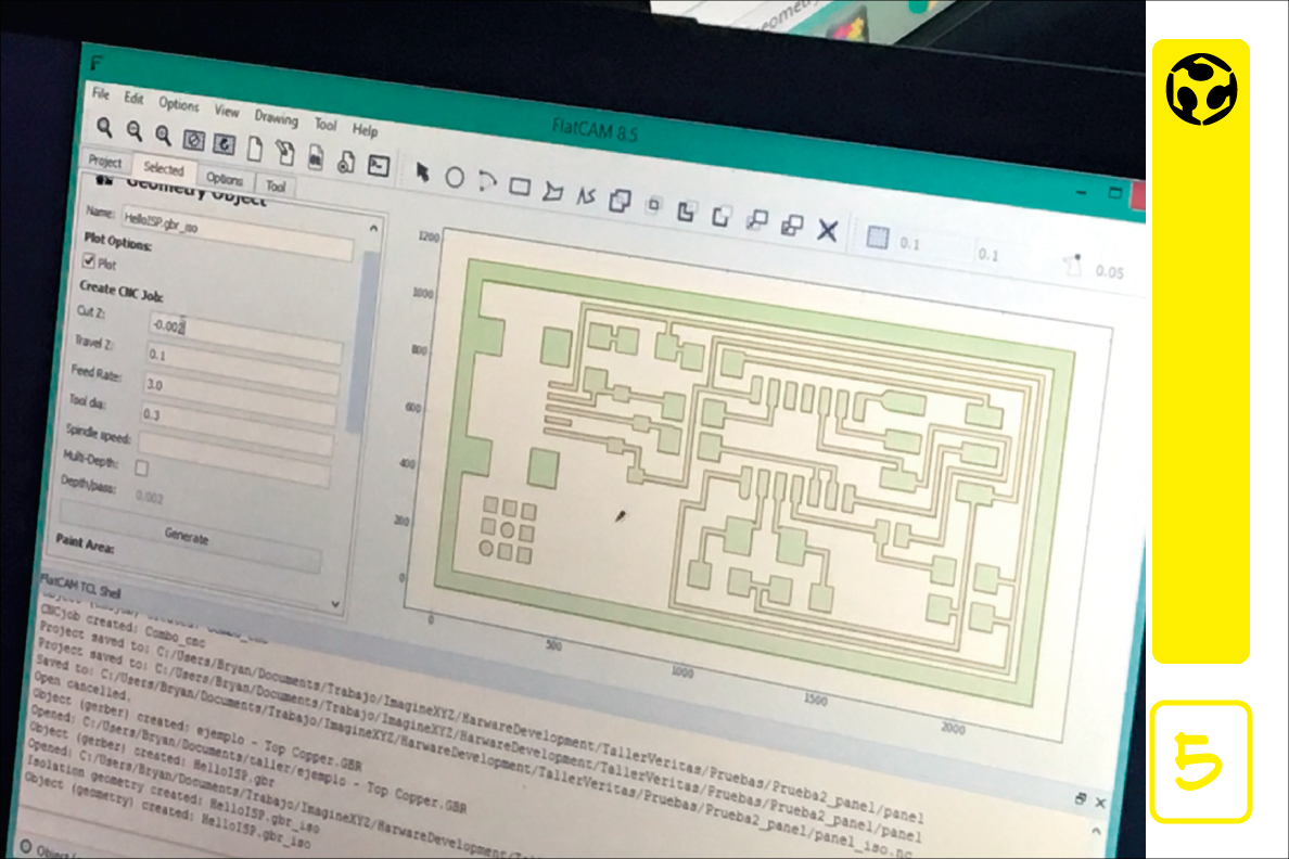
5. 3 files are necesary for to complete the cut task.
The first is the top traces (.sol), that describes the shape of the traces and pads on the top side of the PCB. The bottom traces is an optional files if your PCB is one-sided, but necesary if is dual-sided.
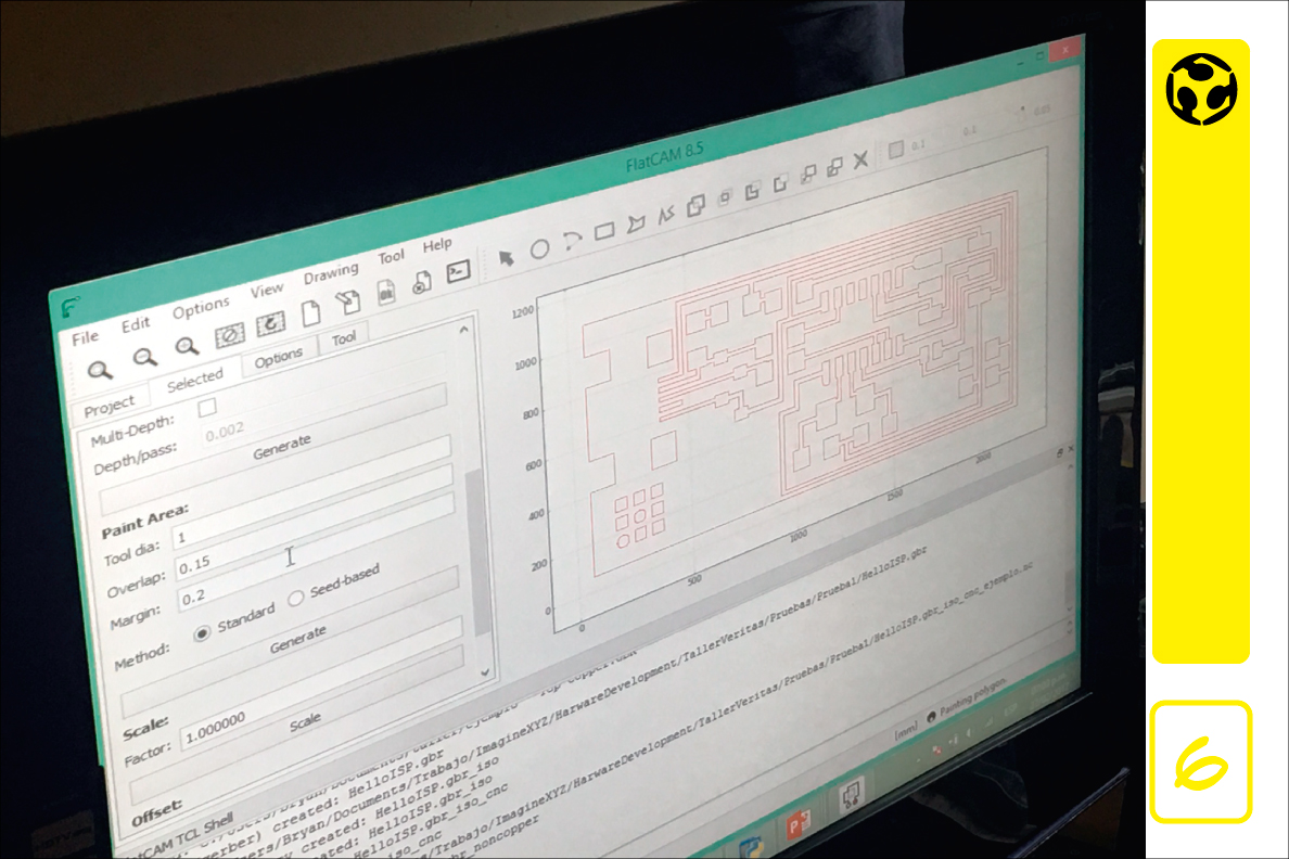
6. The second is the outline (.plc), that describes the outer dimension of the board.
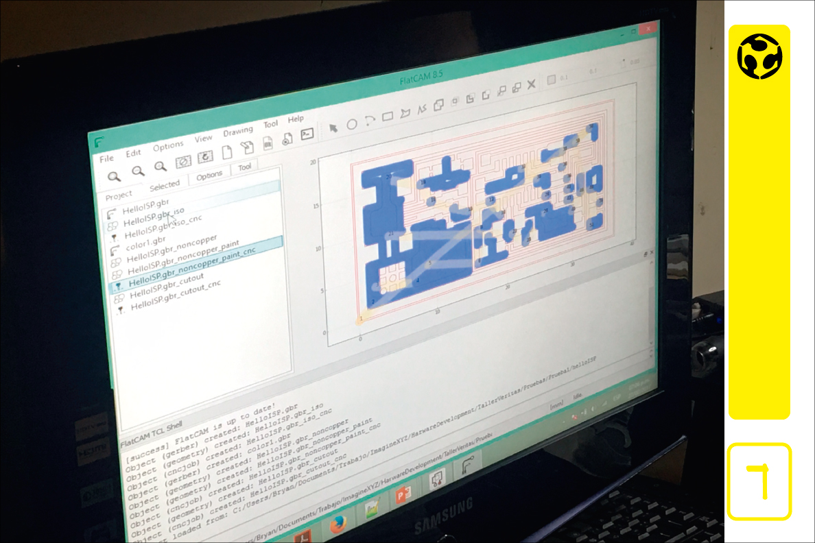
7. The third is for the holes (.drd), that describes the location and size of the PCB’s holes and vias.
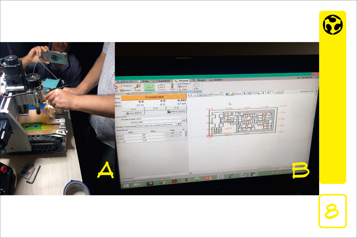
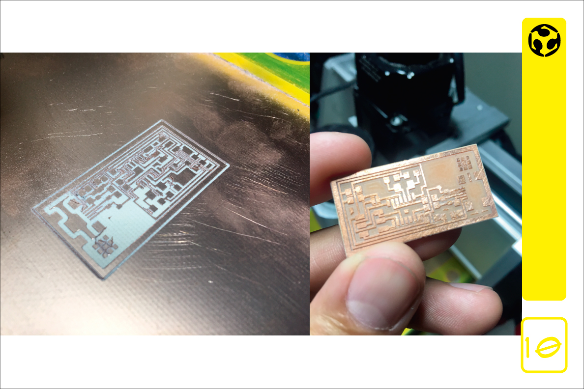
8. A) To start, adjustments are made to the copper plate and the heights are checked at different points on the plate.
B) Once the plate is clamped and aligned, a software called bCNC is used, which interprets the previously created files and sends the gcode to the machine.
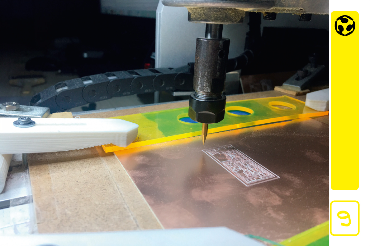
9. For security reasons is important to use protective glasses and dont touch the plate while the machine is cutting.
10. We are ready to solder the electronic components
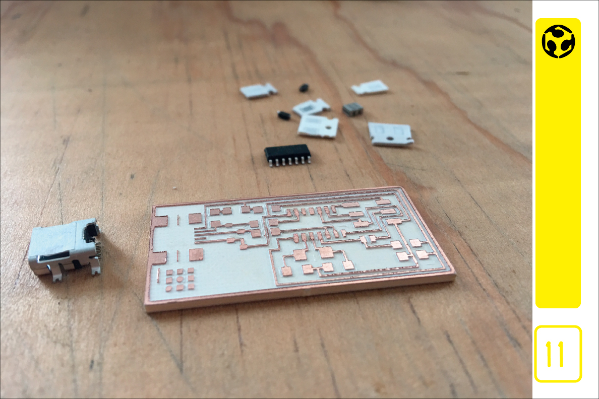
11. I select all the electronic components and prepare them to weld them to the copper plate.
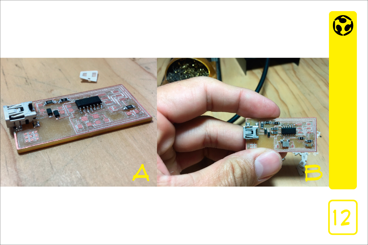
12. A. Welding process.
B. This way the components are welded to the copper plate, is almost finished.
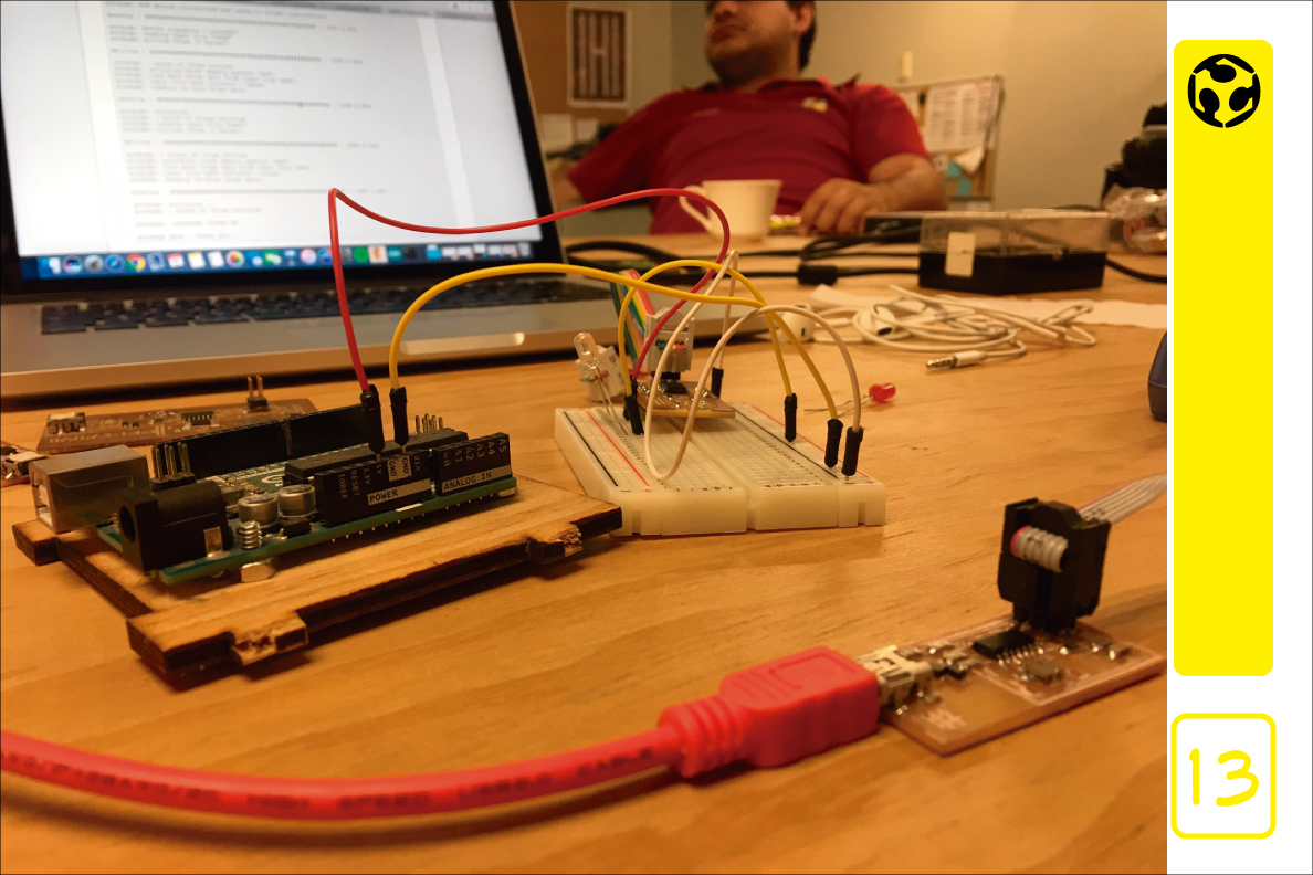
13. Once the plate is ready, we connect it to the arduino for its programming and then perform the test.
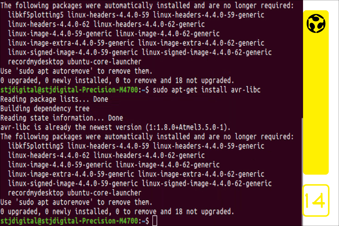
14. Installing software and libraries
apt-get install flex byacc bison gcc
libusb-dev avrdude
apt-get install gcc-avr
apt-get install avr-libc
apt-get install libc6-dev
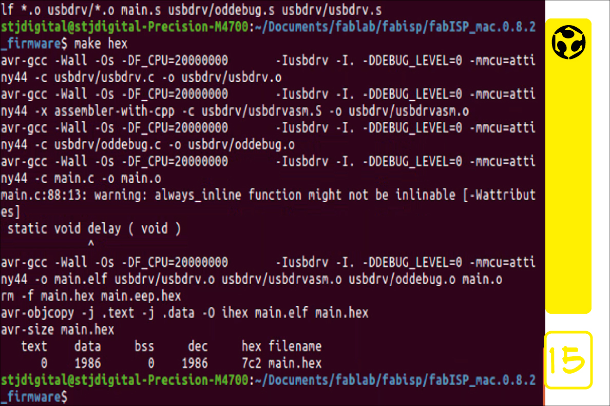
15. Programing FabISP
We are ready to connect to AVRISP Programming and computer. Then in the terminal of U buntu start the steps for programming.
make clean
make hex
make fuse
make program
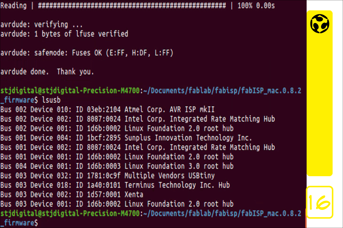
16. FabISP is ready
NOTE: All the programming was done from linux operating system.