This week we are going to learn how use a CNC Router Machine, its control software and the G-Code Generator
Machines
CNC Router
Materials
9mm MDF
1/4'' Milling Cutter
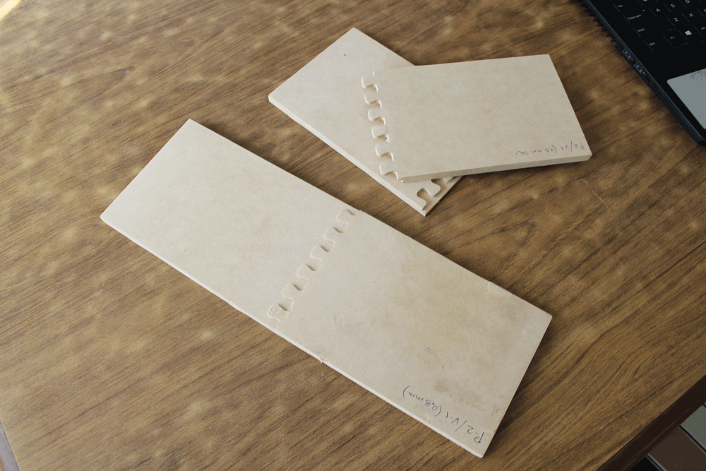
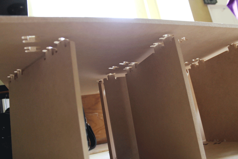
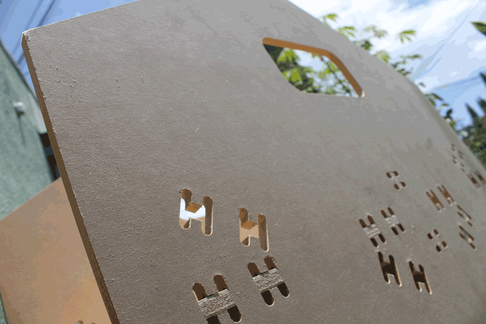
Testing Joints
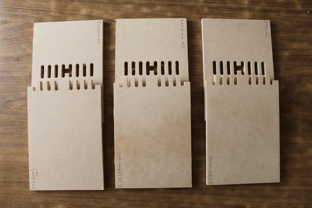
Before making something I need testing the joints, we will use differents tolerances to see how this affects the stability and the dimentions and joints that will be usefull to build without glue or nails.
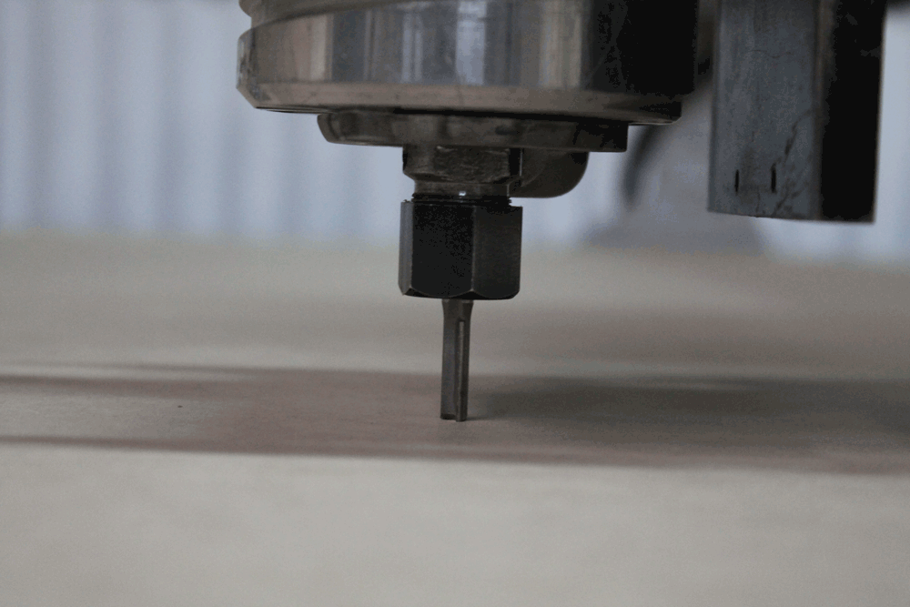
Knowing the machine
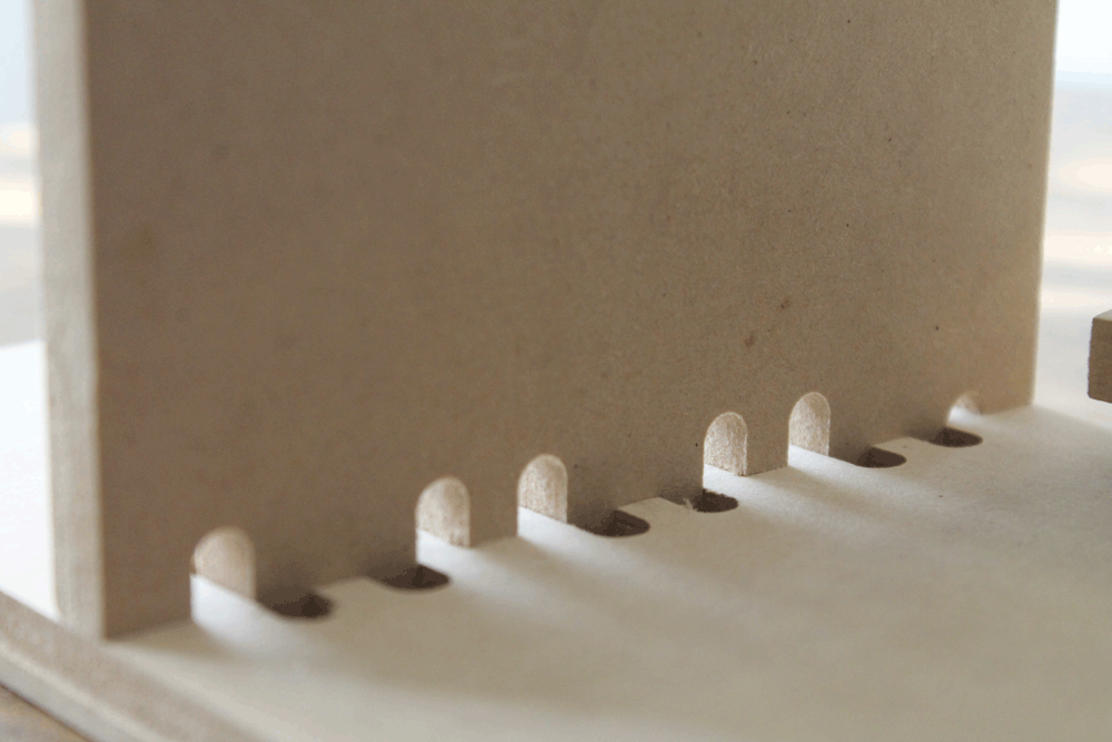
First of all this machine is known as a 2 1/2 axis machine, because it can make operations at differents depth, but it can't interpolate lines or curves on the Z axis planes, because of this the results of Z axis operations will be stepped.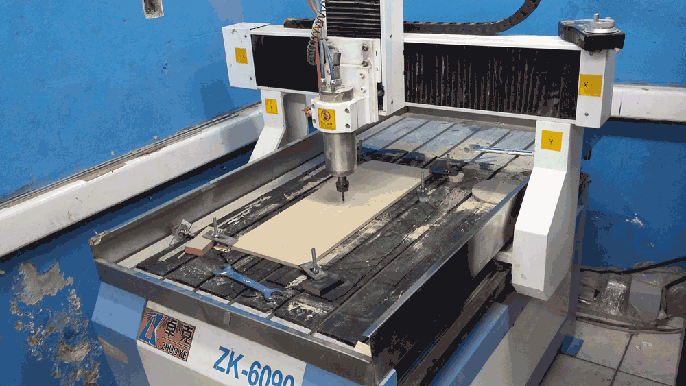
Routers use a tool named Milling Cutter, they seems like drills, but they are a little different; thanks to this milling cutters can make operations in differents directions and details.
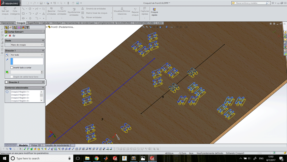
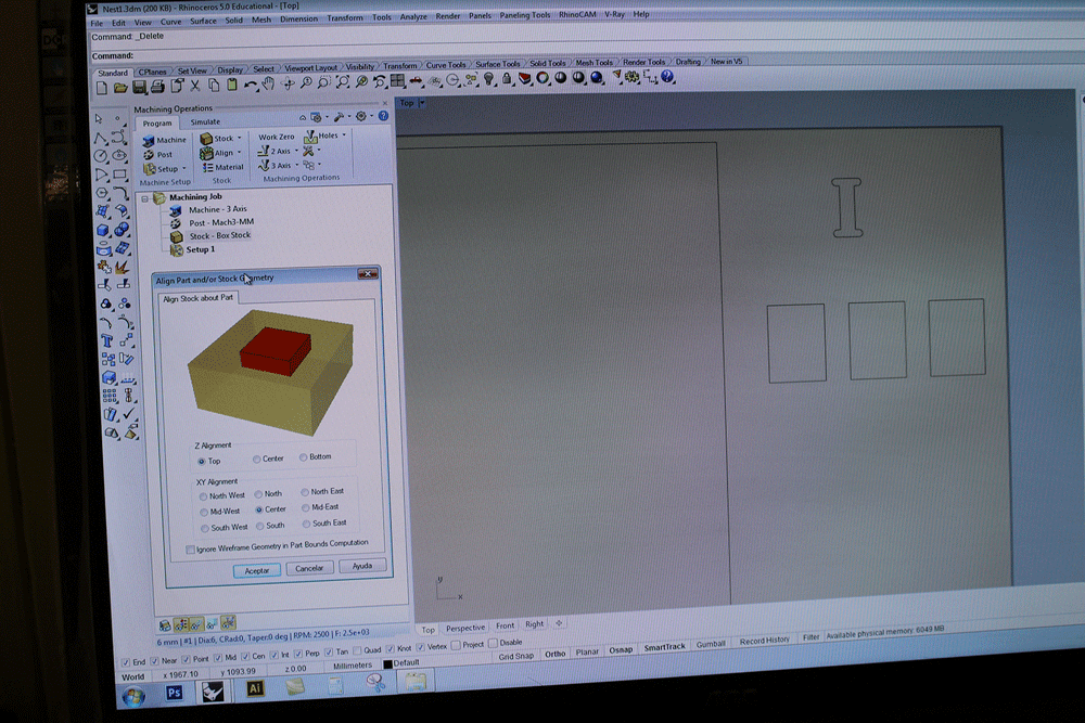
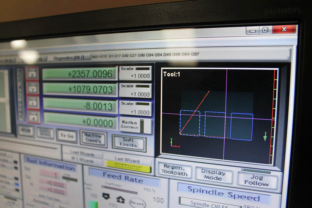
Generating G-Code
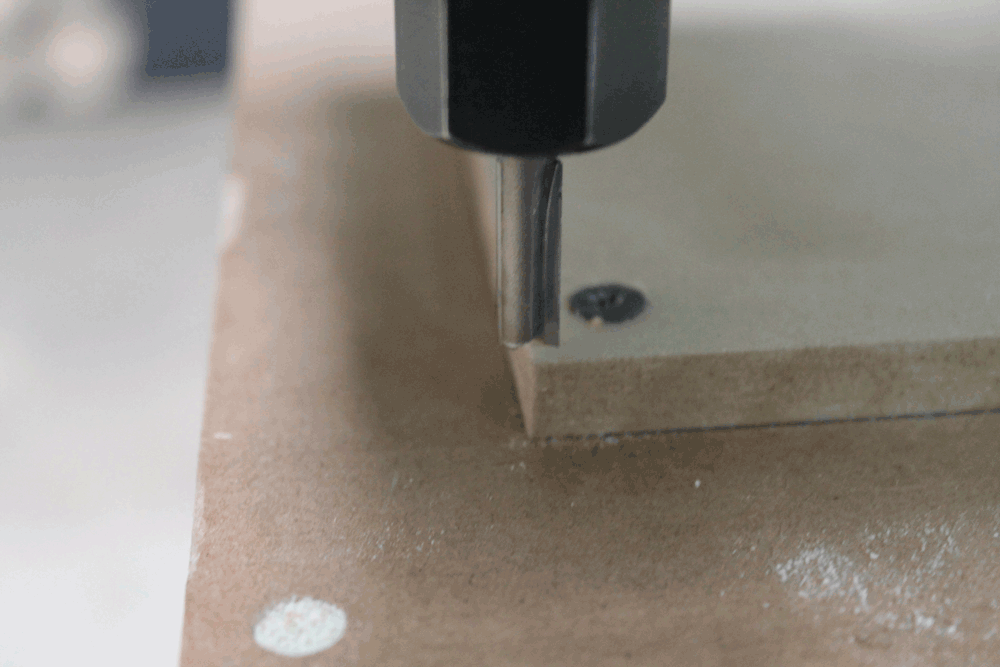
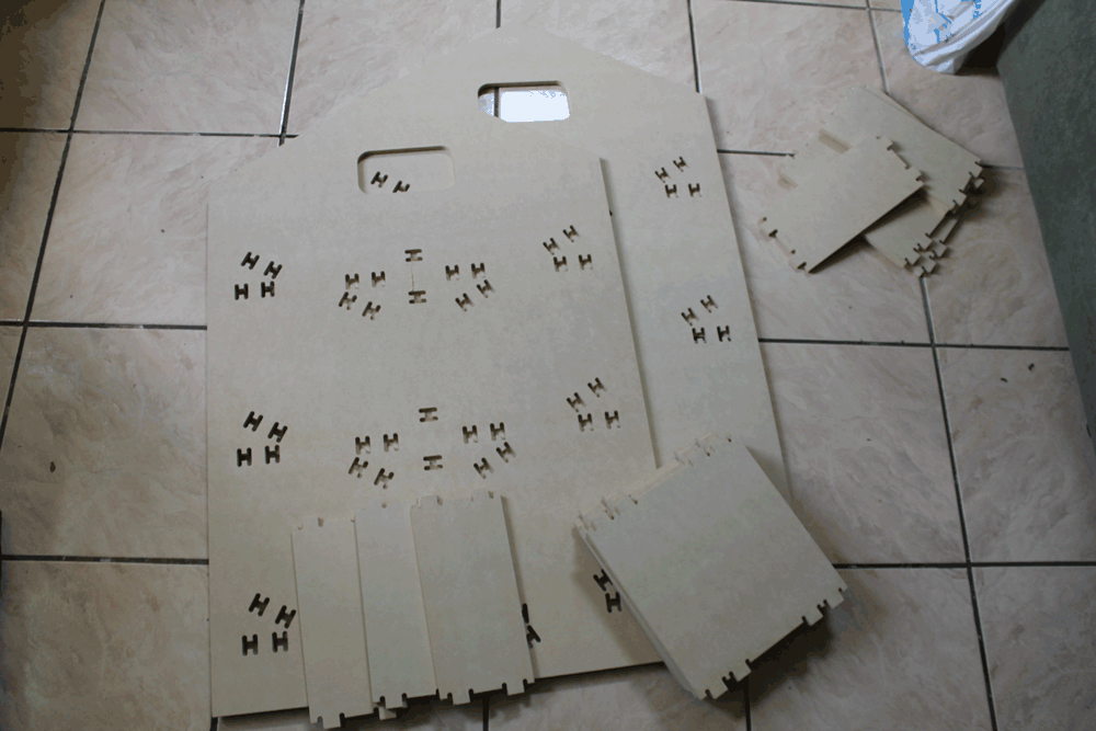
Cutting process
Try and failure
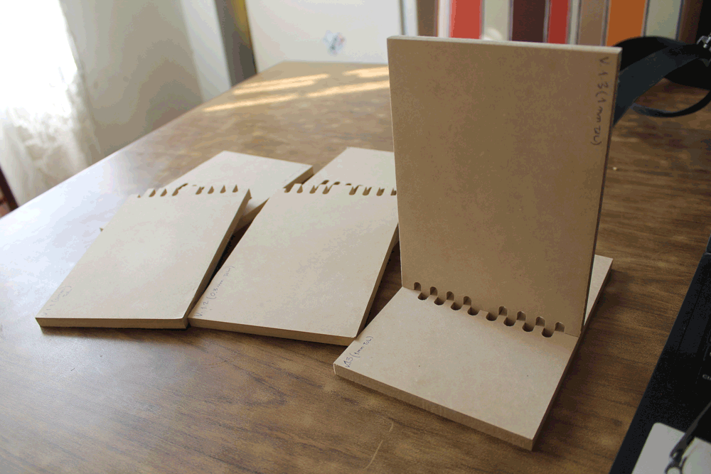
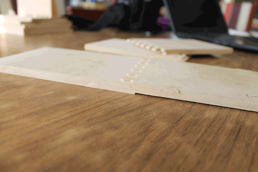
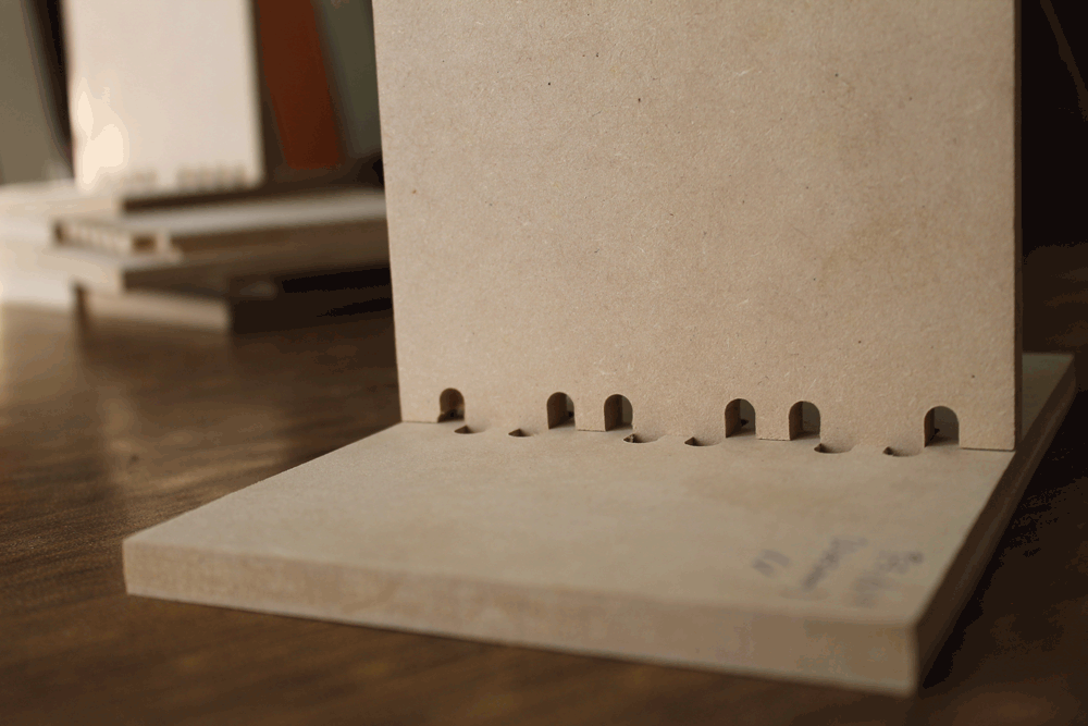
On this part we decided to test how the joint's tolerance affects on the assembly process. We tested on vertical and horizontal joints.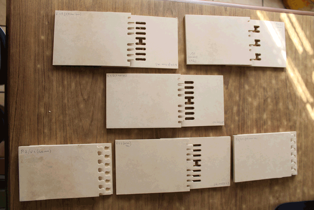
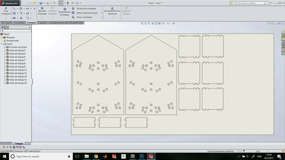
Making something big
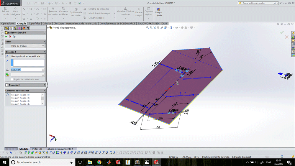
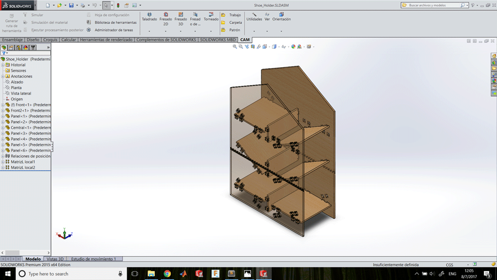
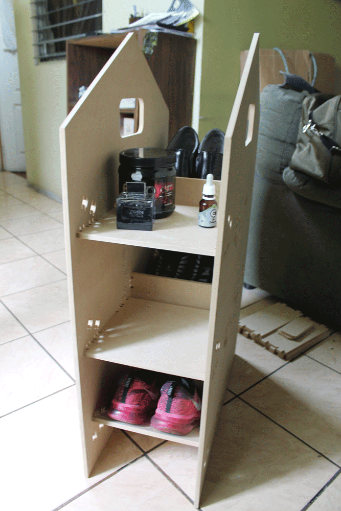
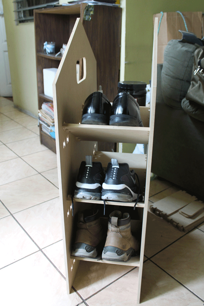
Designing a shoe holder
I designed a shoe holder that you can decide if install the shelfs tilted or horizontal, depending if you want to put your shoes or your stuffs.
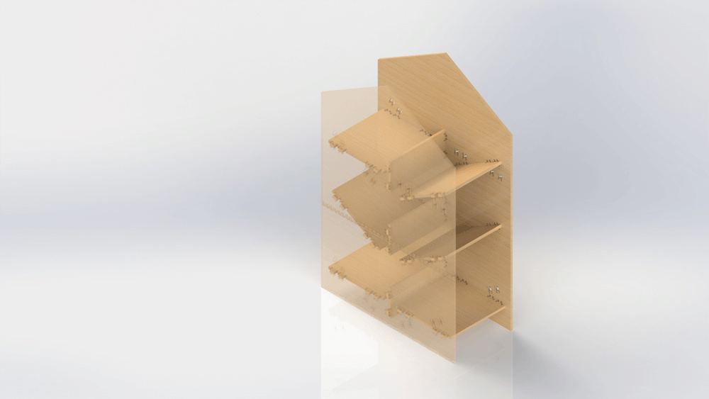
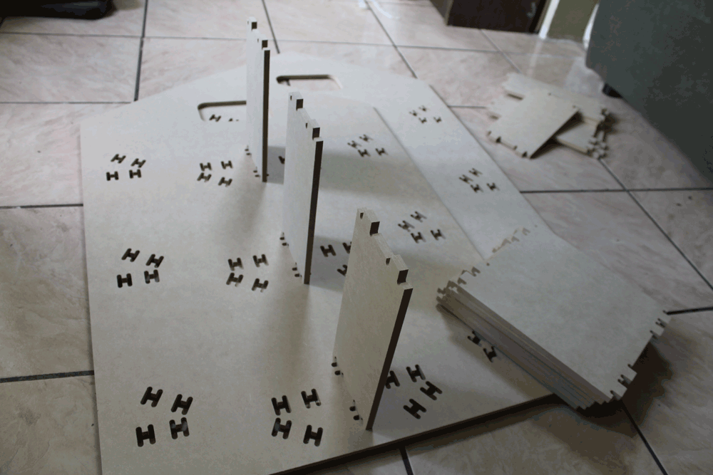
Results
After assembling everything this is the results:
Sponsors