This week we are going to explore differents CAD softwares
Machines
-
Materials
-
Evaluation of 2D and 3D softwares
2D Softwares
In the case of 2D I evaluated two types of software, those that work with pixels and those that work with vectors.
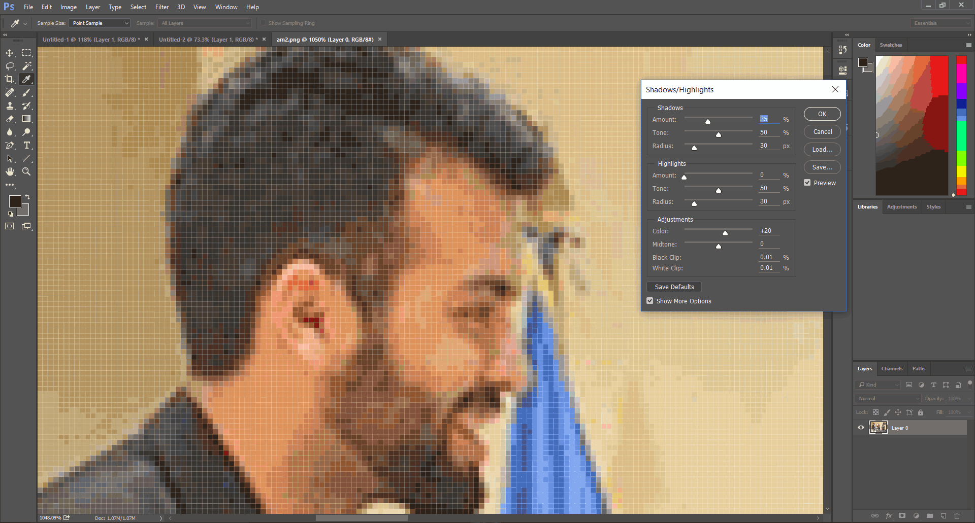
Softwares that work with pixels, such as Adobe Photoshop, are based on transformations and arithmetic operations on the information of each pixel. We need to know that the images are an information matrix, of m x n x o, where m and n are the high and wide dimensions of the image, while o is the number of layers of the image, 1 for binary images and grayscale, and 3 for RGB. Each pixel contains a number that determines the intensity of the layer to which it belongs.
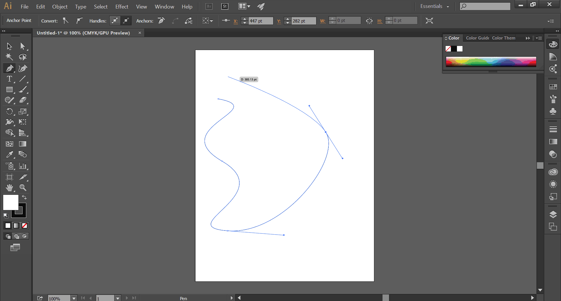
Softwares that work with vectors, as Adobe Illustrator, are based on dependent geometric elements that have properties of form and position, the greater advantage of this type of images, compared to the ones of pixels, is that its visualization is independent to the zoom, since that we can modify the size of the image without losing its quality.
3D Softwares
In the case of 3D, I evaluated three types of programs, those that operate based on operations, nurbs and sculpt modeling.
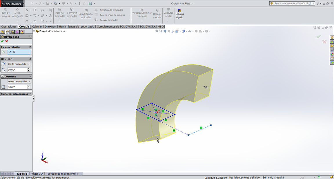
First kind of 3D software function by operation of adding (extrude or revolution of a plane surface), subtracting (cutting) and modifying the material, and are characterized by being parametric, this means that each operation can be modified regardless of the progress or its relations and interaction with other parts. You can modify in any stage of the design proccess, inclusive if you have already done the plans. I will show you later this software.
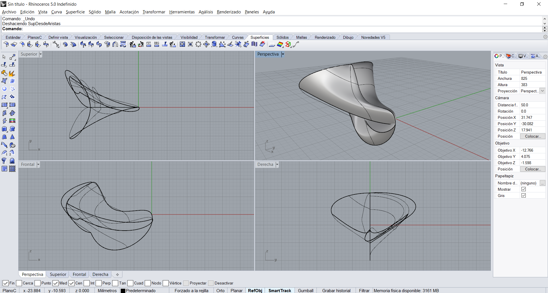
In contrast, NURBS (non-uniform rational B-spline) editors, such as Rhino, work by modeling surfaces defined by mathematical functions, which can be modified by control points. The advantage of this type of software is that they allow more free modeling. The way to make curves and vectors is the same that we used on Illustrator, only that in this case we can and need to close 3D curves to define a surface.
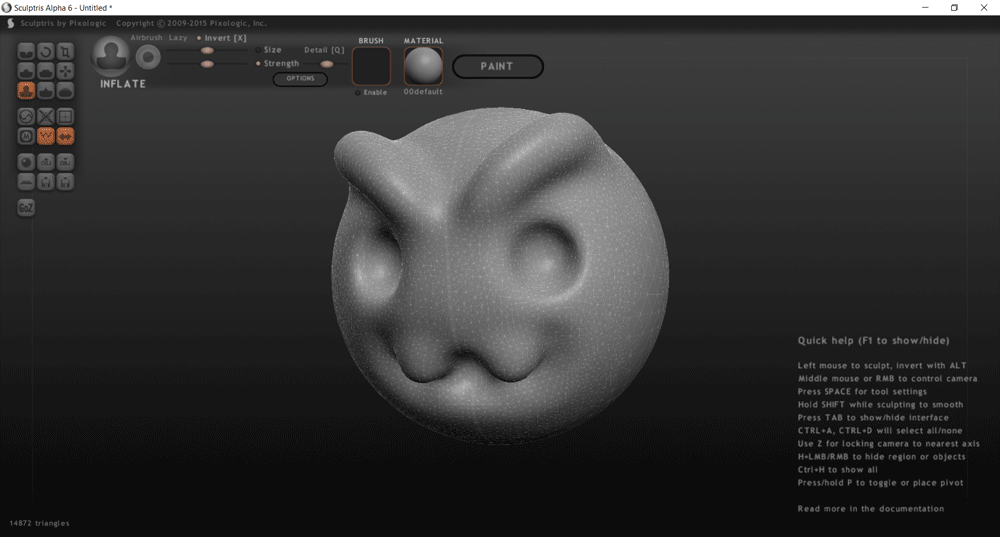
And finally sculpt modeling, like Sculptris, is based on the deformation of a base geometry body, like an sphere or a cube, by pressure and stretching operations. This is a much freer option in terms of forms, but much less accurate; this type of software serves to model characters and environments, but without being able to define exact measurements, more than a visual parameter.
2D and 3D Modeling Proccess
2D Proccess
For the 2D CAD I chose Adobe Illustrator, in which I took tools like pen, the fill and stroke color boxes, the dropper, shapes and text to generate a basic sketch of the update of my project.
3D Proccess
For 3D CAD I chose Solidworks, as I mentioned before it is parametric software, so it follows a logic of making a 2D sketch, modifying it by means of dimensions, and then occupying it in a 3D operation. There are two main operations adding or cutting material, which are implemented by extrusion, revolutionized, swept or matrices, in general terms; Then we have modification operations like chamfers, bevels, reinforcements, etc ... It is necessary to take into account that Solidworks is a very complete program, with which we can generate plans, assemblies, animations, rendered in addition to CAD.
In my case, I only used two of these processes: CAD and assembly, to get a general idea of the 3D project.
As we can see in the following GIF the process I followed was as follows:
For the assembly process:
At this point I can do a couple of motion tests.
Multiplatform process
This process is the one that involves 2D and 3D platforms to be able to generate files for the production of our model especially in low resolutions. This was my process: