The Project development
CYMATIC MIRROR SLIDE CYMATIC MIRROR VIDEO
The project consists in making visible the frequencies that the human body emits, through the cymatica. The project is divided into phases: 1- Measure the date. 2- Process it. 3- Send it to the speaker. The speaker is placed on a platform, where a camera will be connected that will emit the image of the cymatica by means of a projector.
PROJECT DETAILS
Processes:
Laser cutting, 3D printing, CNC Routering, Electronic design (Ouput, Input), Programming.
Machines:
RedSail 1200x900 mm, , RedSail MI325A details, Mini CNC engraving machine.
Materials:
1 x 20cm acrylic plate/ 1 Speaker/ 1 case CNC MDF 18mm/ 1 APAM8403 Amplifier/ AD8232 Heart Rate Monitor/ biomedical sensor pads / 1 Fabduino/ 3D printed pieces/ 4 nuts.
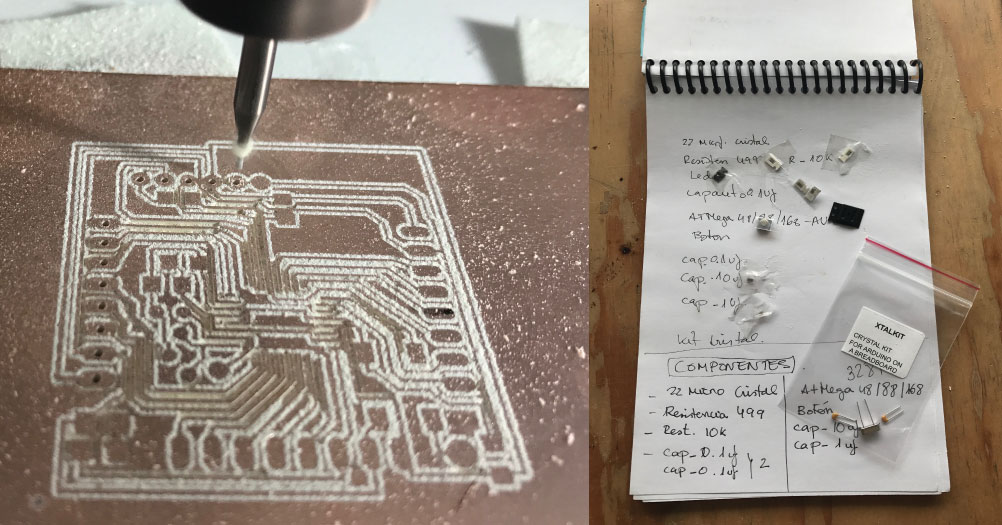
Components Fabduino:
Cristal kit 16mhz/ resistor 499 ohm/ resistor 10k/ Led/ capacitor 1uf/ 2 capacitor 0.1 uf/ capacitor 10uf/ botton/ ATmega3284.
Components Amplifier:
APAM8403 Amplifier Board / 1 mosfet/ 1 regulator/ 1 capacitor 10uf/ 1 resistor 499ohm/ 1 green led/ 1 resistor 0.01ohm/ 4 pines 2x1/ pines 11x1.
Components power regulator:
Regulator 5v/ regulator 3.3v/ capacitor 0.1uf/ 1 resistor 499ohm/ led/1 resistor 0.01ohm/ pines.
Drive files:
Download week work
Archive files:
case_top.stl / cnc_case.3dm / laser_case_inside.3dm / laser_container.ai/ cymaticmirror.ino/ power_regulator.brd/ power_regulator.sch/ power_regulator.png/ join3d_2.stl/ join3d.stl/ mot_duino.brd/
mot_duino.sch/
mot_duino.png/ output_amplifier.brd /
output_amplifier.sch /
output_amplifier.png
CONCEPT:
My goal for this project was to somehow be able to visualize the invisible things. For years I have worked with sound and I knew that I wanted to work with frequencies and forms.
So, I thought how I could visualize the sound, but actually my question was ... how could I visualize my own sound? As you would be the frequency emitted by the human body.
Clearly each individual vibrates at different frequencies .. would it be possible to see the difference between them?
Therefore, I finally decided that the way to see these forms or these frequencies could be through cymatica. With these ideas is how started the entire development of the project.

QUESTIONS?
1. what has worked? what hasn't? / 2.What questions need to be resolved? / 3.What will happen when? / 4.What have you learned?
1. WHAT I WORKED

I´m doing diferents test using diferent sensors moduls, like Magnetic Sensor Switch, Reflective Infrared Optical Sensor , AD8232 Single Lead Heart Rate Monitor, Biomedical Sensor Pad (10 pack), HMC5883L Triple Axis Compass Magnetometer Sensor Module, MLX90614 Non-Contact Sensors, to know which of them emitted a reliable data about the body and how it emitted it, to know if it could amplify it to be able to obtain the forms of cymatica in the machine.

AD8232 HEART RATE MONITOR:
Finally and after many tests the sendor that I have selected for the project has been AD8232 Heart Rate Monitor.
The first tests were with arduino one only to make the test, and to visualize the electrical impulses. I connected the biosensors in different parts of the body to see the different electrical stimuli, but the distribution that appears in the graphic is the one indicated to receive the heart beat.
Use the code that comes to make the sensor test, and everything worked correctly.


APAM8403 AMPLIFIER BOARD:
This board is a very important piece for the project, since it is essential to generate the waves in the liquid to amplify the input signal. So design a board that could fit the PAM8403 Mini 5V Audio Amplifier Board With Switch Potentiometer.
The diagram consists of input, to receive the data, amplifying it to two outputs one for right and one for left, the amplifier is powered with 9v. I designed the board, with eagle, that is the program in which I have worked all the assignments and it´s easy for me for design. Once the design is obtained, proceed to the process of routing, drilling and cutting of the board.
The components I have used for this board are: APAM8403 Mini 5V Audio Amplifier Board With Switch Potentiometer / 1 mosfet / 1 regulator / 1 capacitor 10uf / 1 resistor 499ohm / 1 green led / 1 resistor 0.01ohm / 4 pin 2x1 / pin 11x1.
The welding part is my favorite, since it is a challenge to work with such small components. When the board is finished, finish the process by soldering APAM8403 Mini 5V Audio Amplifier Board with Switch Potentiometer. This component will buy it in an electronics store for a price of 2 $. For what was satisfactory, having made an amplifier with very good results at such a low cost.


AD8232 HEART RATE MONITOR + APAM8403 AMPLIFIER BOARD:
Finally I connected the amplifier to an input AD8232 Single Lead Heart Rate Monitor, and the output to a speaker to be able to obtain the electrical impulses of the amplified body that could be audible. First objective covered for the project, make the invisible visible or audible.


POWER REGULATOR:
The power regulator was a need I had not planned. But having to unite all the modules in the same machine, it was complicated to have to feed all the parts, with different powers. So I designed with the help of Cesar Cruz, our teacher of electronics, this system where you can connect the different modules, input and output according to the needs that my project needed.
As you can see in the diagram, there are an input and output of 9v, two outputs of 3v, and two other outputs of 5v. This board is powered by a 9v battery, which distributes the pontencia in to the different outputs.


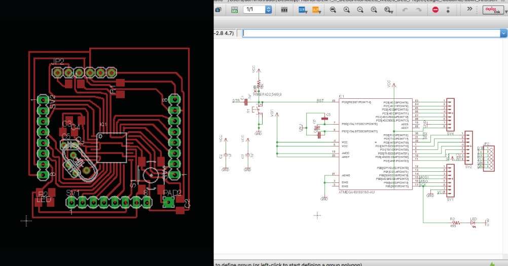
FABDUINO MODIFIED:
This board was one of the challenges of fab academy, I had to design and produce several models, to finally get one that will work for the project and for the weekly assignments. In the Fab Lab, we had to use to design the arduino, a crystal of 16mhz with 2 consensadores and not the one of 20mhz like the original, since it was the one that we could obtain and had compatibility with the code. (The process of this board can be extended in Assignment 4)

FABDUINO MODIFIED + AD8232 HEART RATE MONITOR + APAM8403 AMPLIFIER BOARD + POWER REGULATOR:
It is time to combine the components to be able to have the final prototype. The wiring has been somewhat complex to organize, you can see the outline in the design I made in the next photo. The data is output by the AD8232 heart Rate, and output to the fabduino to pin A0 where it will be processed by the indicated programming so that it can emit musical tones when receiving sound stimuli. The ouput comes out of pin 8 from the arduino to the amplifier that transmits it to the speaker. All this is powered by a 9v battery, which through the relay distributes the powers to the different components.

PROGRAMMING
Use as a basis the example of Sparfunk indicated for the sensor, the problem is that the electrical impulses are very changing and could not define a continuous form in the liquid. So I needed to process the data using a Fabduino and be able to delay the input time. The digital network is programmed so that the sensor does not receive information stops with "no tone" and when it receives data "tone" emitting a continuous frequency, to which I can modifical the delay, in this case it is in 2 seconds of delay. Hear_rate.ino


CYMATIC MACHINE
TESTING PATTERNS
First experiment was test the display with pure frequencies emitted by a generator of frequencies from my mobile. The results were incredible, beautiful patterns appear in the water, while I was changing frequencies through a frequency generator. The expectations for visual results were beginning to grow.


CNC CASE
Use the CNC router tool, since it was clear that you wanted a wooden box with a compact appearance and easy functionality. To do this design the piece with 3d modeling in rinoceros, to get an idea of the final product and its different parts. The process was divided into two parts, one part of cut, by parts exported to 2d, with easy execution of cut, and another part that was the top cover, in which the piece had to be exported in 3d, adjudicandoles to files Necessary data for the process as can be seen in assignment 12. This time I did not commit as many blacksmiths as the first few times I used the cnc router, and I took into account the size of the drill 12mm, and the thickness of the material in its design 18mm of wood in this case. In order to change the batteries and organize the sensors, design an opening system, using a rotating shaft. This axis was the support that served as tripod for the project The final results were as expected.


3D JOINS
The part of 3d printing, was a subject more accessory for the project, but for me it was important to have a support where to place my camera, or the mobile, where to register the patterns of the different people in order to be able to compare them . So use the Rinoceros to do 3d modeling, then export it in .STL. The program I used for printing was Cura, and the 3d printer a printerbot, with a black PLA filament.


LASER CUT CASE
Use the laser cutter to develop a system of internal organization of the modules. Design the part in rhinoceros with the measurements of the piece of the wooden cade. Finally I generated a sub-box with different layers, in which I could organize the components, and the cables, without looking as messy as in the initial delivery. Use several materials, 5 layers of 3mm mdf, and a top layer with nobles of transparent 3mm acrylic modules. Also use this technique to put personal branding details, and create the accessories for the use of the machine, such as the water jar.


FINAL PRESENTATION:


This work is licensed under a Creative Commons Attribution-NonCommercial 4.0 International License.
FINAL VIDEO PRESENTATION:
Proyecto final_Fabacademy from Montserrat on Vimeo.
CHANDLI PATTERNS PROTOTYPE


First Video_Draft from Montserrat on Vimeo.
2.What questions need to be resolved?
My intention was to continue with a second stage of visualization but digital, which I could not get to work because of time. The idea is to continue experimenting with processing and digital display programs. This part is one of the ways that I want to continue developing to be able to get the patterns of cymatica, in code and be able to work with digital manufacturing tools.
3.What will happen when?
It seems that time is my battle enemy, every week. The interior of the project and its function was well advanced in the last months. So in these last weeks, the part that I have to develop is the aesthetic part of the project. Everything related to foma and functionality in the product, and its applications. The project aims to become one of a series of works with sound art and science and therefore this last part of the process should position the project as an object work, and less like a prototype. An object with possibilities to expose and that I have good results.
4.What have you learned?
i
What I have learned to be wrong once behind another, I have learned the importance of prototyping when making a final project and how to take into account that all the details count for the digital manufacture. Right now I consider myself able to use the tools of a fab lab with complete independence, and technical knowledge. That has been the biggest contribution of this process, being able to do almost anything.