MTM 2: ‘MAGGY’ CNC Drawing Machine
This we are going to build a mechanism to as a first step to make a machine, we are going to use James Coleman and Nadya Peek project as a tutorial to construct our 2 axis CNC drawing machine.

IDEATION
The biggest problem in El Salvador and some countries of Central America is the social violence that we live. This issues motivated our team to development one project for kids for that reason we selected one project of ‘Machines to make machines’- an interesting program of CBA that its machines with low budget and trying to adapt our assignment with our reality and build capabilities to reply with Fablab SV this machine in projects for kids with the CIPITLAB program.
We focus and replicate one of the 28 machines that they are development and share in detail of all the process and files to reply. Our selection it’s this easy machine named: [m]MTM: modular machines that make developed for James Coleman and Nadya Peek. This project has all the information like a tutorial to construct the two boxes we are using as X and Y axis.
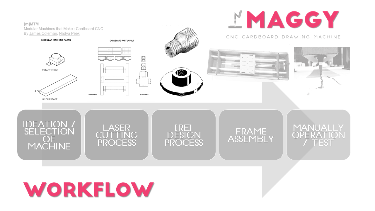
The challenge that we are focus is ‘How can we adapt this project to kids’ and can make this machine in 2 days to learn more about technology and have empathy with days to catch their attention and interest with this project of one CNC Cardboard drawing machine that we named MAGGY and we created this Logo for the identity of this machine focus in kids, you can see the proposal in the next image and the Workflow diagram after it.

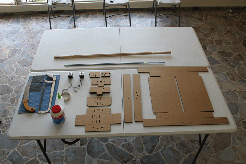
LASER CUTTING PROCESS
Once we downloaded James and Nadya’s file, we opened it in Adobe Illustrator CC to sent it to a Trotec Speedy 300 laser CO2, we cut in 3mm cardboard sheets. We didn’t change anything in the file and sent to cut as the original file was. At the end of the process, we classified and separate all the cardboard pieces and prepared all the necessary materials to use to make the assembly process easily.
We downloaded the original cutting files here.
[Re]DESIGN PROCESS
Nut coupling
In the moment we assembled the wooden sticks and the threaded rod, we realized that we had to make some changes in the inside of the two little cardboard boxes in order to fix a threaded rod guide, otherwise the hole in the cardboard box will become bigger and bigger as the rod passes into it. To prevent the hole wear, we design an acrylic piece with an aluminium nut in the center to lead the bar movement into the box, using as example the coupling that is used on the tutorial. We also made a modification in one of the inside pieces of the box which moves through the rod, because the space to fix the acrylic piece was too thin, so we made it wider.
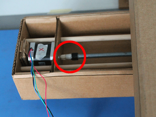
Motor coupling
To make the union between the motor and the rod, we use a PLA 3D printing coupling, we fix the rod and the coupling piece with super strength glue, and to the motor pin by pressure.We had to modify a file that we found on thingiverse, because the hole to put the motor pin was to small. First we tried printing the coupling with PLA and drilling the hole, but we realized that PLA sticks on the drill when it gets hot by the friction (so we messed up a drill). Then we tried a better solution, we modified the STL file to print it later.
To modify the STL file we used Autodesk Fusion 360:
You can download it here
End effector support
As we have already decided that the machine will draw with a marker we have to make the piece that will support the marker. We used SolidWorks, and the only three parameters that we need are the marker diameter the bolt diameter and height. We have some inconvenients to printing it, because we didn’t consider the tolerances of the 3D printer and when we tried to put the bolts and the marker they didn’t fit, so we had to increase a little this dimensions, like decimal of millimeter.
You can download it here
Frame support
We also design two cardboard legs to make a support frame and could separate the axis to the table. For this we had to take in consideration the distance from the axis to the table depending of the position of the marker in the end effector. Once we assembly the frame, we realized that it needed some supports to make it more resistant and we design stiffeners for that.
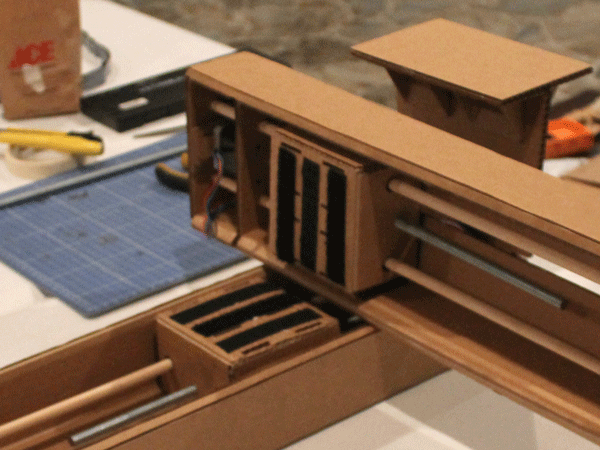
FRAME ASSEMBLY
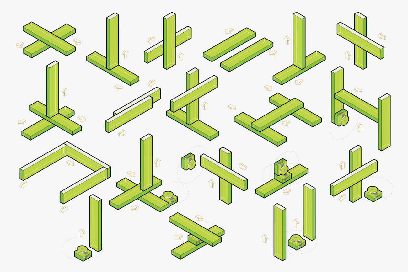
We followed step by step the tutorial and we finally had the two large boxes assembled, at this moment we used the pieces we redesign.
The challenge was how to join the two boxes to make the X and Y axis, to do that we use the support frame to have the two axis at the right distance to the table to put the marker in its place.
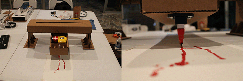
MANUALLY OPERATION
Finally we operated the machine to make a demonstration of what it does.
ASS-09 [Assembly] from Fablab Sv on Vimeo.
Machine Design
CONNECT THE STEP MOTORS
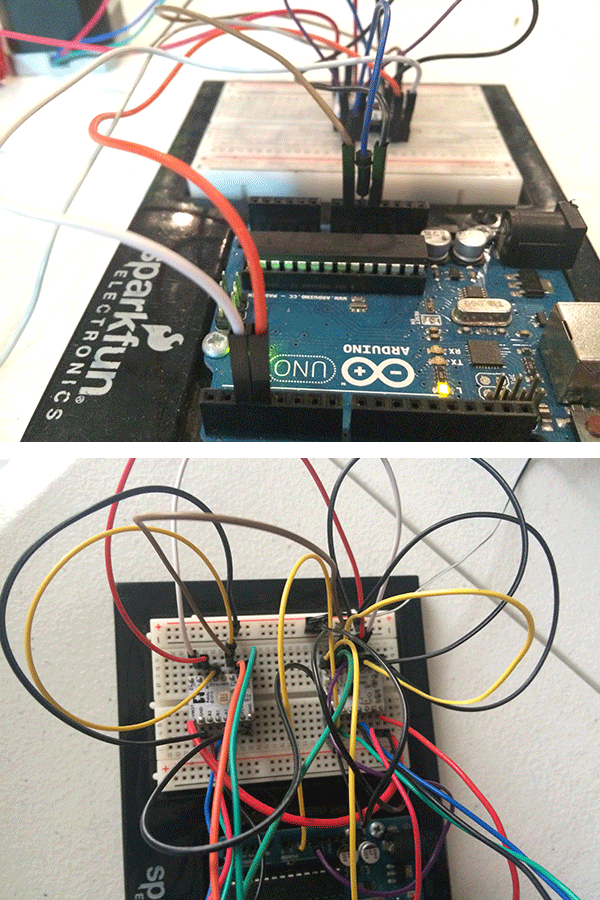
For this assignment we made the two step motors work separately first out and then into their respective cardboard boxes we will use as X and Y axis. To do that, we use an Arduino UNO board and a breadboard to be able to connect all the necessary cables using one Pololu DRV8834 driver carrier for each motor. We programed the movements using Arduino IDE.
Step motor test from Fablab SV on Vimeo.
SOLVE ISSUES
The first and most important issue was not to have the necessary materials to construct the boxes. First of all we weren’t able to find plastic or pvc bushings and aluminium pipes in the local hardware store, we had to substitute the pipes for wooden round sticks causing non accurate movements in both axis.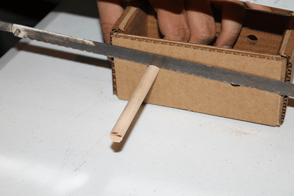
We didn’t have the Gestalt Nodes and FabNet boards either, so we had to solve the issue using an Arduino UNO board and two Pololu drivers as H Bridge to be able to move both motors at the same time.
Second issue was fasten the two axis inside boxes, we try several methods and the one worked the best was join them with Velcro tape, but we still have problems because each time we had to split them, the Y axis box is falling apart of its top cap.
Third issue we had to solve was the X axis balance, because the motor itself is 68 oz and the X axis is upside down and it doesn’t have anything supporting it, and when the axis inside box isn’t in the middle, the entire cardboard box tends to unbalance because the motors weight, causing the marker lost contact with the sheet of paper in the other side and the drawing wasn’t as accurate as we wanted, and most of the time it didn’t draw anything. To solve this issue we decide to add a spherical caster behind the motor making the necessary support and let the axis move in both directions.
Fourth issue was the motor coupling, besides we printed them in PLA, it was difficult to keep them attached to the motors pin, and sometimes at the middle of the procedure they split apart ruining everything. To solve the issue we had to paste them with super strong glue and some masking tape.
UNDERSTAND C++ CODE AND ARDUINO IDE
As we said before, we use an Arduino Uno and Pololu Driver to move a stepper motor. Before begin programming there are three things that we need to understand:Knowing this, to make the program practically we need to tell Arduino: “We need you to give 1000 steps on this direction, and for every step you have to put on 5V the step pin, wait, put on 0V, wait and repeat”
On C++, it would be this:
for (int p=0; p<1000; p++) {
digitalWrite(pinStep, HIGH);
delayMicroseconds(time);
digitalWrite(pinStep, LOW);
delayMicroseconds(timel);
}
This code lines will make that one motor give 1,000 steps. But we design our machine to move on 2 axis, so if we want to move both motors at the same time we have to tell the same to each motor, like this.
for (int p=0; p<1000; p++) {
digitalWrite(pinStepX, HIGH);
digitalWrite(pinStepY, HIGH);
delayMicroseconds(time);
digitalWrite(pinStepX, LOW);
digitalWrite(pinStepY, LOW);
delayMicroseconds(timel);
}
This would do that both motors turn at the same time with the same speed, the direction is independent for each one.
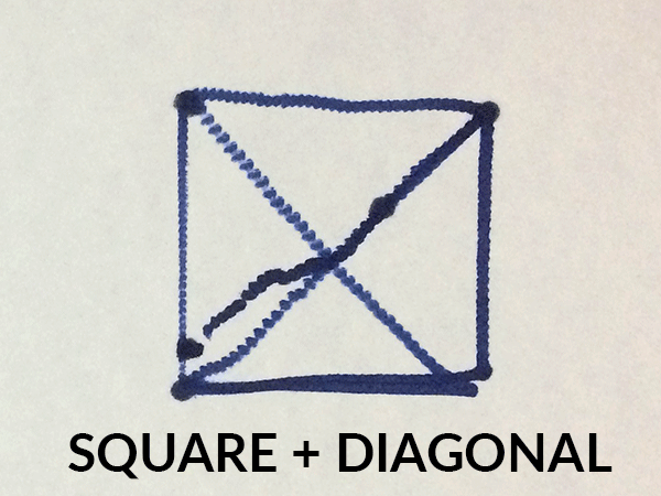
If we want a complete a program we need to set the IOs and the directions of movement, this code was our first sketch to test our machine and it will make a box with a diagonal in a very long method.
//Variables and Pin Declaration
int pinStepx = 11;
int pinDirx = 12;
int pinDiry = 10;
int pinStepy = 9;
int pinAdelante = 2;
int pinAtras = 3;
const int ledPin = LED_BUILTIN;
void setup() {
//Set IO
pinMode(pinStepx, OUTPUT);
pinMode(pinDirx, OUTPUT);
pinMode(pinStepy, OUTPUT);
pinMode(pinDiry, OUTPUT);
pinMode(pinAdelante, INPUT_PULLUP);
pinMode(pinAtras, INPUT_PULLUP);
pinMode(ledPin, OUTPUT);
//Initializing
digitalWrite(pinStepx, LOW);
digitalWrite(pinDirx, LOW); //Low get closer to motor, High get farther
digitalWrite(pinStepy, LOW);
digitalWrite(pinDiry, HIGH); //Low get farther from the motor, High get closer
digitalWrite(ledPin,LOW);
delayMicroseconds(500);
//Setting Delay
int vel = 500;
for(int p=0;p<10000;p++){ //Right
digitalWrite(pinStepy, HIGH);
delayMicroseconds(vel);
digitalWrite(pinStepy, LOW);
delayMicroseconds(vel);
}
for(int p=0;p<10000;p++){ //Down
digitalWrite(pinStepx, HIGH);
delayMicroseconds(vel);
digitalWrite(pinStepx, LOW)
; delayMicroseconds(vel);
}
digitalWrite(pinDirx, HIGH);
digitalWrite(pinDiry, LOW);
for(int p=0;p<10000;p++){ //Left
digitalWrite(pinStepy, HIGH);
delayMicroseconds(vel);
digitalWrite(pinStepy, LOW);
delayMicroseconds(vel);
}
for(int p=0;p<10000;p++){ //Arriba
digitalWrite(pinStepx, HIGH);
delayMicroseconds(vel);
digitalWrite(pinStepx, LOW);
delayMicroseconds(vel);
}
digitalWrite(pinDirx, LOW); //Down-Left
digitalWrite(pinDiry, HIGH);
for(int p=0;p<10000;p++){
digitalWrite(pinStepx, HIGH);
digitalWrite(pinStepy, HIGH);
delayMicroseconds(vel);
digitalWrite(pinStepx, LOW);
digitalWrite(pinStepy, LOW);
delayMicroseconds(vel);
}
digitalWrite(pinDirx, HIGH);
for(int p=0;p<10000;p++){ //Up
digitalWrite(pinStepx, HIGH);
delayMicroseconds(vel);
digitalWrite(pinStepx, LOW);
delayMicroseconds(vel);
}
digitalWrite(pinDirx, LOW); //Down-Right
digitalWrite(pinDiry, LOW);
for(int p=0;p<10000;p++){
digitalWrite(pinStepx, HIGH);
digitalWrite(pinStepy, HIGH);
delayMicroseconds(vel);
digitalWrite(pinStepx, LOW);
digitalWrite(pinStepy, LOW);
delayMicroseconds(vel);
}
digitalWrite(ledPin, HIGH); //Turn on LED when finish
}
A very large code, and it will be larger if we want the machine to execute more movementsl, so we realized that we can sintetize it by making a function with the code that is repetitive, and this is the "for cycle".
MEASURE DISTANCE VS TIME STEP MOTORS MOVEMENTS
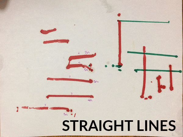
But first we need to measure some parameters, like the relation of the rotation and the straight line distance, and the relation of the delay with the speed.Once we had the X and Y axis assembled and the motors connected, we made the program to draw horizontal and vertical lines using first milliseconds and measuring how many centimeters the motors ran in that specific time. Using that information, we were able to define a formula to make the motors run changing the distance instead of changing the time.
Thanks to this calculation we could define that the amount of steps it will be equal to the stright line distance we want to draw on milimeters multiplied by 250
steps = distance * 250
And the delay will be a factor of 15,000,000/(1200*6.25) divided by the linear speed on milimeters per seconds
delay = 15000000/(1200*6.25*linearSpeed)
int pinStepx = 11;
int pinDirx = 12;
int pinDiry = 10;
int pinStepy = 9;
const int ledPin = LED_BUILTIN;
void setup() {
//Set IO
pinMode(pinStepx, OUTPUT);
pinMode(pinDirx, OUTPUT);
pinMode(pinStepy, OUTPUT);
pinMode(pinDiry, OUTPUT);
pinMode(ledPin, OUTPUT);
//Initialize
digitalWrite(pinStepx, LOW);
digitalWrite(pinDirx, LOW); //Low hacia el motor, High fuera del motor
digitalWrite(pinStepy, LOW);
digitalWrite(pinDiry, HIGH); //Low fuera del motor, High hacia el motor
digitalWrite(ledPin,LOW);
delayMicroseconds(500);
//Instructions
line(40, String('l'), 4.5);
line(20, String('d'), 4.5);
line(40, String('r'), 4.5);
line(20, String('d'), 4.5);
line(40, String('l'), 4.5);
diag(40, 40, String("ul"), 4.5);
diag(40, 40, String("dl"), 4.5);
}
void loop(){
}
//Functions
void line(int dist, String dir, int velmot){
//10,000 steps are 25 turns and 4cm
int vel = 15000000/(1200*6.25*velmot);
int steps = dist*250;
int pin;
if (dir == "u"){
digitalWrite(pinDirx, HIGH); //Up
pin = pinStepx;
} else if (dir == "d"){
digitalWrite(pinDirx, LOW); //Down
pin = pinStepx;
} else if (dir == "r"){
digitalWrite(pinDiry, HIGH); //Right
pin = pinStepy;
} else if (dir == "l"){
digitalWrite(pinDiry, LOW); //Left
pin = pinStepy;
}
for(int p=0;p
delayMicroseconds(vel);
digitalWrite(pin, LOW);
delayMicroseconds(vel); }
digitalWrite(ledPin, HIGH);
delay(500);
digitalWrite(ledPin, LOW);
}
void diag(int distx, int disty, String dir, int velmot){
//10,000 steps son 25 vueltas son 4cm
//int teta = atan(disty/distx);
//int velmotx = cos(teta)*velmot;
int velx = 15000000/(1200*6.25*velmot);
//int velmoty = cos(teta)*velmot;
//int vely = 150000000/(1200*6.25*velmoty);
int stepsx = distx*250;
int stepsy = disty*250;
int pin;
if (dir == "ur"){
digitalWrite(pinDirx, HIGH); //Up
digitalWrite(pinDiry, HIGH); //Right
} else if (dir == "ul"){
digitalWrite(pinDirx, HIGH); //Up
digitalWrite(pinDiry, LOW); //Left
} else if (dir == "dr"){
digitalWrite(pinDirx, LOW); //Down
digitalWrite(pinDiry, HIGH); //Right
} else if (dir == "dl"){
digitalWrite(pinDirx, LOW); //Down
digitalWrite(pinDiry, LOW); //Left
}
for(int p=0;p
digitalWrite(pinStepy, HIGH);
delayMicroseconds(velx);
digitalWrite(pinStepx, LOW);
digitalWrite(pinStepy, LOW);
delayMicroseconds(velx);
}
digitalWrite(ledPin, HIGH);
delay(500);
digitalWrite(ledPin, LOW);
}
This code works as a "Baby G-Code" because we only need to specify, for example, in the command line(distance, direction, speed) and in the command diag(distance X, distance Y, direction, speed). It still has some delimitation, it can't draw diagonals lines with an angle different from 45°, and can't draw curves.
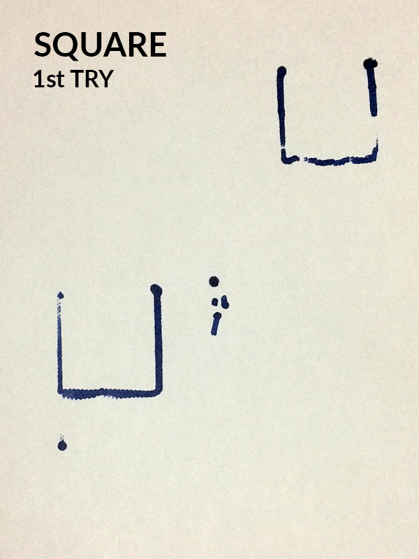
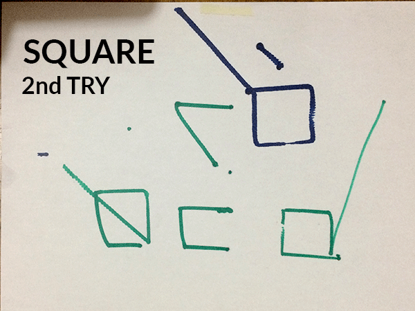
RESULTS
Here is the sequence of the test that we made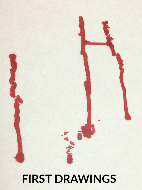
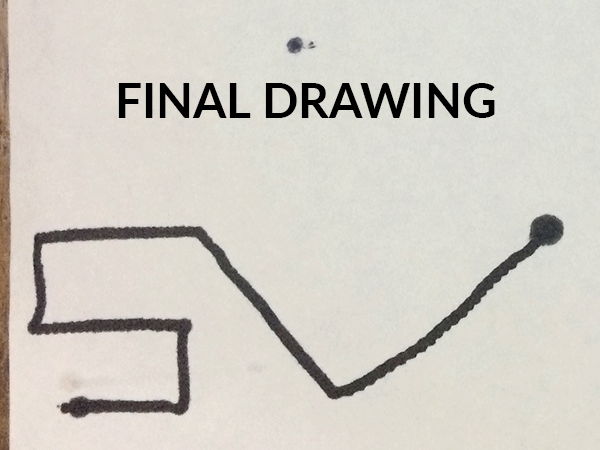
Here is a video of what does the last program that we make!!!
Week 11 - Machine Design from Ivan Lopez on Vimeo.
Team members

Damaris Cotto

Carlos Valladares

Ivan López