OBJECTIVES
Make an in-circuit programmer by milling the PCB
Make an in-circuit programmer by milling the PCB
For this assignment we have to make a FABISP, this means, that this card can be used to program embedded devices.
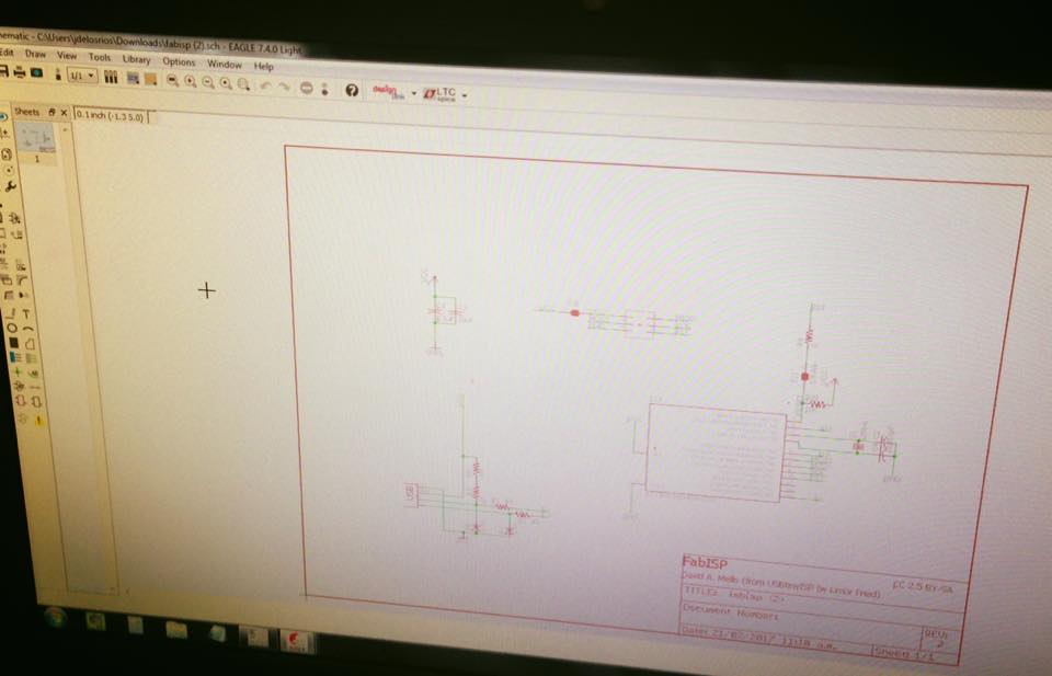
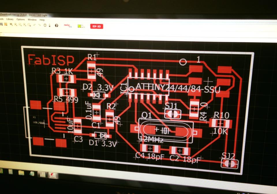
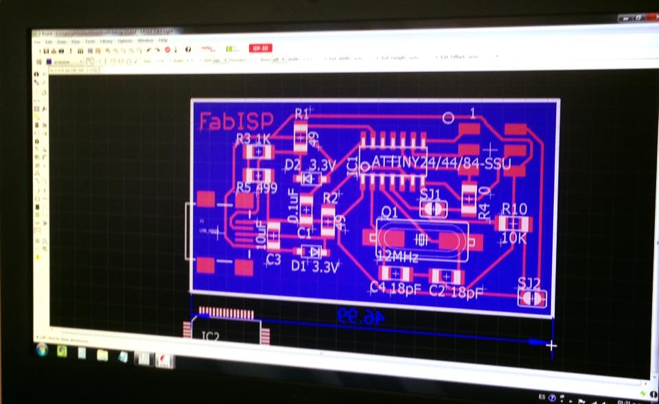
From the fab web I downloaded one of the available Fab ISP designs, in my case, the one from David, which is:
SCHEMATIC
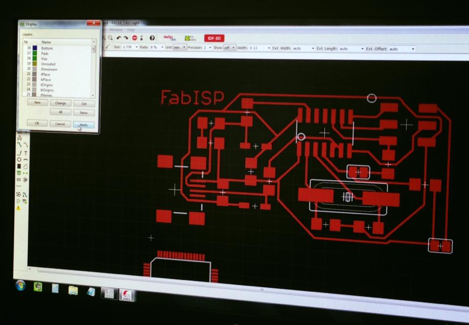
BRD
For this model I needed the following components :
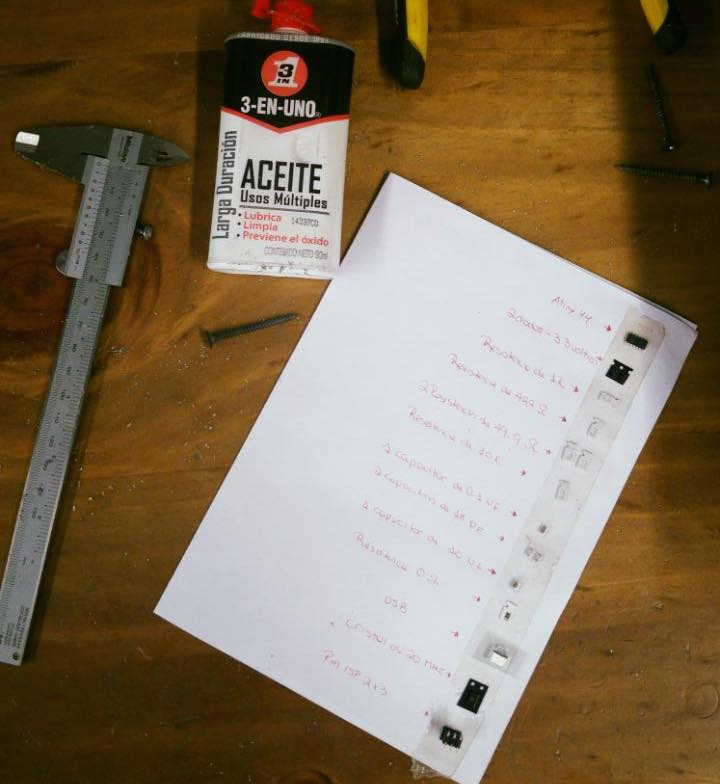
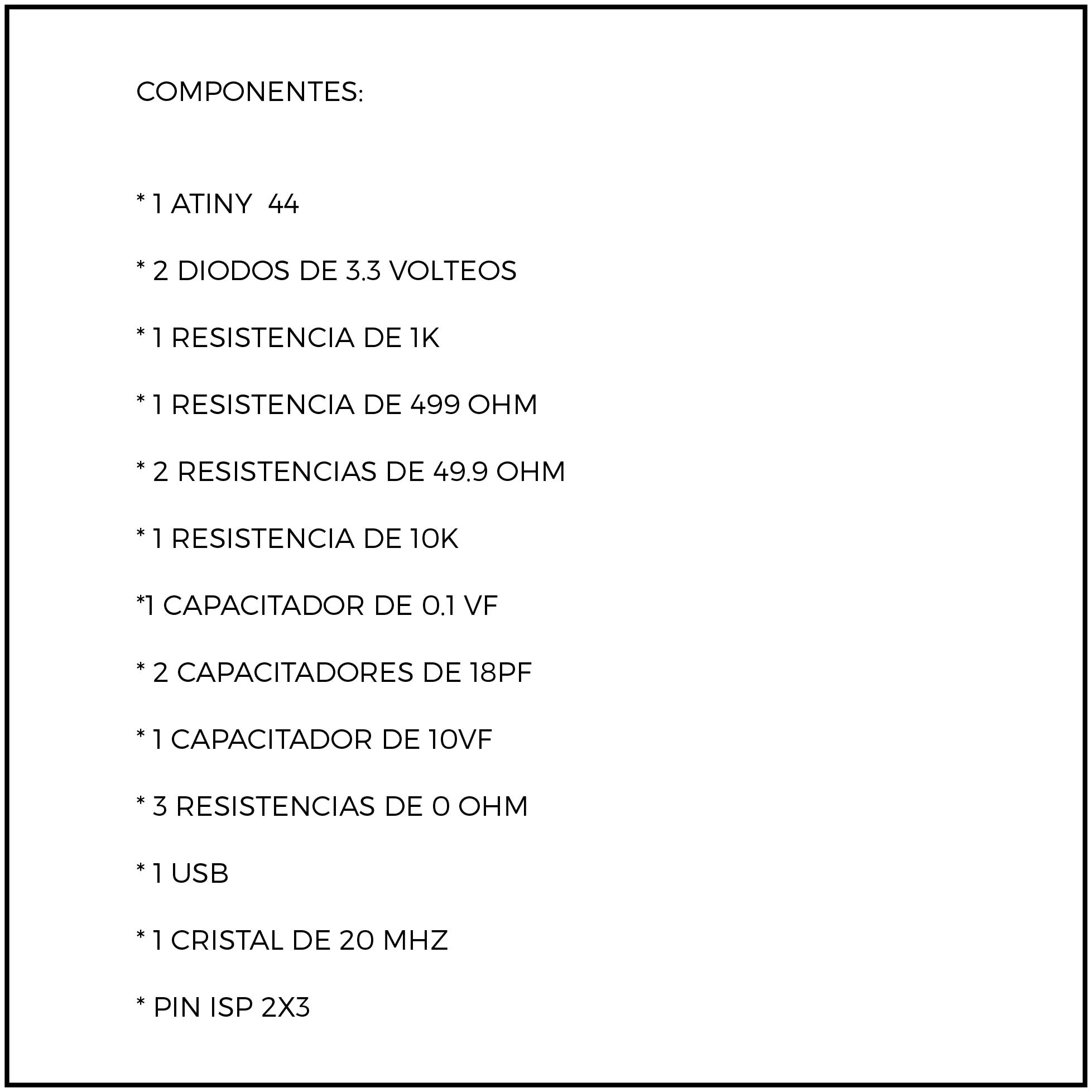
COMPONENTS
I downloaded the David card and opened it EAGLE, there, i had to check the card size to mill, which is 46.9mm x 26.04 mm To mill it only needed the top layer so, the other ones must be unselected.
To mill the card, the milling machines needs a folder with a “.g” extension so it has to go from Eagle “.brd” to Cam Processor so it can be changed to “.g”
After the work on Eagle, one must go to the Flat Cam 8.5 software, which communicates to the Modella Machine and allows you to set the work that needs to be done, like the milling, the border, the path and the tools.
-There I had to select the gerb274x.com file because its the one that goes with the top layer, and save it with the .comp extension
-save the file on the desktop
- click process job
- Test en Flat Cam 8.5
- Open Gerber
- File TEST1.cmp
- Check if it is in mm
- Make a border to the card
- Work on the file with the border so it can be cut
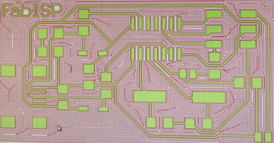
- Then I had to define how much of the card, it´s going to be milled.
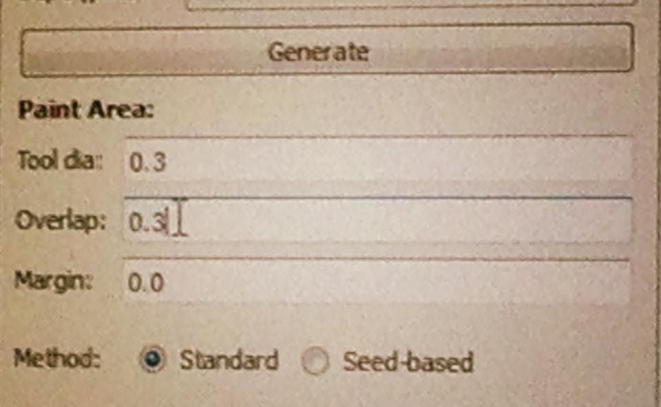
Click on Generate.
In week six there is a detail explanaition of how the Flat Cam is used and how to export the G code.
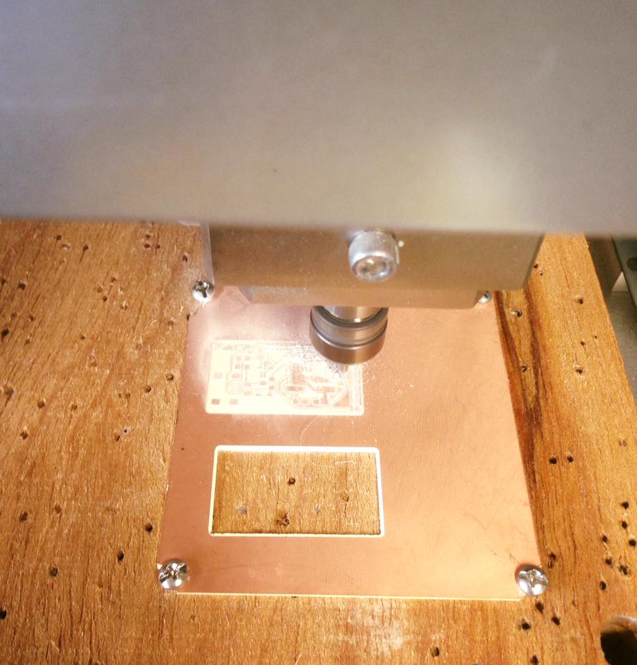
This machine would be used to mill the copper traces on the board, so its only conductive it´s needed.
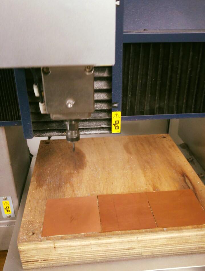
The process was like this:
- Fix the material to the Wood base of the machine so it doesn´t move during the work.
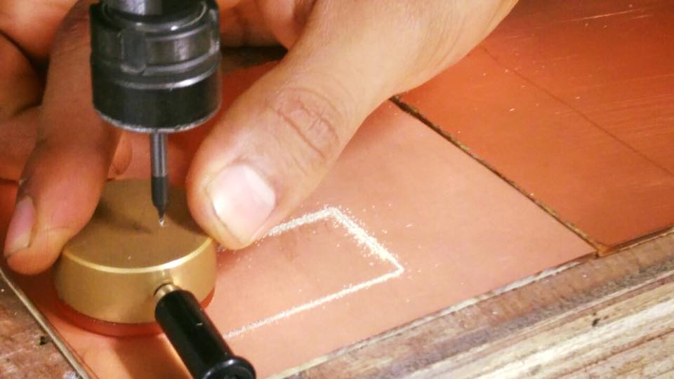
- Then the axes must be set. (X,Y,Z)
-For “X” and “Y”, the control can be use, so the machine stats working where we set the material on the base.
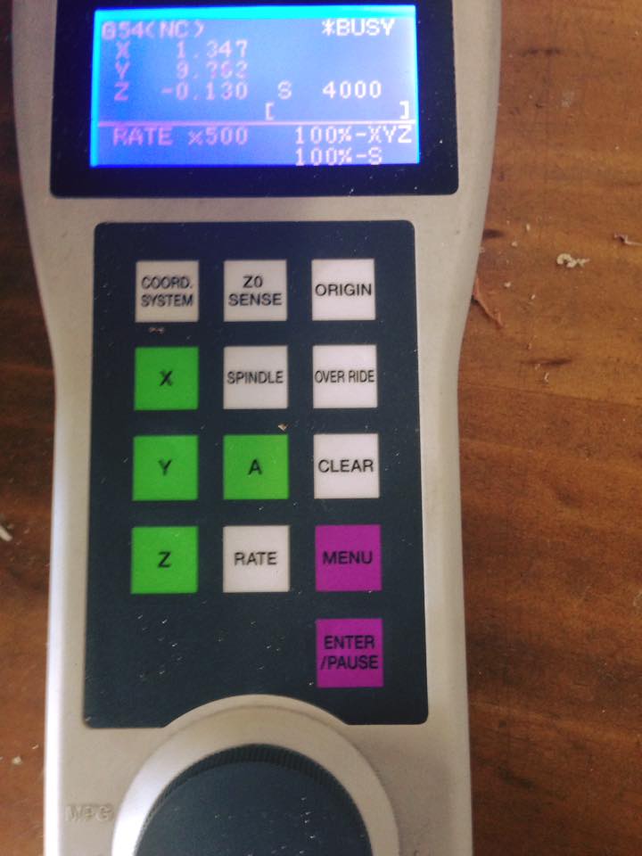
-For “Z”, which is how deep the machine must go.
To star using the Modela, it needs asoftware to translate and load the Gcode to the Modela.
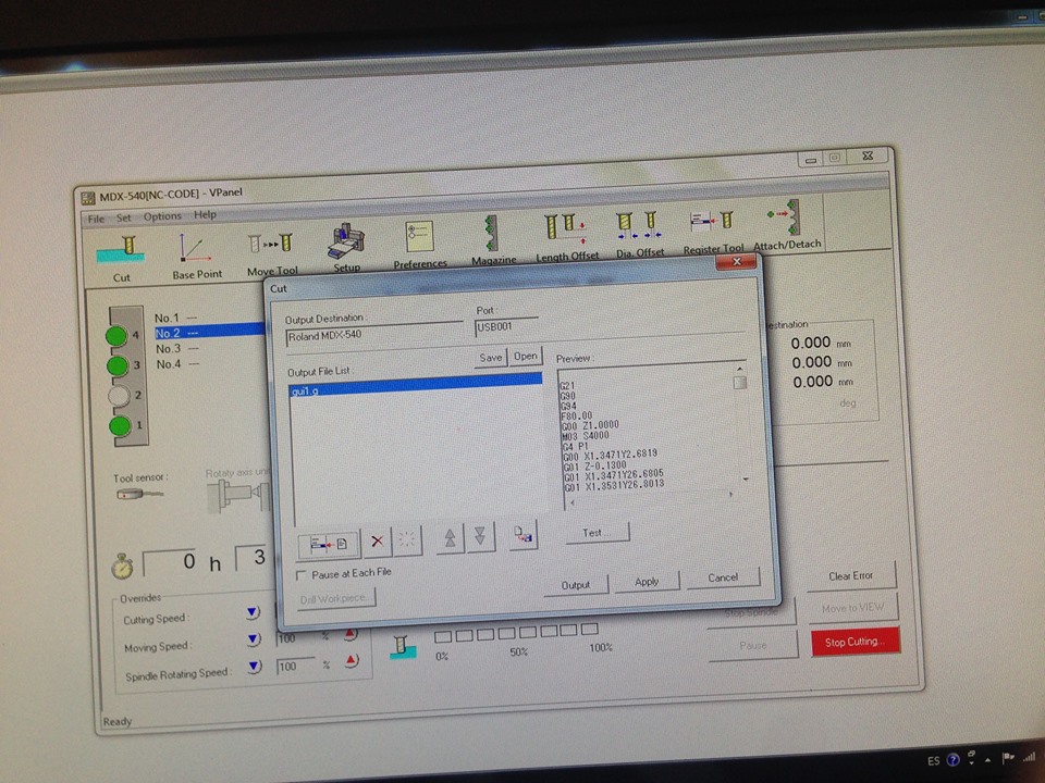
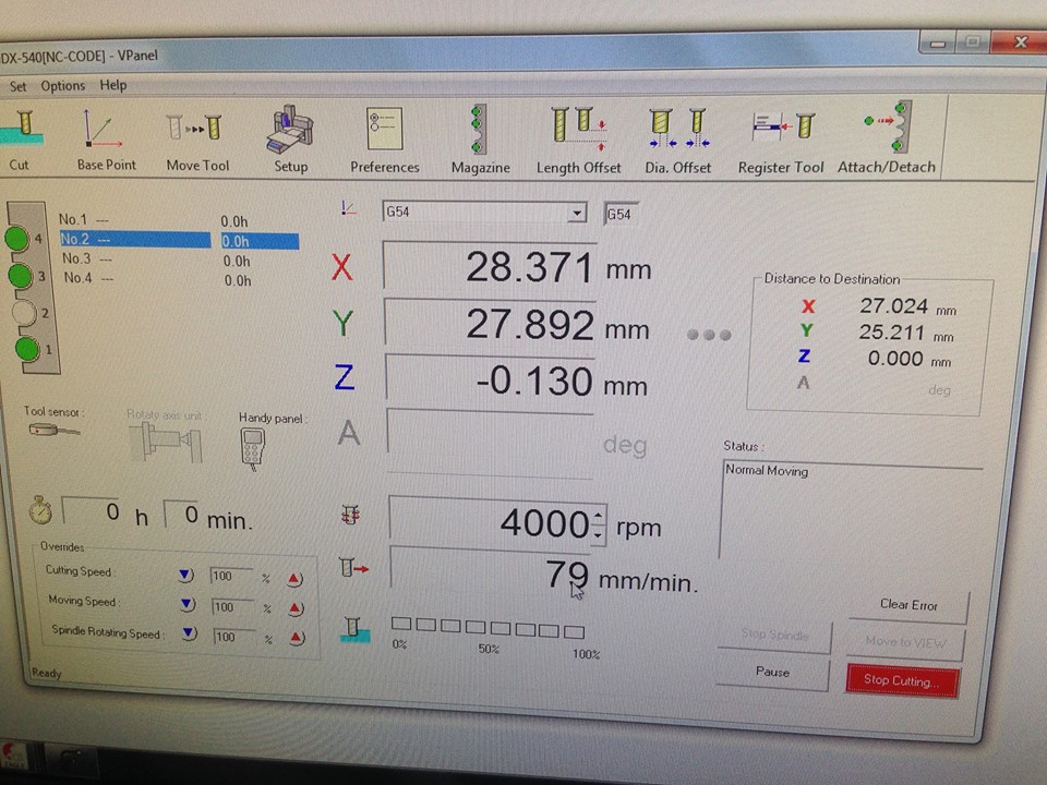
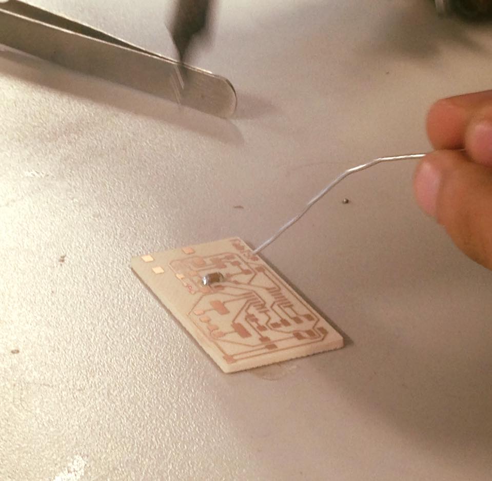
Then the milling starts.
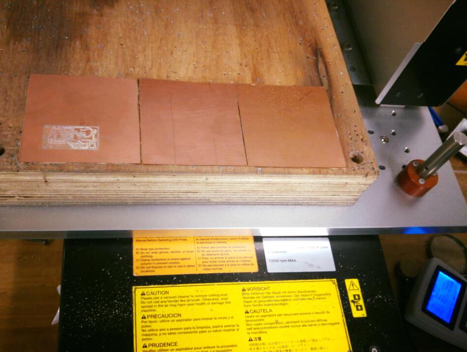
The first option was to use a FR1 kind of board, but it wasn´t flat so the milling wasn´t even. The second option, CEM1 worked much better. It´s very important that the boad and the base where the board goes be really even, if not, the milling work won´t do.
The welding part was actually the easier part for me, I used all the ítems in the list above, according the board map
First result:
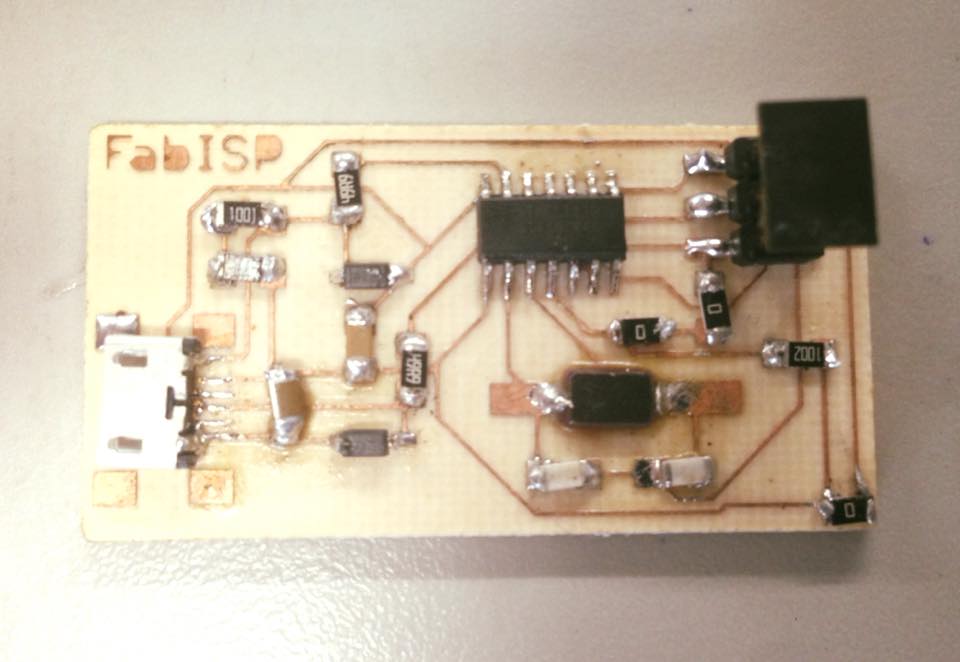
I plug it in the computer, but it didn´t recognize it. Then I changed two of the 0hmn resistances for jumpers and it did the trick.
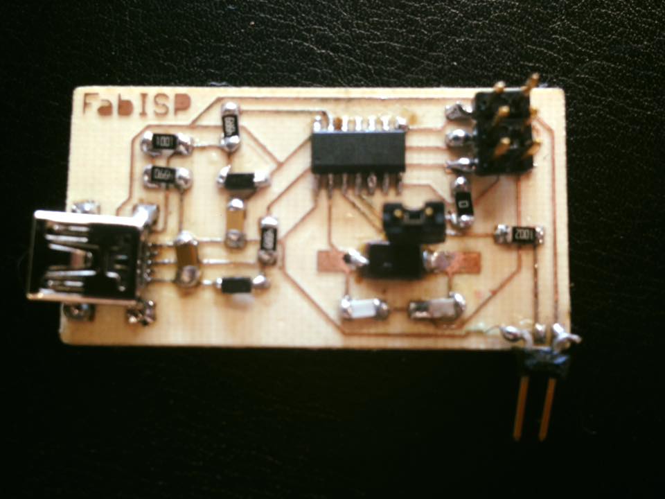
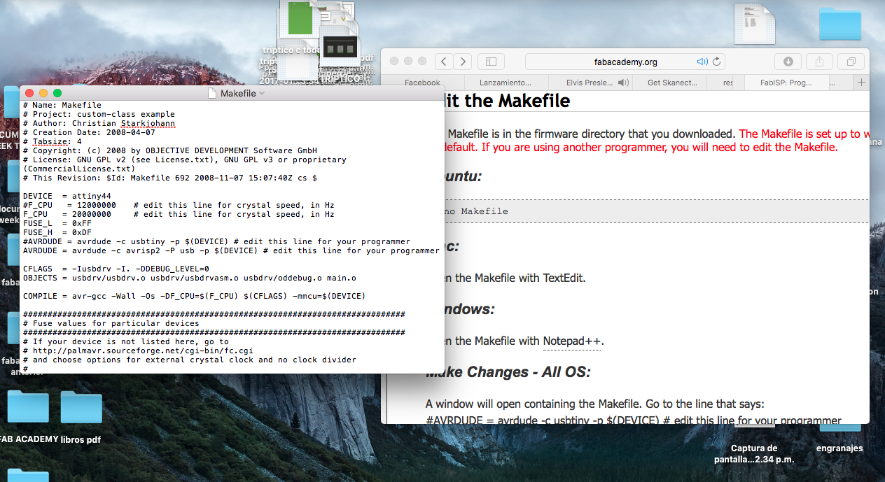
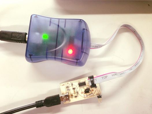
To finish the assignment, the ISP card must be programmed so it can program other cards later.
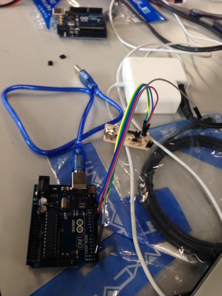
I tried it on Arduino One, but it didn´t recognize it.
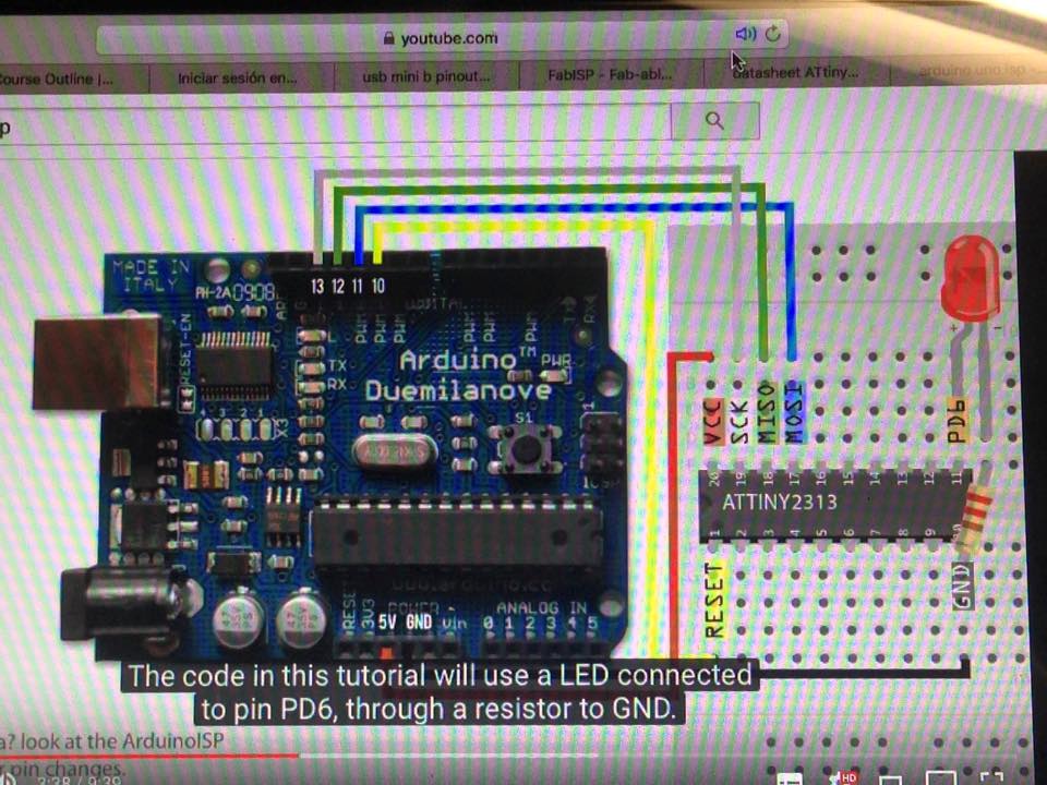
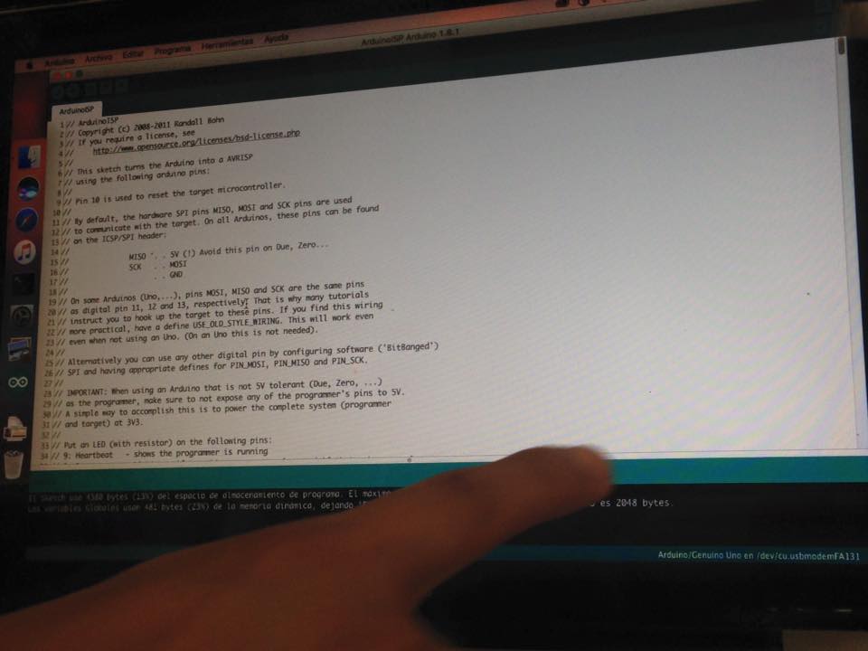
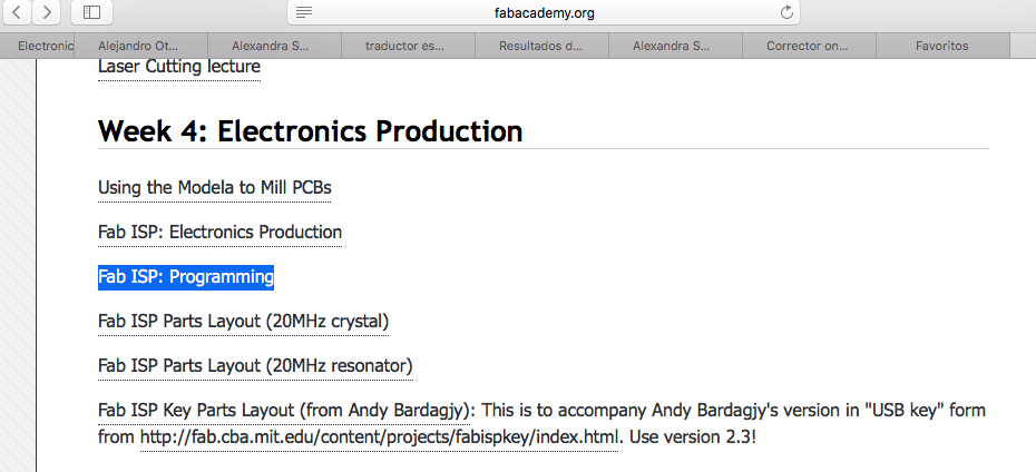
Then I followed the tutorial for Mac on fabacademy.org which include installing Crosspack AVR.
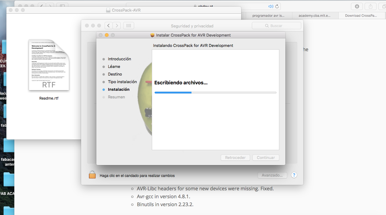
And it worked:.
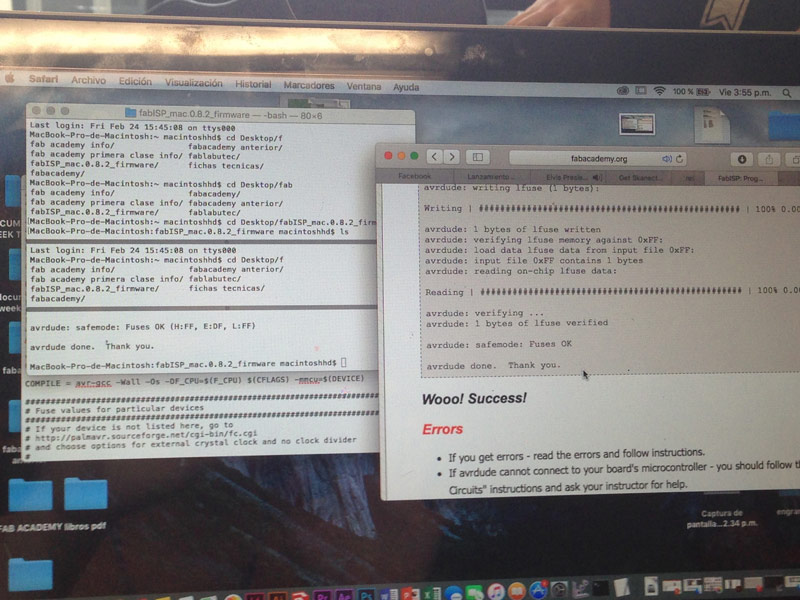
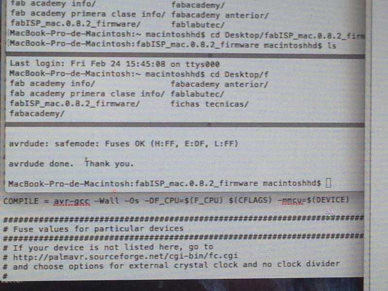
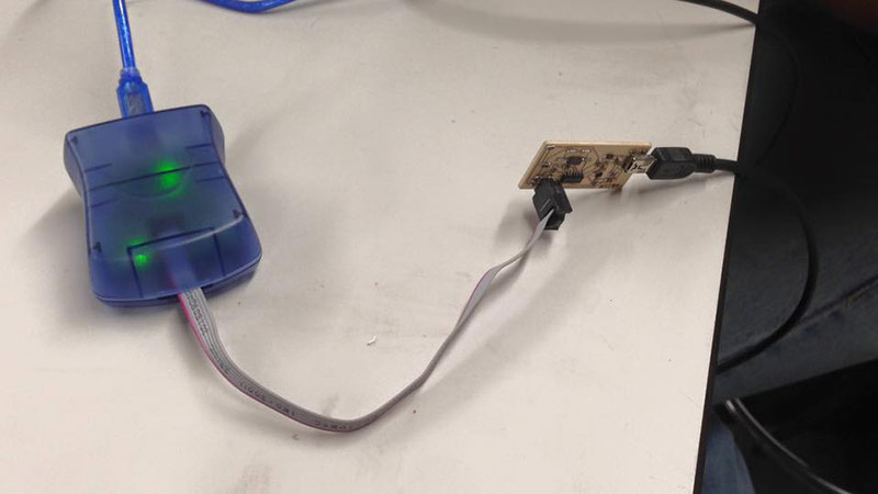
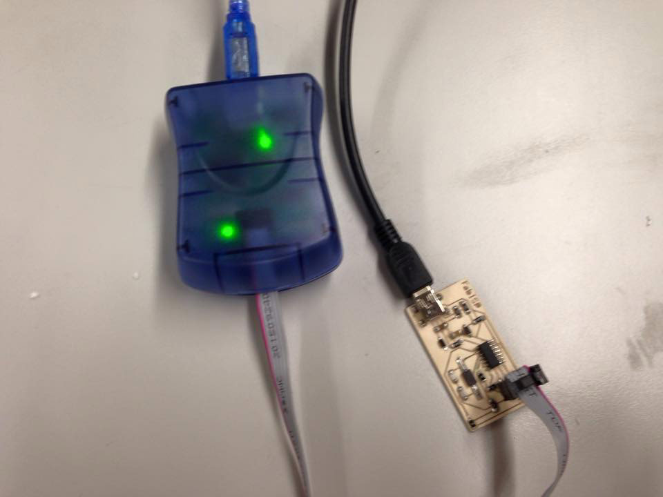
Done!!!!!!!