Make lasercutter test part(s), varying slot dimensions using parametric functions, testing your laser kerf & cutting settings (group project)
Cut something on the vinylcutter.
Design, make, and document a parametric press-fit construction kit, accounting for the lasercutter kerf, which can be assembled in multiple ways.
I wanted to see what happened if i used those magnets like the ones from pizza you put on the refrigerator.
I remembered a computer game called “pipe dream” so i tried to make a versión of it that you can arrange.
So I first designed the pieces in illustrator making sure there were no extra or open lines and putting the lines in 0.1 stoke. I also designed a water splash so it can go at the end of the pipes.
To print I exported the file to Corel Draw. The magnet paper came in white, which didn´t work for a white refrigerator, so i decided to raster the shapes to loose the white. First, I did test the find velocity and power combination to cut and raster. In doing so, I found that the paper had to be fixed with tape and put over a piece of Wood to work better.
The magnet paper document was 60x90 cm so it was very large for a full raster work, it took more than four hours just to raster. In the middle of the process, we had to leave and turn off the machine. Even with out moving anything and restarting the next morning, there was a darker line in the water splash piece (the bigger one). In Corel, the inside of the figures had to be painted in black so the machine raster
After it was done, the black was erased and changed to a fine line to start the cutting.
It worked better with black
Fort he vinyl cutting part of the assignment, I decided to continue with the “pipes” theme, but this time using paper to make a three piece connecting print, each one in three layers.
So, again, I started with Illustrator, designing each layer...
I had to modify how thick the line was. In difference of the laser cutting machine, for the vinyl one if the line isn´t thick enough the file won´t be read. First, with the help of the lab mentor, we tried using the machine own software, but it wasn´t recognizing the document. Even when trying in different formats. After that, we tried fabmodules, it even recognized the path it had to follow for the cutting but then nothing. So, the machine it has been checked to try again.
First I did a Little test cutting an image
Then I set it to print the actual work
First, it has to meassure the size of the paper that its going to work with.
Selecting piece, it meassuares how wide and long the paper is. If you are working with a material in a roll, it can be set up for that too. With the meassures, the canvas can be set to arrange the pieces in the paper.
And send it to work
I sent three files, the “C” file (Green paper) which was the easier, end up ok
The “B” file, which was the more detail file took hours to do and because the cutting parts were so small, I think they needed more streng. Texture was created but it didn´t make the cut
I had to take the Little circules out with a needle
The “A” file, the one with the pipes was eaten by the cutting machine, so it had to be done again.
For hanging, I cutted in the laser machine acrilic and MDF Wood.
With two pieces of two layers (without the “A” file) It looks like this:
Thinking about the “Something Big” assignment, I decided to make an scale model of the design I´m going to build on that week.
The idea is to create a three piece structure, that combined can make different kinds of furniture as a bench, table, etc.
For this ill design a parametric press fit piece that should work as a unión of the modules. This pieces have been designed on illustrator considering the thikness of the MDF, in this case 3mm. If/when the material change, those parameters can be arranged to the new characteristics.
With the result, i built:
I found in the fab Barcelona web, a series of designs for laser cutting made so you don´t have to saw.
I re-draw some of them on Illustrator and made a test on the laser machine:
With that I went to the laser machine and made some test:
The settings for this fabric-foam material are:
Testing:
From the tests I chose this one:
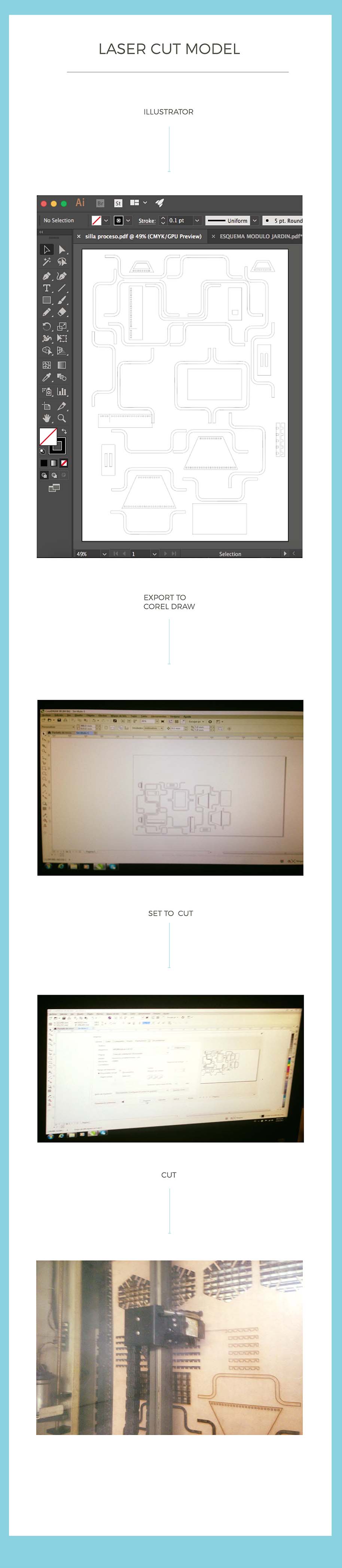
Finally, I decided to try FUSION 360, from Autodesk, to make the parametric design. I found this tutorial on youtube:
https://www.youtube.com/watch?v=PwVRaWxW7F0Which gave me the main idea of how the software works.
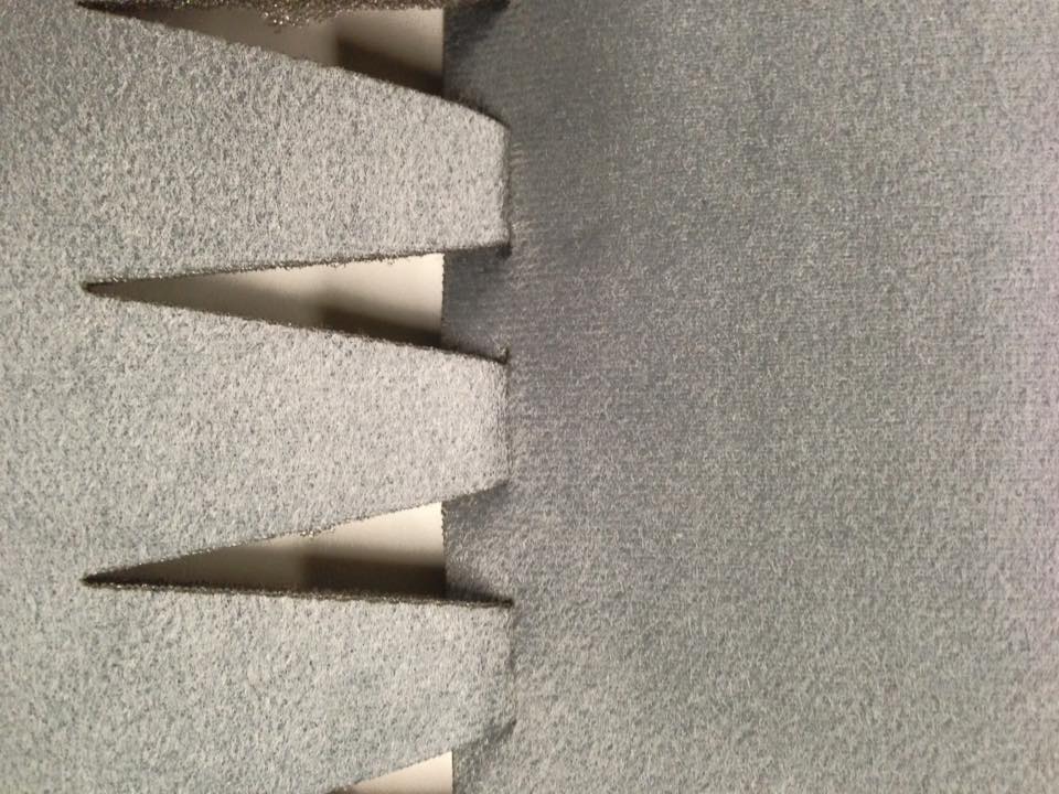
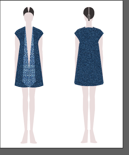
Because I´m a fashion designer, the idea of paremetric design apply to patterns sounds interesting. I decided to prove with a simple pattern of a rope, but with the fitting shapes done earlier so the pieces can be fit together without sewing.
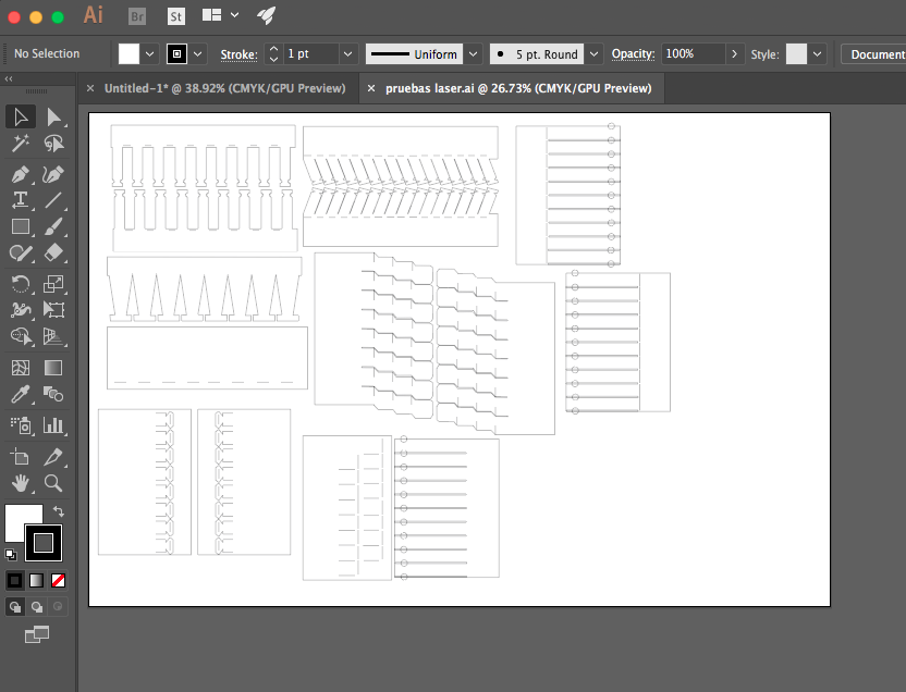
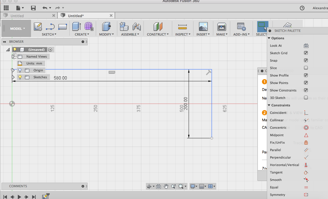
With that idea, I started on Fusion 360.
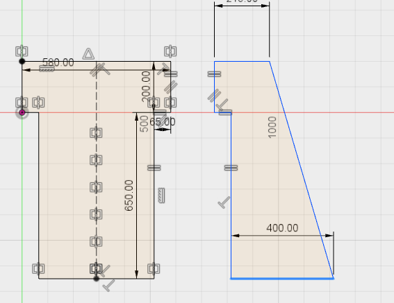
I started making two lines, the good thing about parametric design is that you can arrange the behavior of the lines to adapt to the changes in the design. For example, because of the design I needed this lines to be perpendicular. Even if the distance changes because of the size of the piece I want to make, this lines should always be perpendicular, this can be achived by selecting both lines and clicking on the side where it says “perpendicular” . Like this, you can also arrange for the lines to be in paralel, tangent, etc.
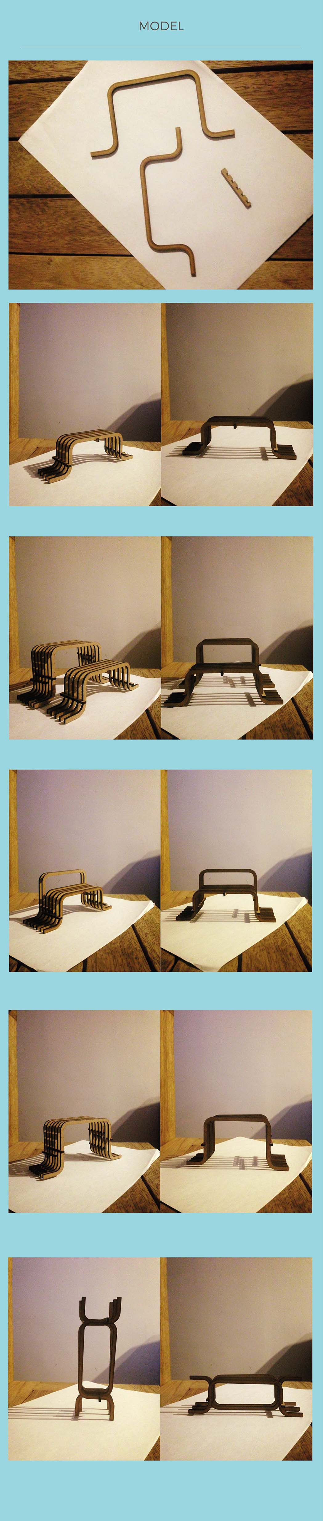
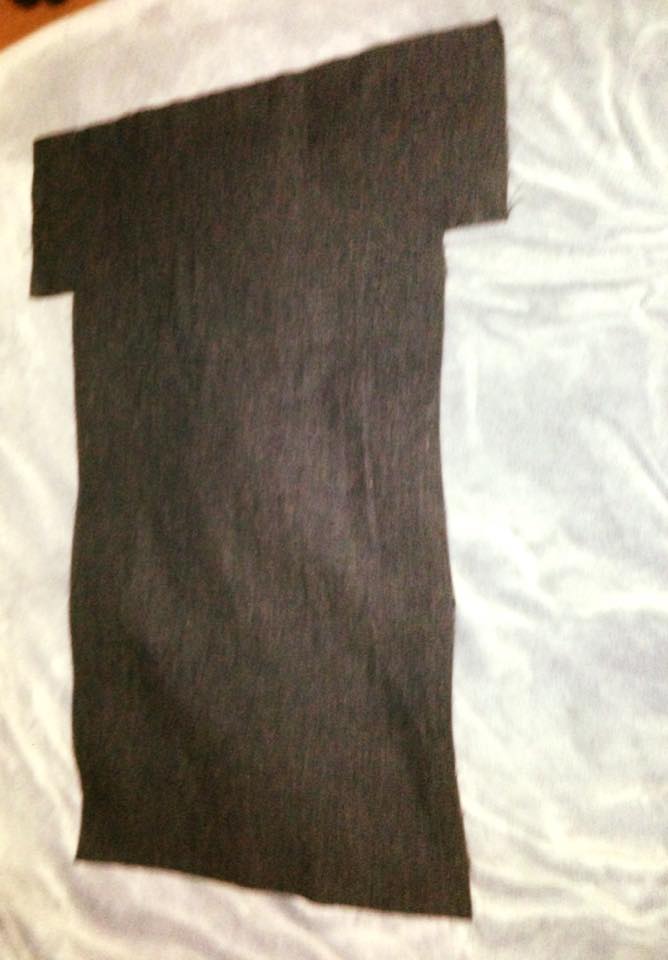
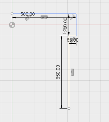
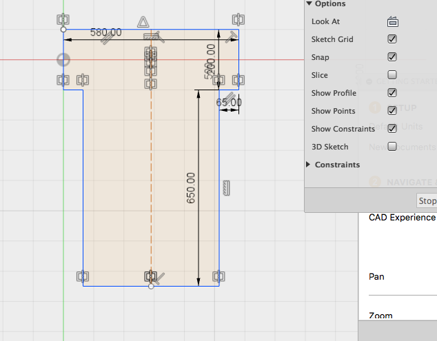
I started with the back :
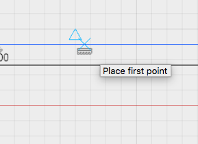
To find the center of a segment, the mouse must be move on the line. When the triangle and X appears, It means that is the center, like in the picture:
If the line is prolonged to the end of other line it serves as a reference point to know how long the line must be:
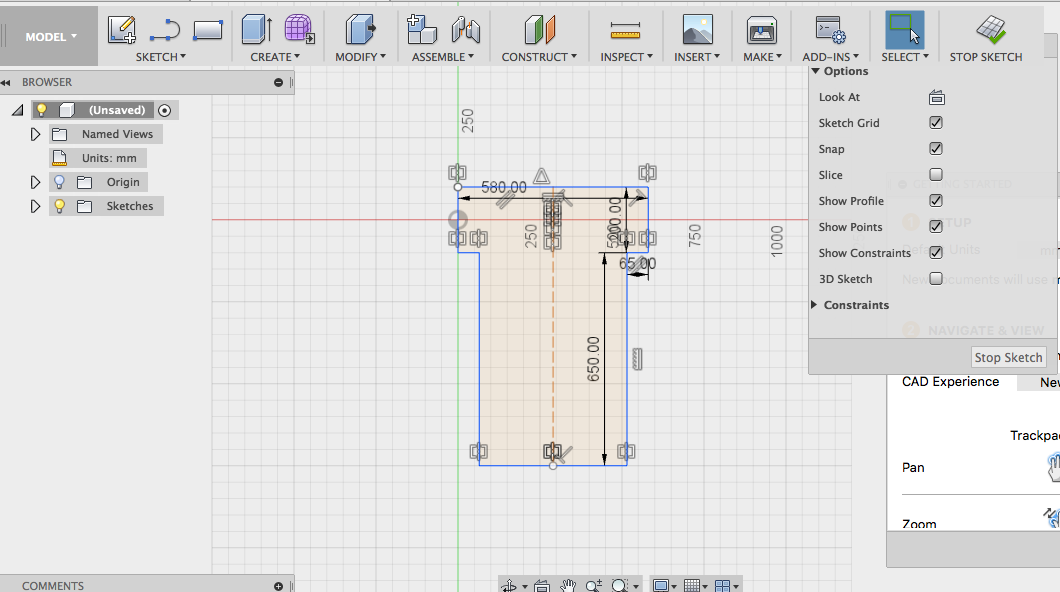
There are also guide lines , selecting the line and clicking on “Normal/Construction”.
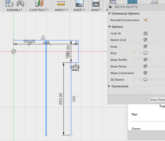
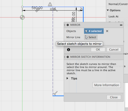
Selecting the pieces and coping and mirror the lines is a possibility to work faster.
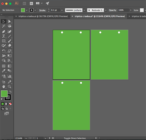
Fort he front, Ill have to cut to pieces, but I plan to do it in just one cut putting Two pieces of fabric together facing each other. That way I´ll have two pieces in just one cut saving operating machine time.
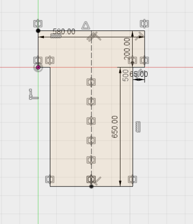
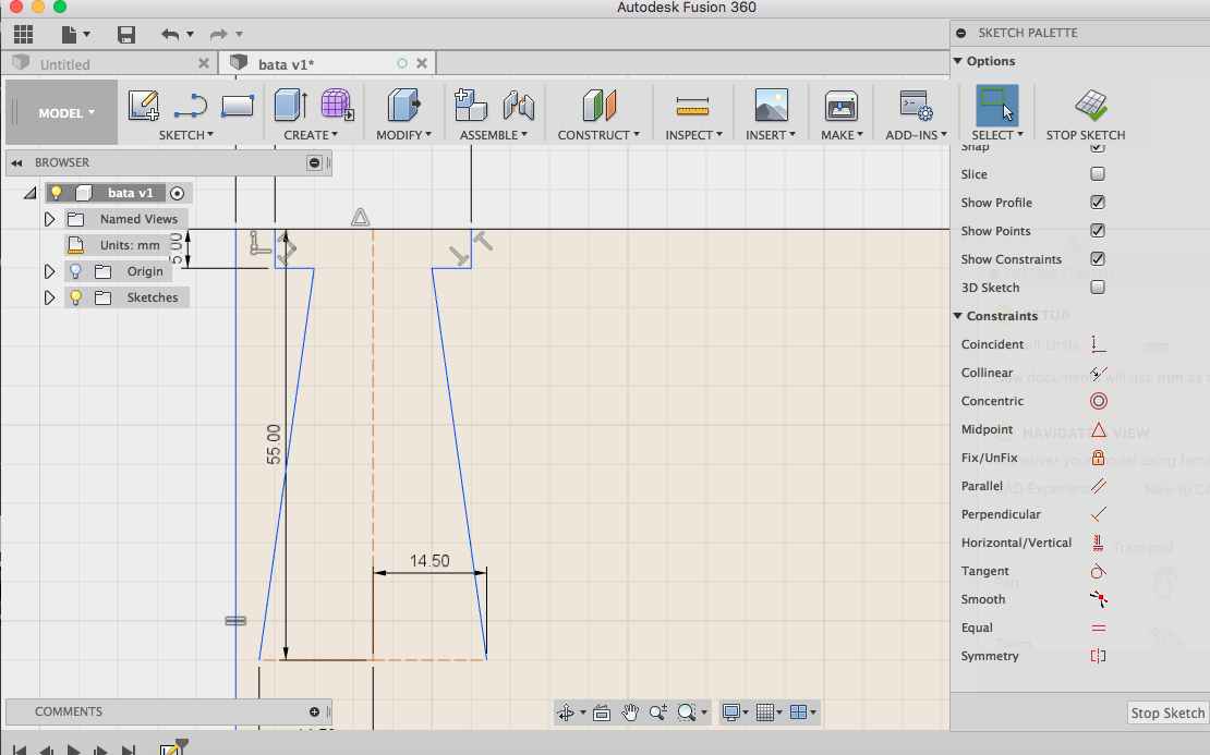
An stimated look a like line can be draw and select the line you want this new one to be like so it copy it. Makes it good for fitting patterns.
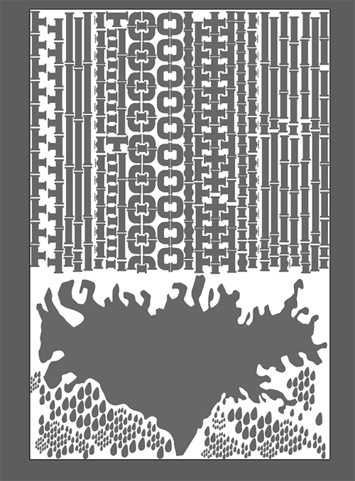
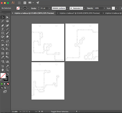
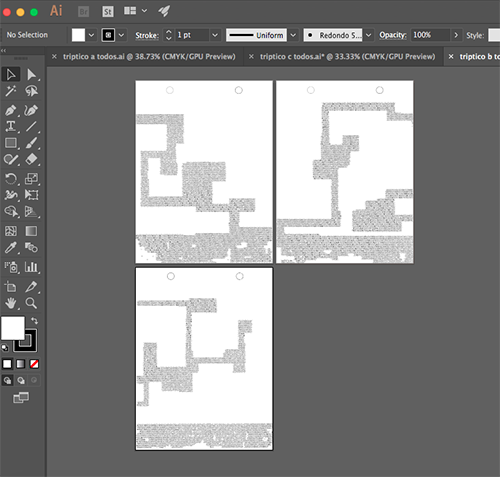
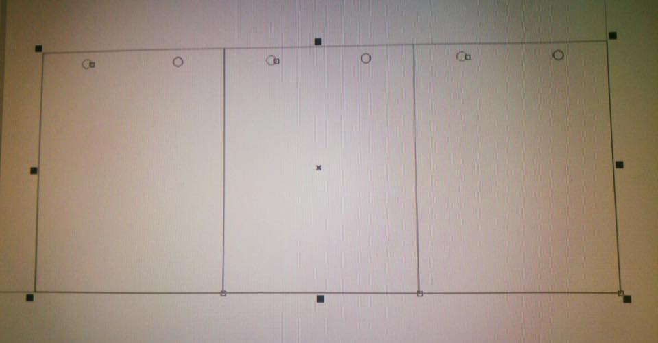
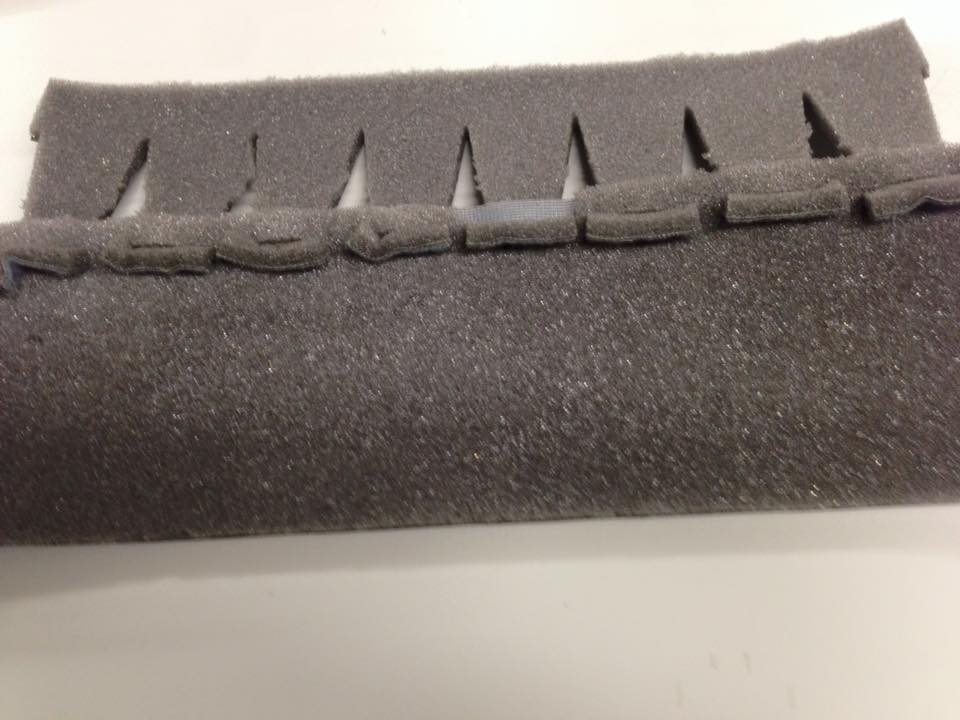
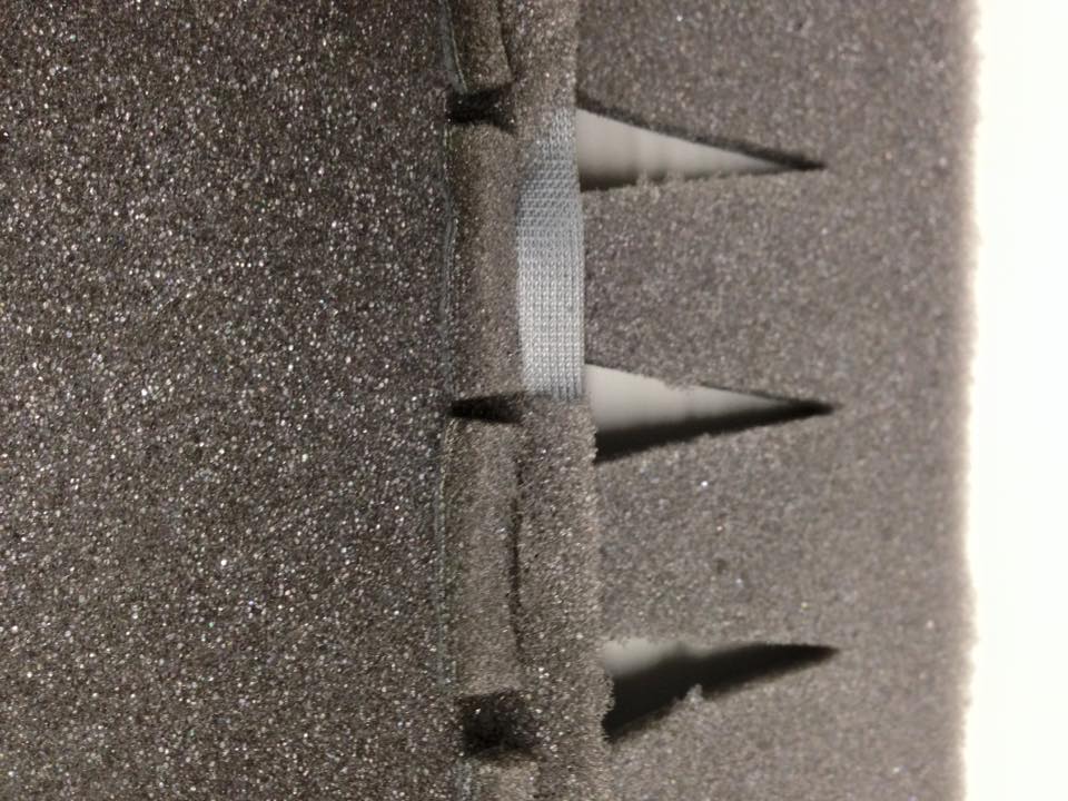
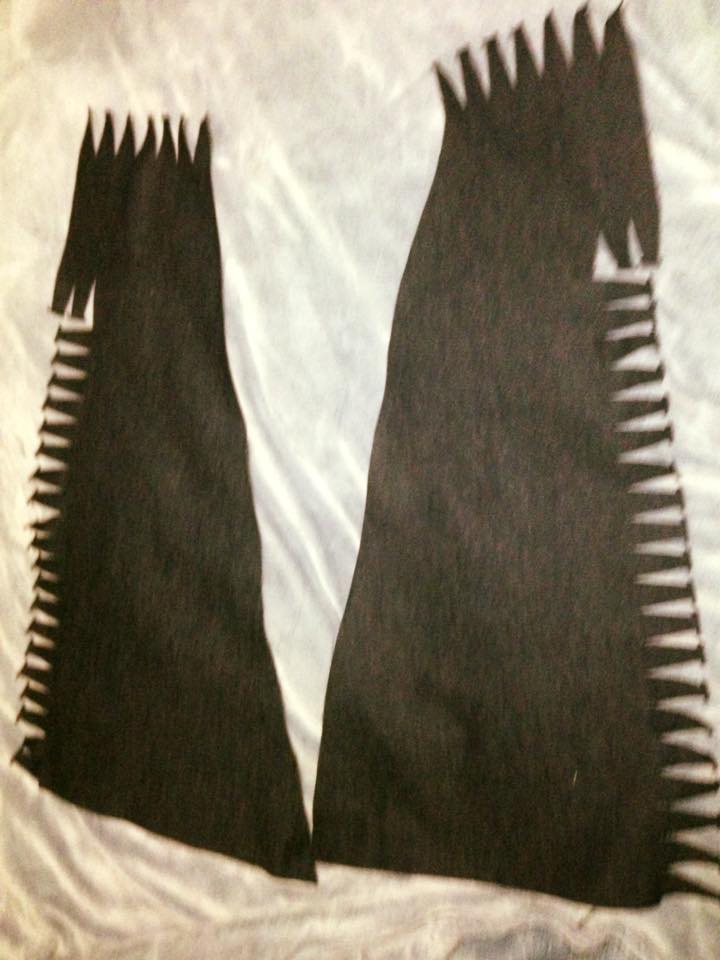
Then I drew the module of the fitting parts and repeated it in a pattern through the needed area.
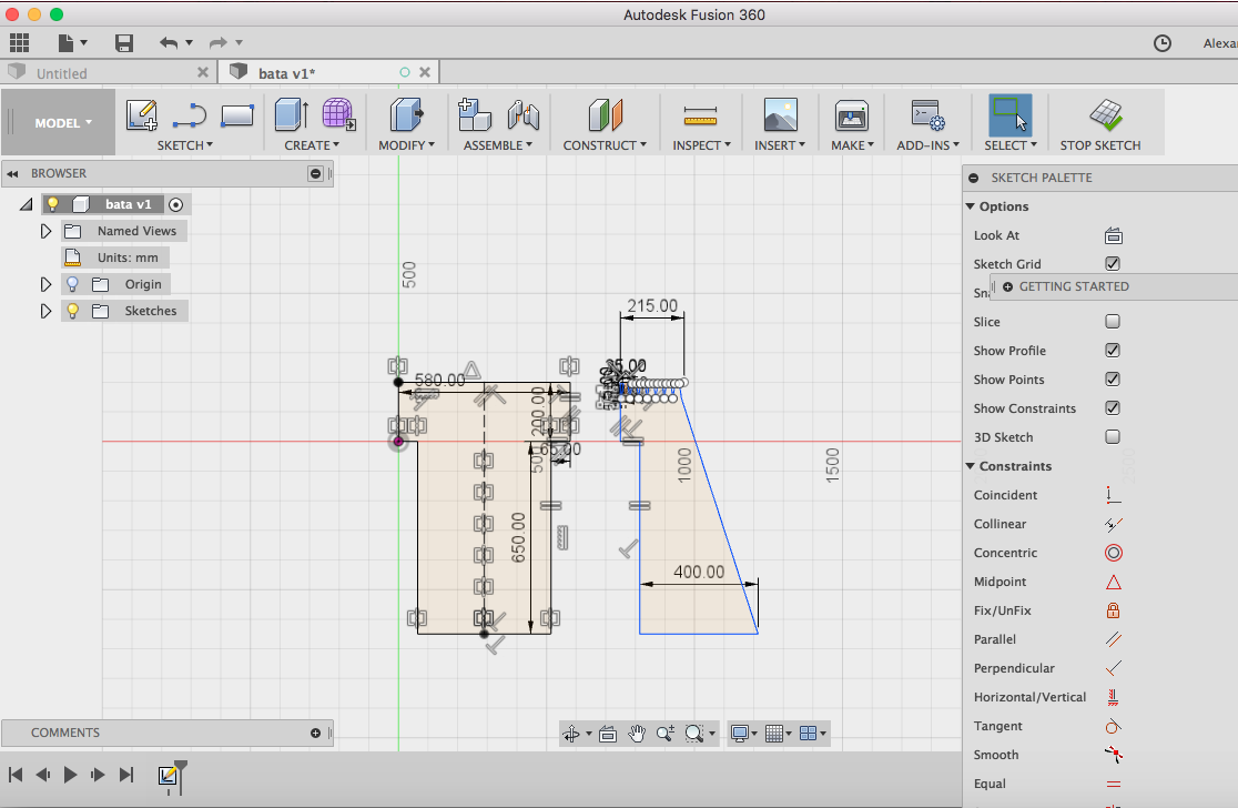
Did the other part of the fitting pattern as well.
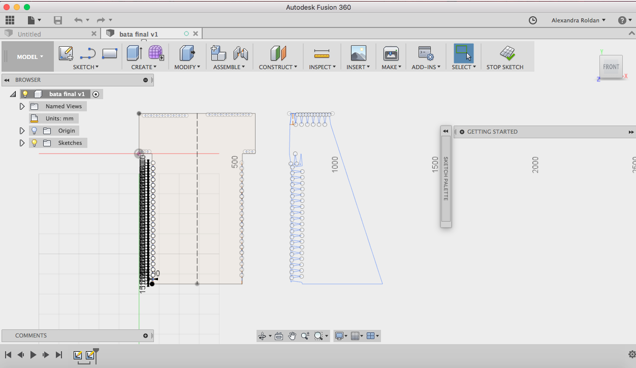
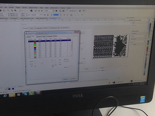
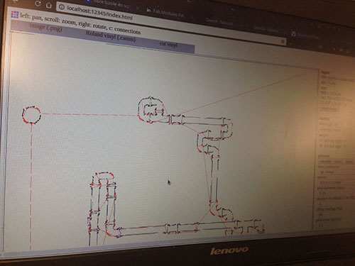
With that the file is ready to cut.
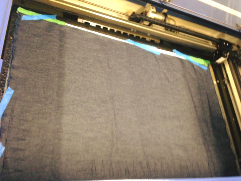
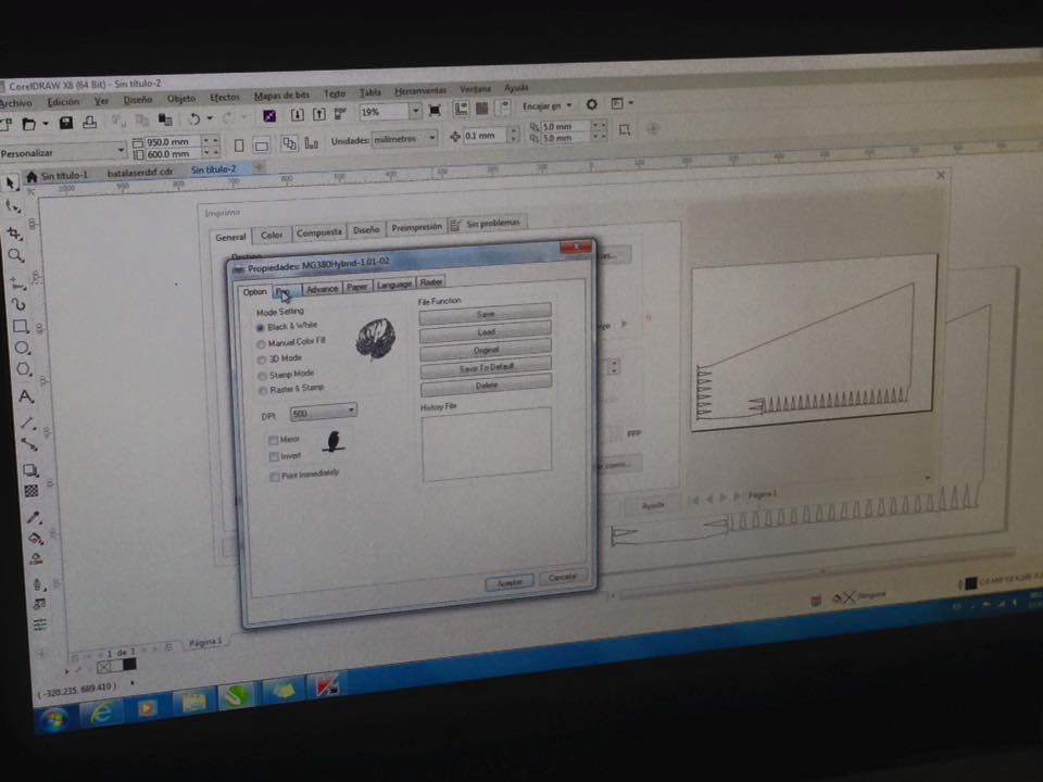
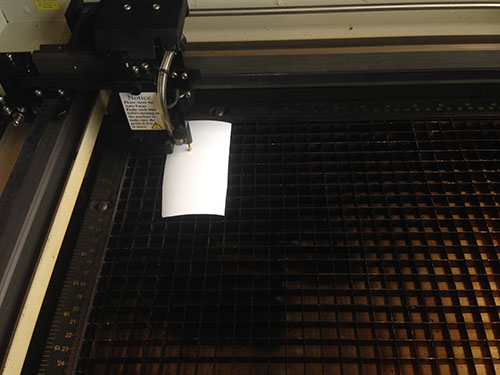
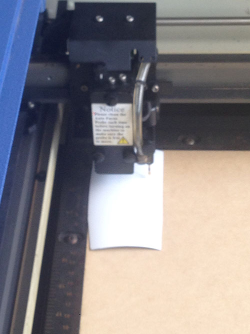
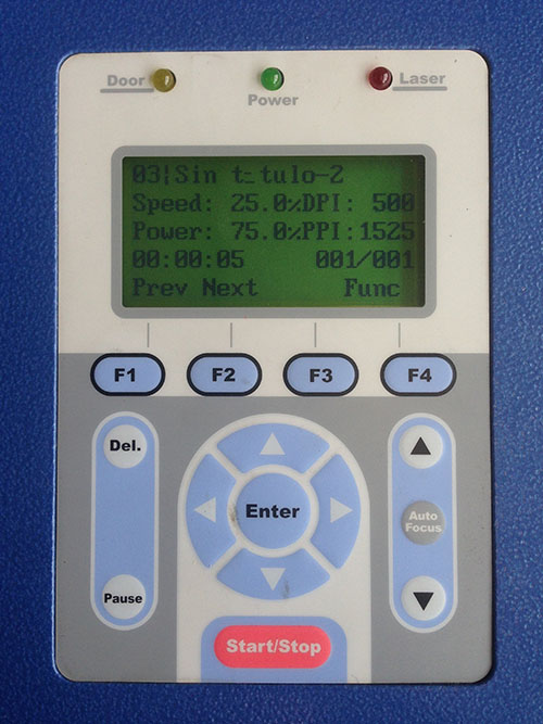
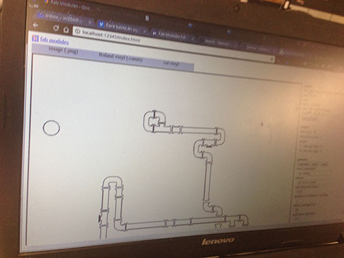
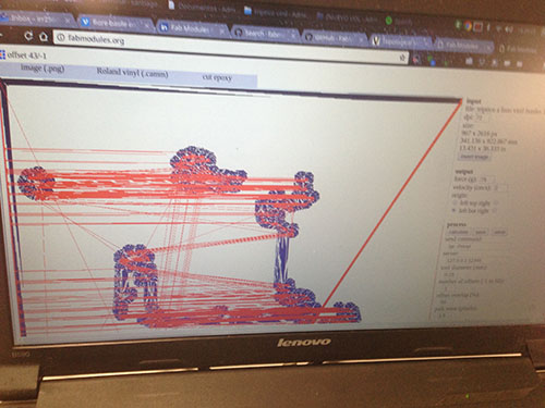
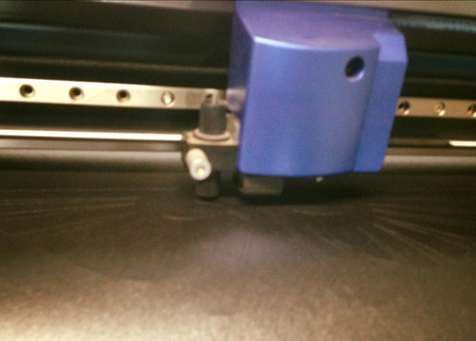
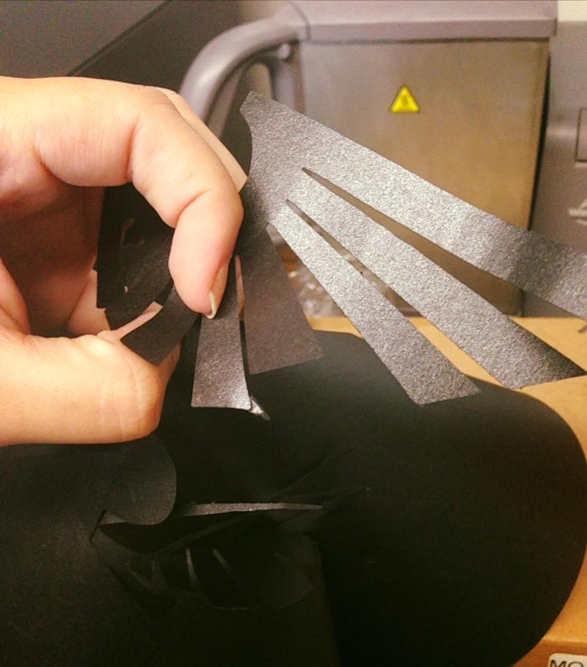
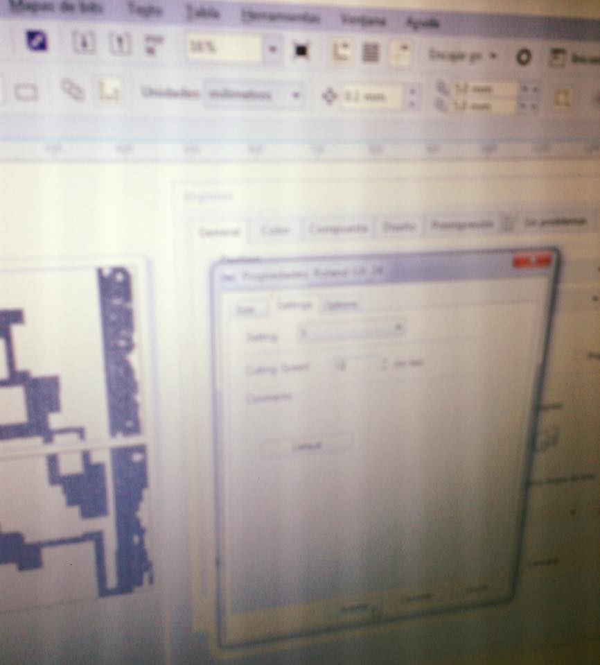
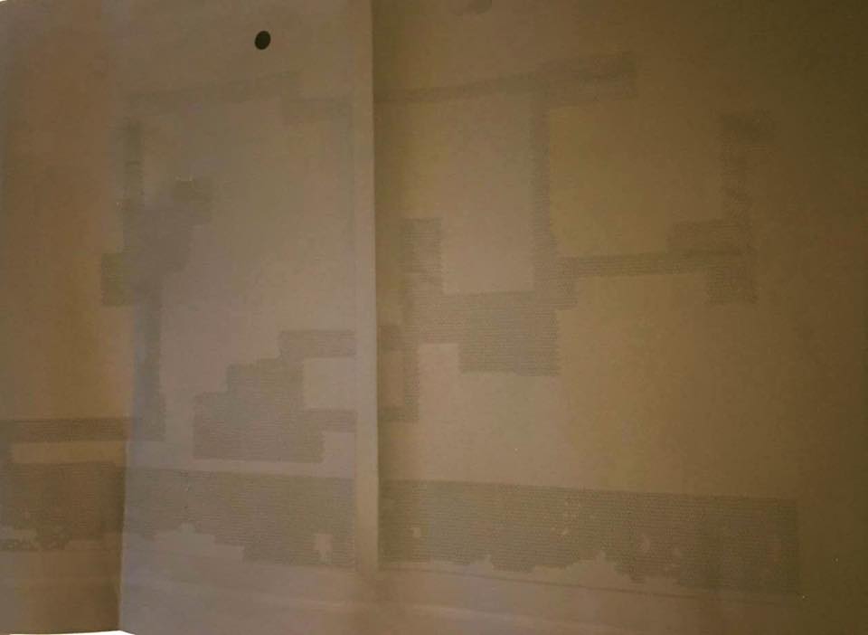
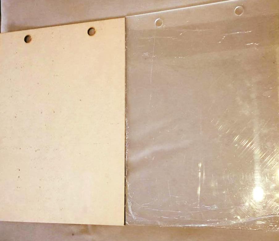
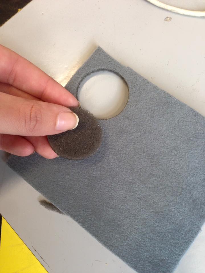
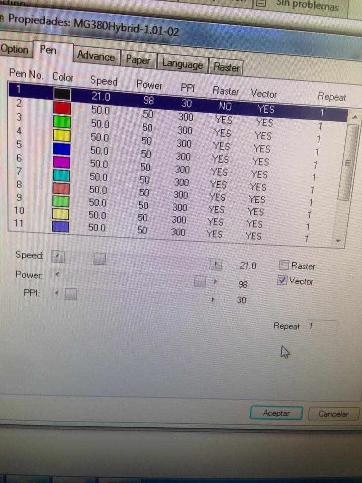
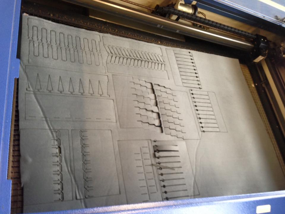
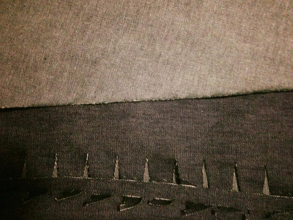
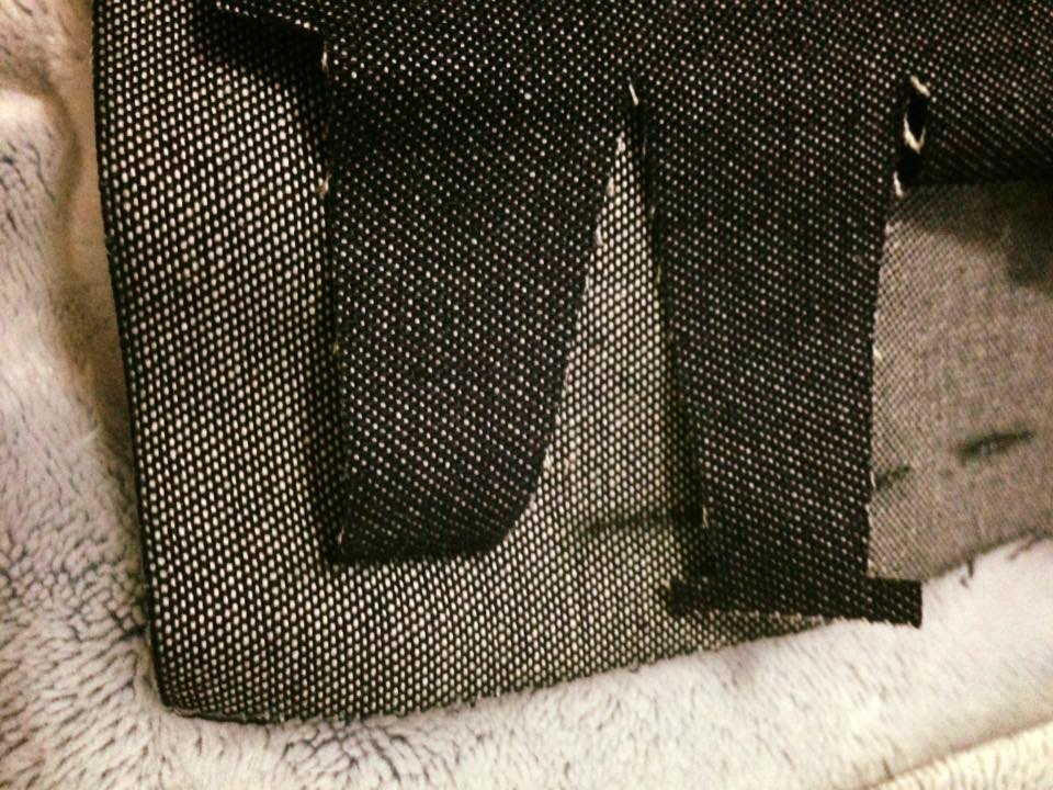
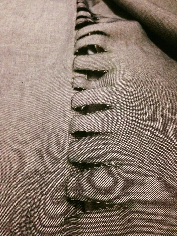
To figure which parameters where better for cutting this denin fabric, I made some tests:
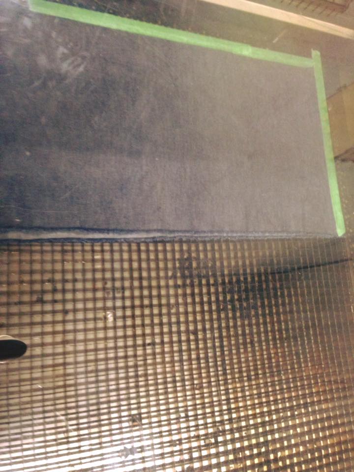
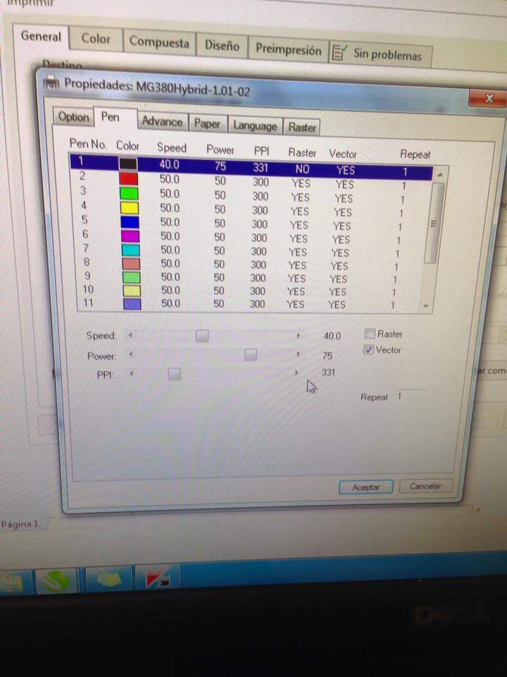
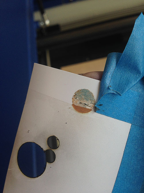
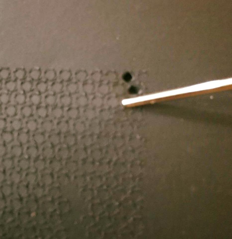
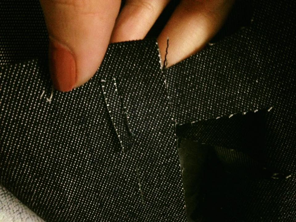
Because it didn´t cut through well enough, the parameters had to be modify:
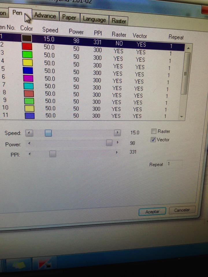
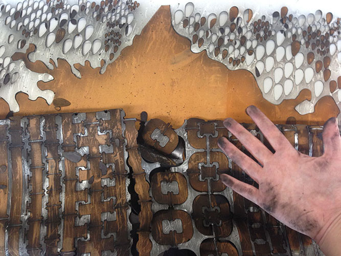
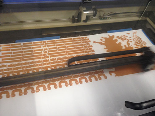
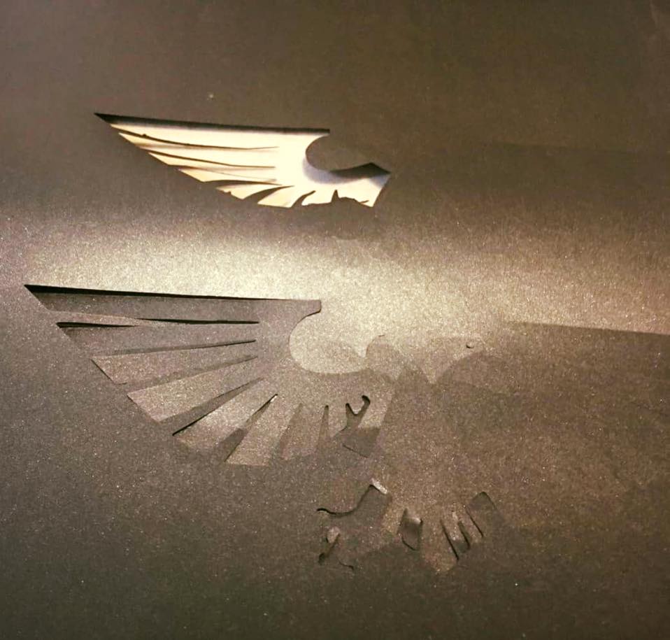
With that the result on test was ok:
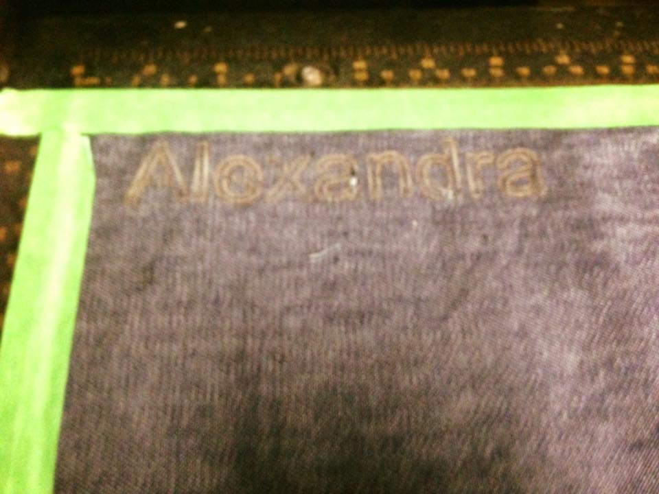
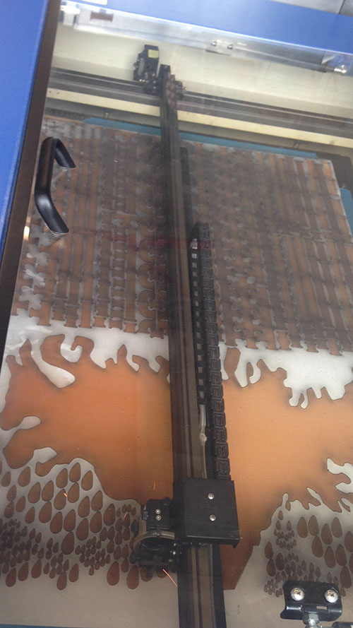
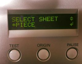
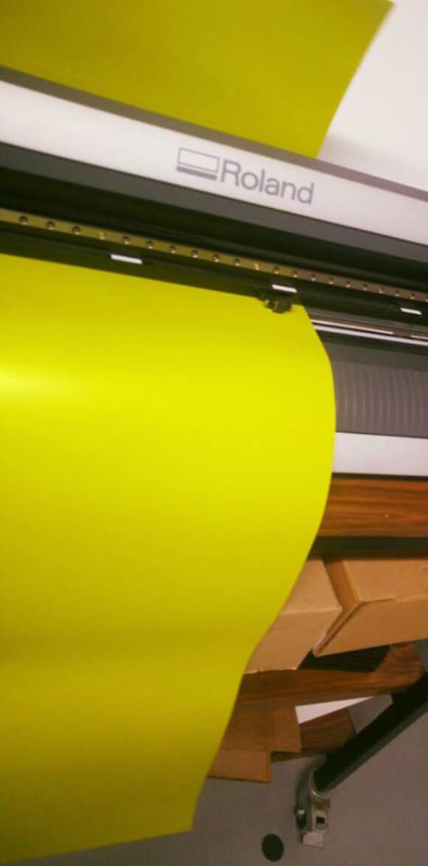
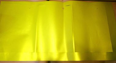
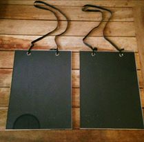
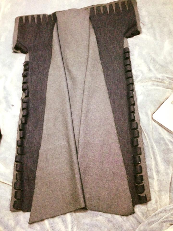
So, I proceeded to the piece cutting:
It cutted the fabric very fast and the result was very good
Because of the parametric design, the pieces fitted perfectlty-