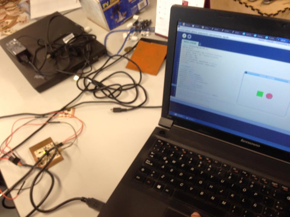
For this week, we have to write an application that interfaces with an input &/or output devide that you made.
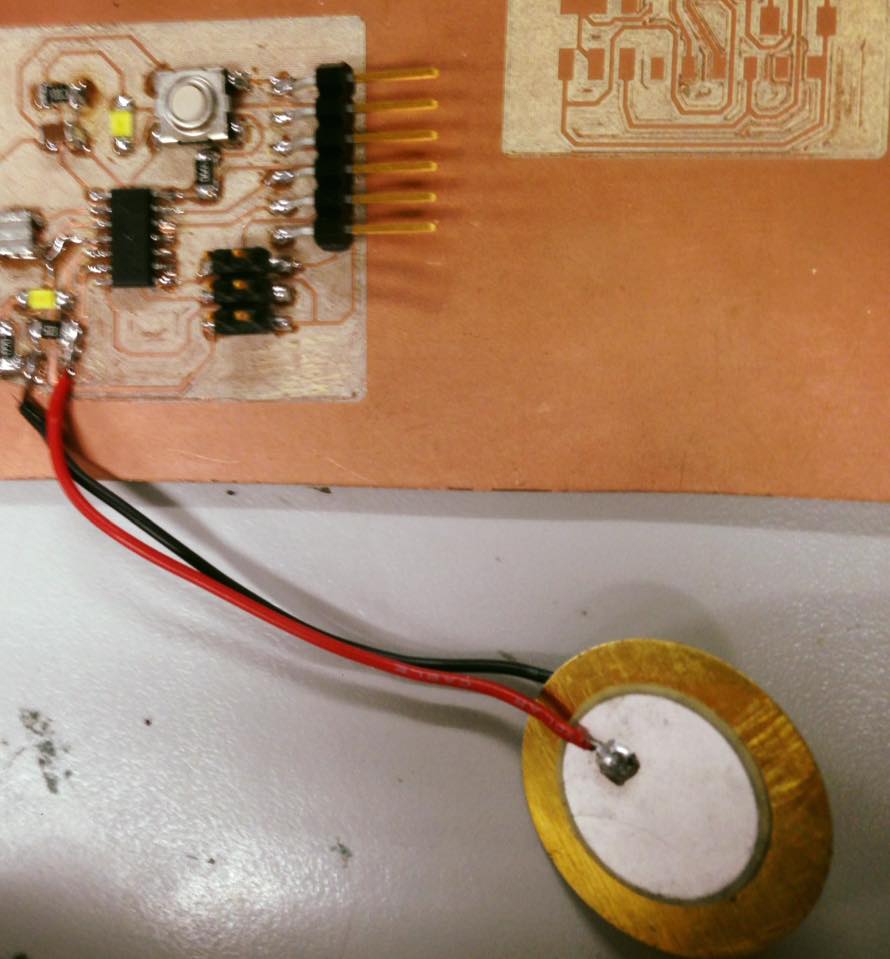
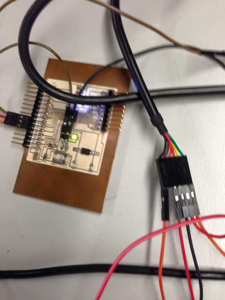
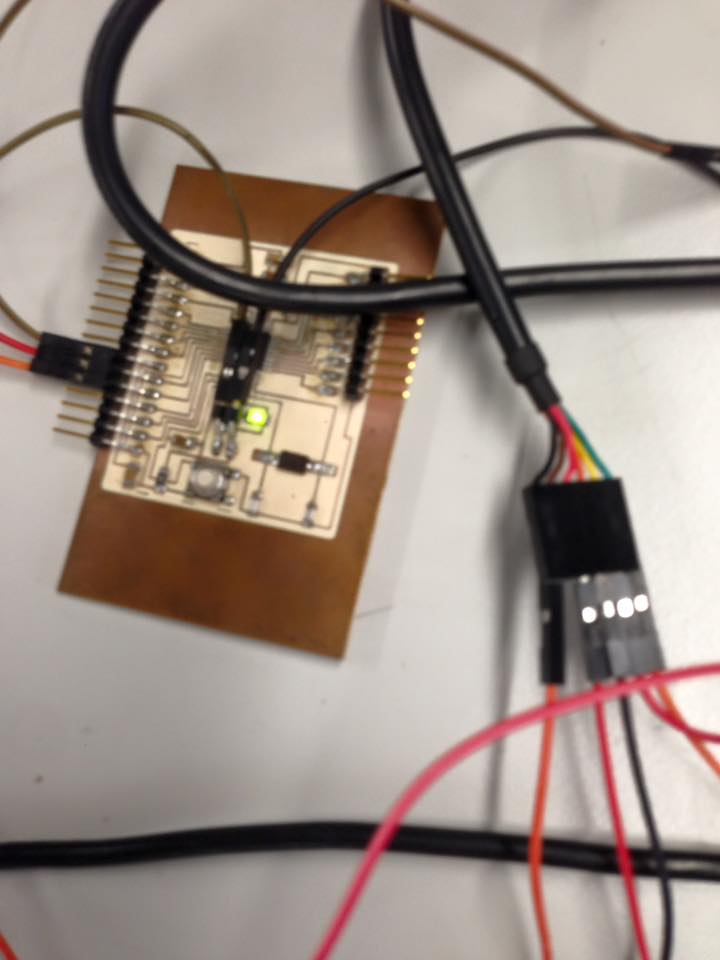
I modified a hello board to work with a piezo electric sensor as an input.
So for this assignment I used Processing:
It can be downloaded here:
https://processing.org
The idea is with the modified hello board with a Piezo Electric input.
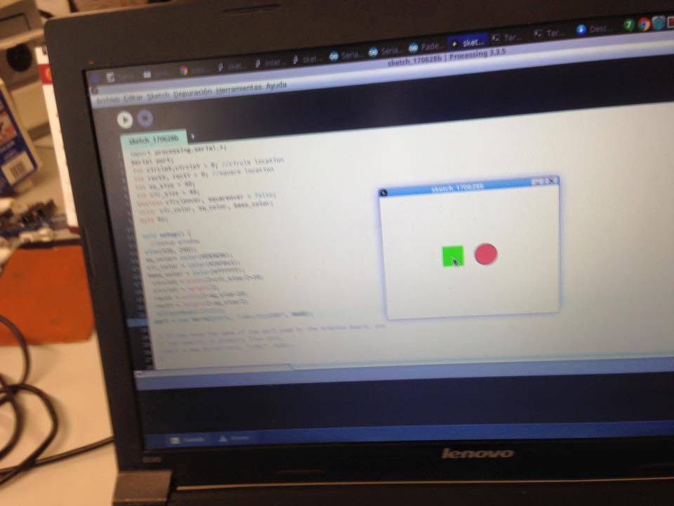
Create a code in processing with two buttons of the leds colors that reacts.
When the piezo electrics recive a signal.
For that, I first looked up for an existing processing code for buttons.
I found one in this adress:
https://processing.org/examples/button.html
Looked like this:

ARDUINO
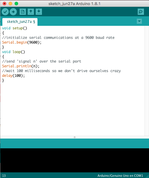
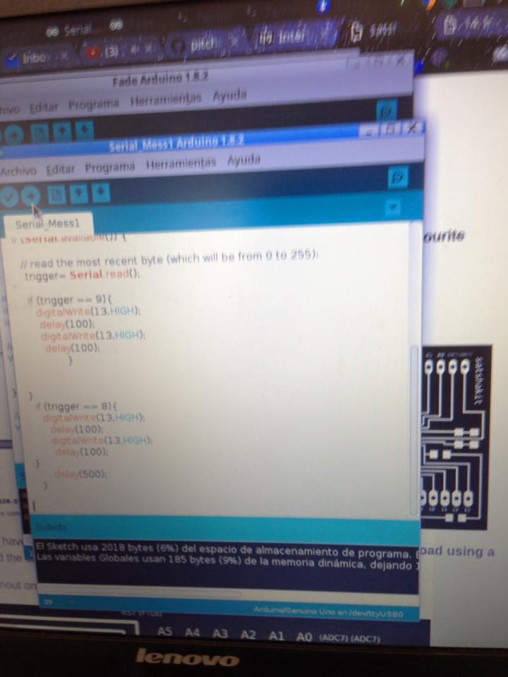
To comunicate the board with the piezo electric and the processing an Arduino code must be made. This arduino code has to be able to read a sign sent by a serial port.
On Alejandro´s web:
http://archive.fabacademy.org/archives/2017/fablabutec/students/161/
I found this tutorial about how to comunicate arduino and procesing.
The tutorial is:
https://learn.sparkfun.com/tutorials/connecting-arduino-to-processing
So the idea as I understand it is to write a code that tells the arduino that if the board with the piezo electric recives a signal, it must be sent through the port and wait.
With that the processing code will react to the sent signal and act.
I followed the Helloboard tutorial and changed the serial.println variable.
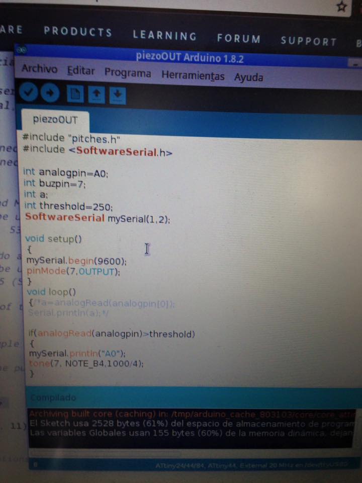
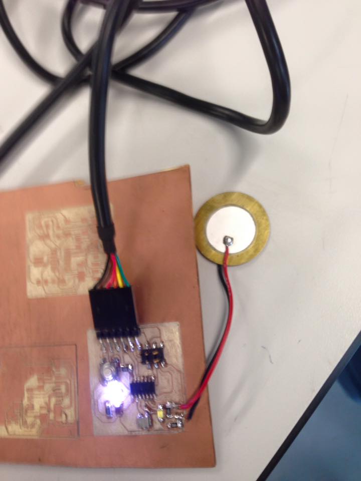
Now the code needs to recognize the piezoelectric board.
The board I did for the output week (10) is the same that would be use here.
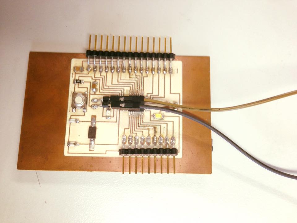
Then, I tryied with the original Satsha Kit I made weeks ago:
Then, the processing code will send a byte to the arduino.
After the code was compliled on the ARDUINO- SATSHA. The comunication began with the Processing code: Here is the result:
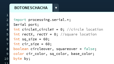
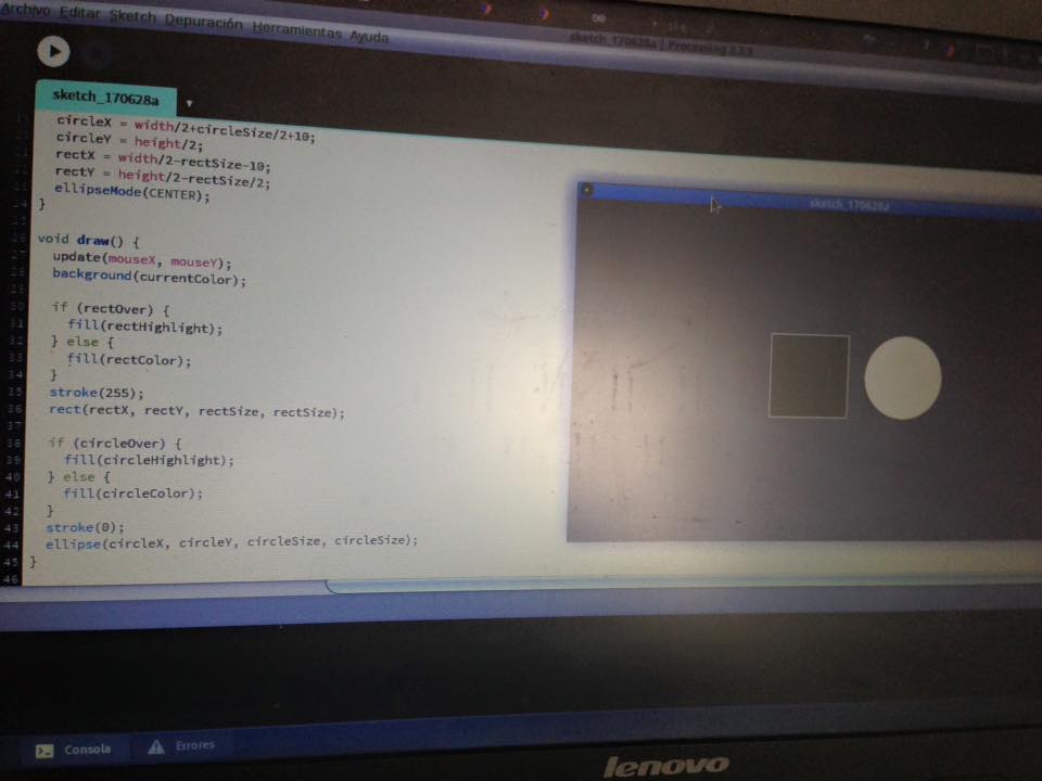
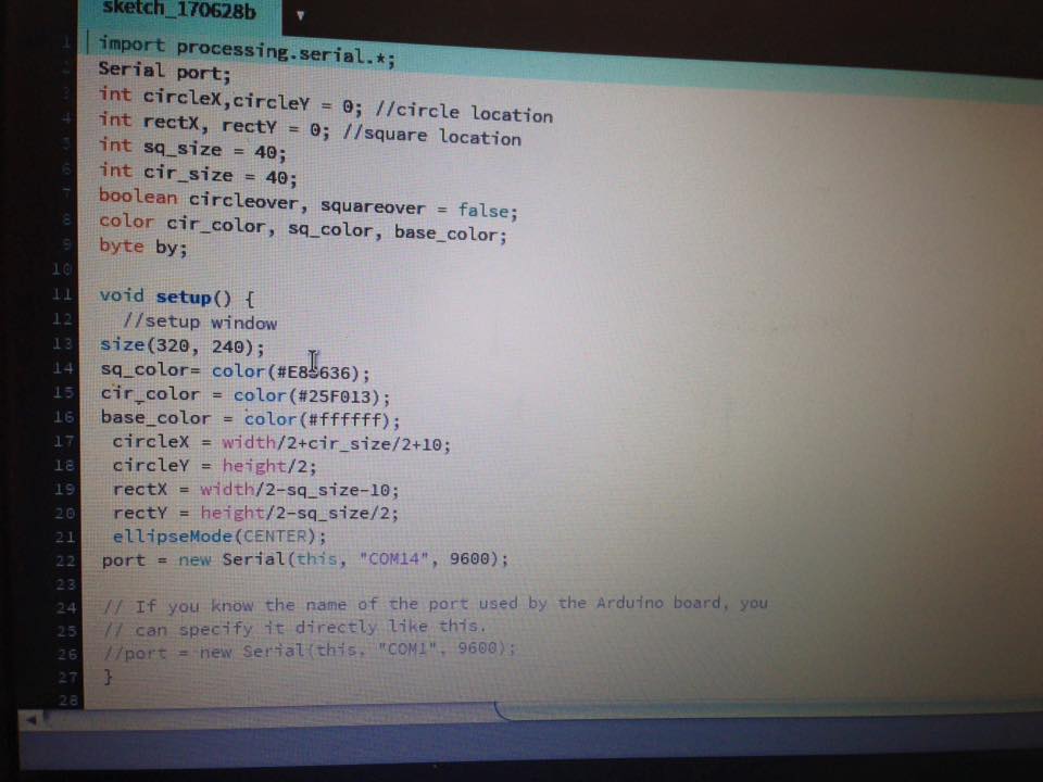
From the code I downloaded, I started modifying it.
The first part :
Int (variable): here you have to set the location of the form considering X and Y Axis.
And define byte by;
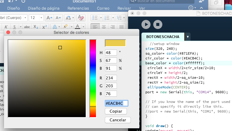
VOID SETUP()
In this part of the code you define the color and size of the figures.
For example, to change the color, you must go to : TOOLS- SELECT COLORS
And a window will appear to select the color and give you the color code, which you can copy and change for example in: cir_color= color ( )
This time I changed again for yellow and purple as you will see in the code.
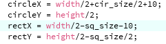
In this next part you configure the size, for example, yoy can divide the width of the figure /2 so from the place you set the figure it stays half to the right and half to the left. The same can happen with height.
COMMENTS
If you as a programmer want to leave a note so you can understand the code later or someone else can, you just need to use: //
For example:
VOID DRAW
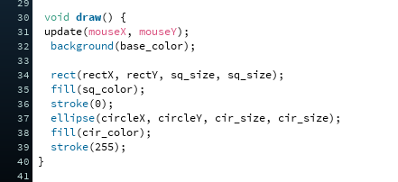
This is the part where the actual draw of the forms would happen
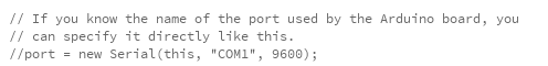
PORT
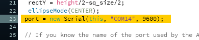
Here you select the port for the signal, example: “COM 14”
9 600 is how fast the information transmition will work.
hello out in.brd
bancamaqueta.ai
BOTONESCHACHA.pde