For this week, we had to design and build a wired/Wireless network that connects at least 2 processors.
For that I decided to modify the serial bus network.
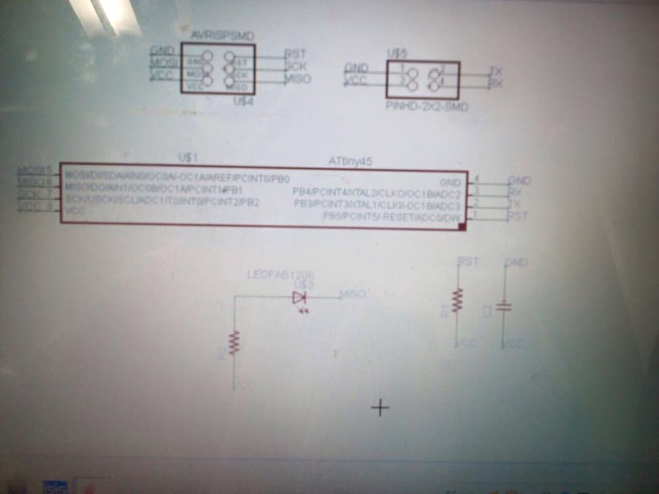
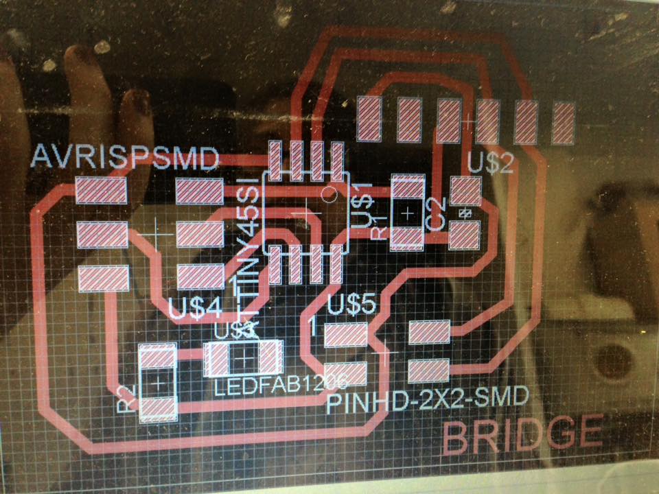
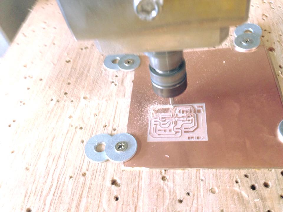
As usual, I went to Eagle to do the schematics and the boards. Then I went to the Flat Cam before milling them on the Modela MDX 540 and finally did the soldering.
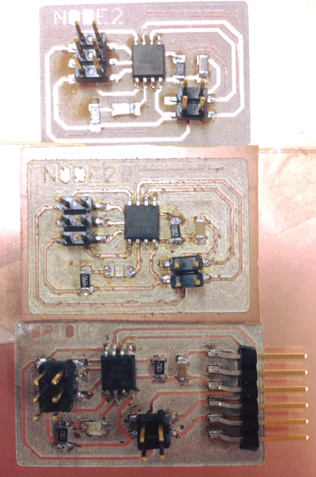
I did three boards:
1. Bridge:
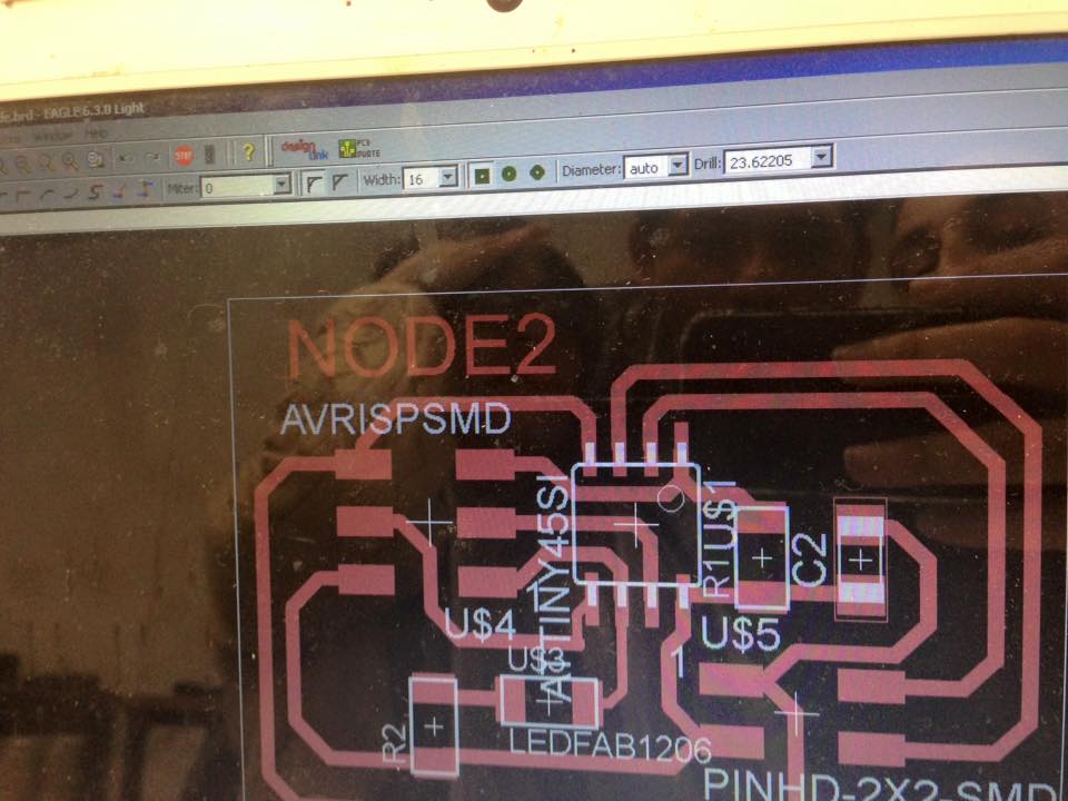
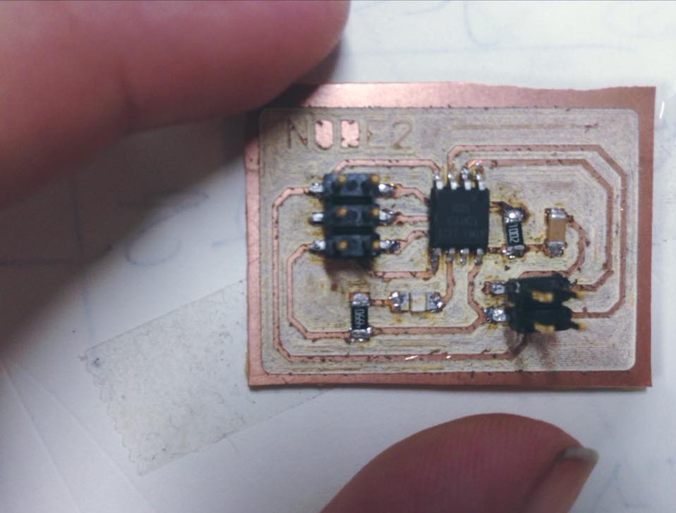
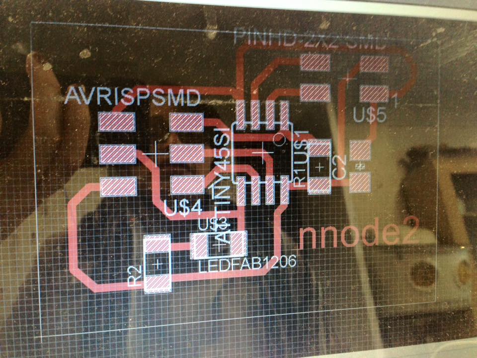
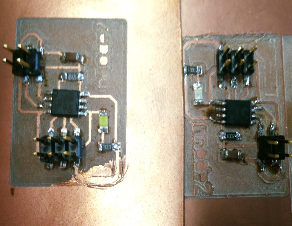
2. Node (two boards):
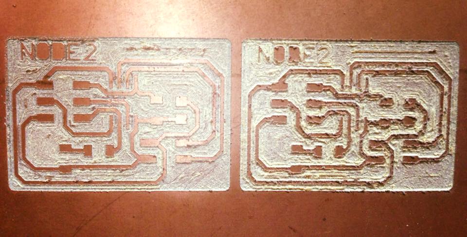
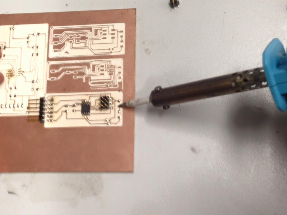
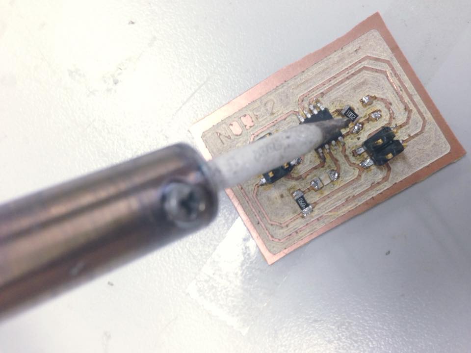
After the milling, I continued with the soldering:
With help from the FABISP from the electronics Production software the programming can be made.
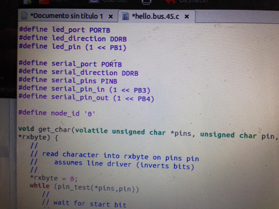
The .C file is here:
http://academy.cba.mit.edu/classes/networking_communications/bus/hello.bus.45.c
The Make file is here:
http://academy.cba.mit.edu/classes/networking_communications/bus/hello.bus.45.make
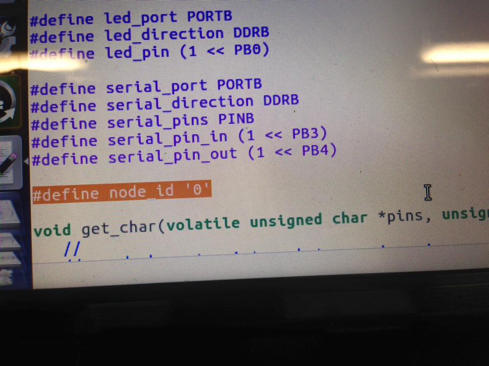
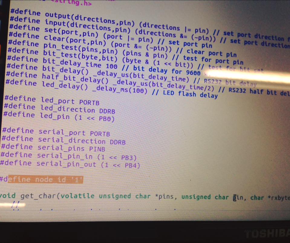
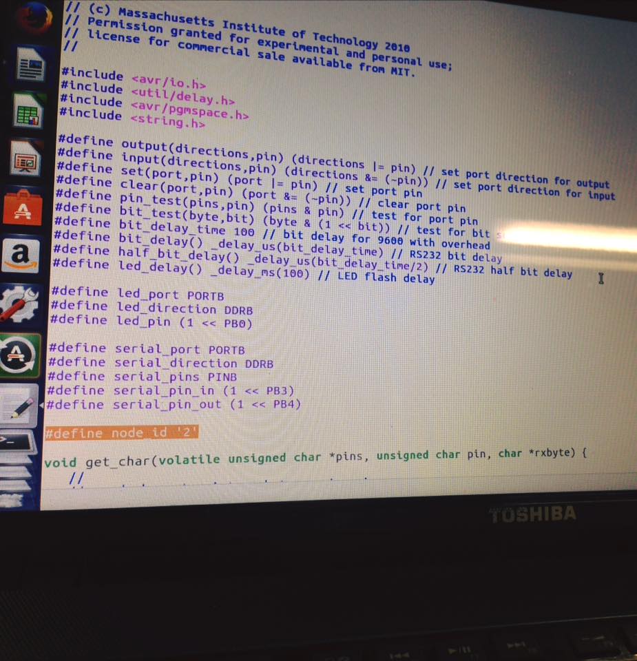
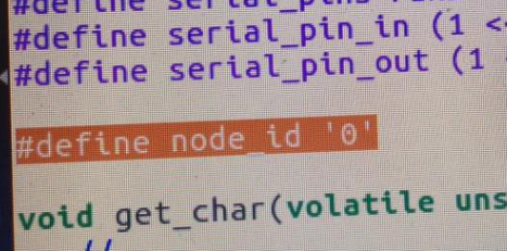
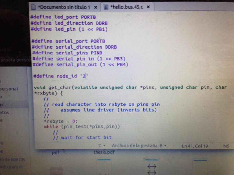
But before the actual programming, a line of the code must be changed.
Each board must be conected to the Fab ISP which must be cnected to a usb port.
Then type:
Sudo make- f hello.bus.45.make program-usbtiny

This step must be made with all the boards (bridge+node+node)
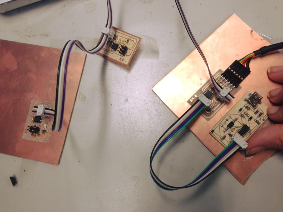
After all the programs are loaded, the boards must be connected, for that, as done in other assignments, connect the FABISP to a USB port of the laptop.
Then, the pinheads from the bridge board must be connected to an FTDI cable, and then to other PC port.
With all that under control, the bus communicator wire must be connected to all the boards (bridge+node+node)
Arduino is useful to test everything is working. For that, the serial port must be open.
When writting the commands 1 or 2. The each node (1 or 2) must blink.
In my experience Arduino IDE is my go to place for this kinds of Jobs, but if searching for other options, Python can be use as well. The term.py file:
http://www.kaziunas.com/downloads/fab/term.py
Can be downloaded to run the program from the Python term.py/dev/ ttyusb0 9600
Serial_bus_bridge.brd
Serial_bus_bridge.sch
Serial_bus_node.brd
Serial_bus_node.sch
I had a problem making the boards work properly, so I checked different aspects as the soldering, continuity in the boards and finally I went to the At tinny datasheet, wich is here:
http://www.atmel.com/Images/Atmel-2586-AVR-8-bit-Microcontroller-ATtiny25-ATtiny45-ATtiny85_Datasheet-Summary.pdfThere I found my mistake, as you can see in the second page the number five goes to PB0 is MOSI and number 6 PB1 is the MISO.
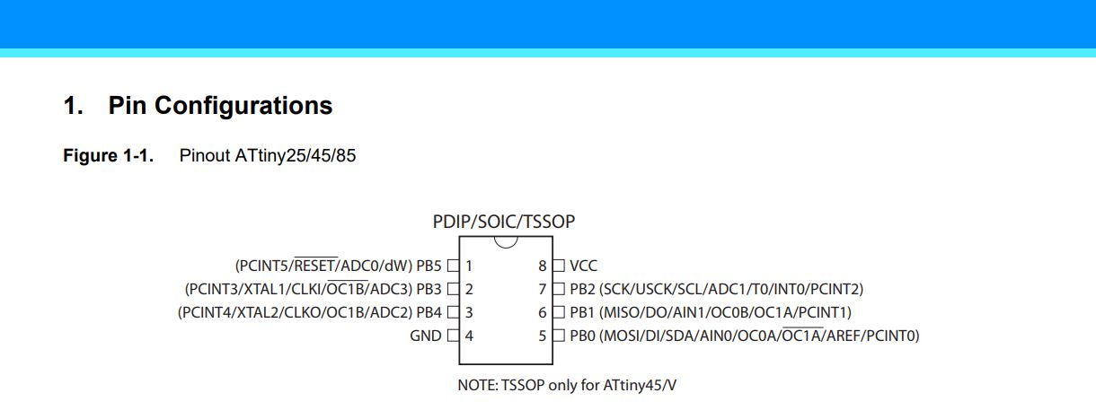
So I had to start over and make the boards again.
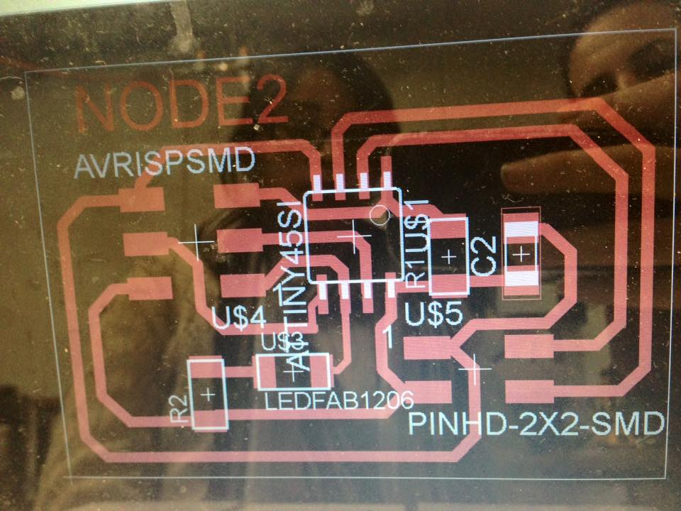
Here are the new boards for the bridge and nodes
(new files at the end)
Then as ussual, milling on the modela and soldering.
Then, every board must be loaded with the: hello.bus.45.c.
Changing the node 0, for : 0, 1 and 2 (every board must have the
Same code charged, with that difference)
For this each board must be conected to the FAB ISP and to the UBUNTU terminal.
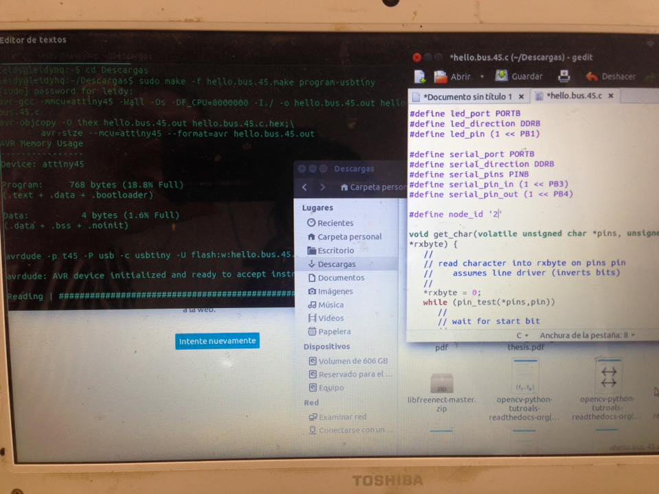
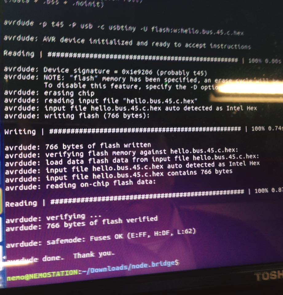
This means the loaded have worked:
leidy@leidyhq:~/Descargas$ sudo make -f hello.bus.45.make program-usbtiny
avr-objcopy -O ihex hello.bus.45.out hello.bus.45.c.hex;\
avr-size --mcu=attiny45 --format=avr hello.bus.45.out
AVR Memory Usage
----------------
Device: attiny45
Program: 768 bytes (18.8% Full)
(.text + .data + .bootloader)
Data: 4 bytes (1.6% Full)
(.data + .bss + .noinit)
avrdude -p t45 -P usb -c usbtiny -U flash:w:hello.bus.45.c.hex
avrdude: AVR device initialized and ready to accept instructions
Reading | ################################################## | 100% 0.00s
avrdude: Device signature = 0x1e9206
avrdude: NOTE: "flash" memory has been specified, an erase cycle will be performed
To disable this feature, specify the -D option.
avrdude: erasing chip
avrdude: reading input file "hello.bus.45.c.hex"
avrdude: input file hello.bus.45.c.hex auto detected as Intel Hex
avrdude: writing flash (768 bytes):
Writing | ################################################## | 100% 0.76s
avrdude: 768 bytes of flash written
avrdude: verifying flash memory against hello.bus.45.c.hex:
avrdude: load data flash data from input file hello.bus.45.c.hex:
avrdude: input file hello.bus.45.c.hex auto detected as Intel Hex
avrdude: input file hello.bus.45.c.hex contains 768 bytes
avrdude: reading on-chip flash data:
Reading | ################################################## | 100% 1.18s
avrdude: verifying ...
avrdude: 768 bytes of flash verified
avrdude: safemode: Fuses OK (H:FF, E:DF, L:62)
The final video showing the network working is here:
nodeb.brd
nodeb.sch
Serial_bus_bridgeb.brd
Serial_bus_bridgeb.sch