OBJECTIVES
Add an output device to a microcontroller board and program it to do something.
Add an output device to a microcontroller board and program it to do something.
For this week assignment I used the Satsha Kit, here is the original link with all the information: https://github.com/satshas/satshakit
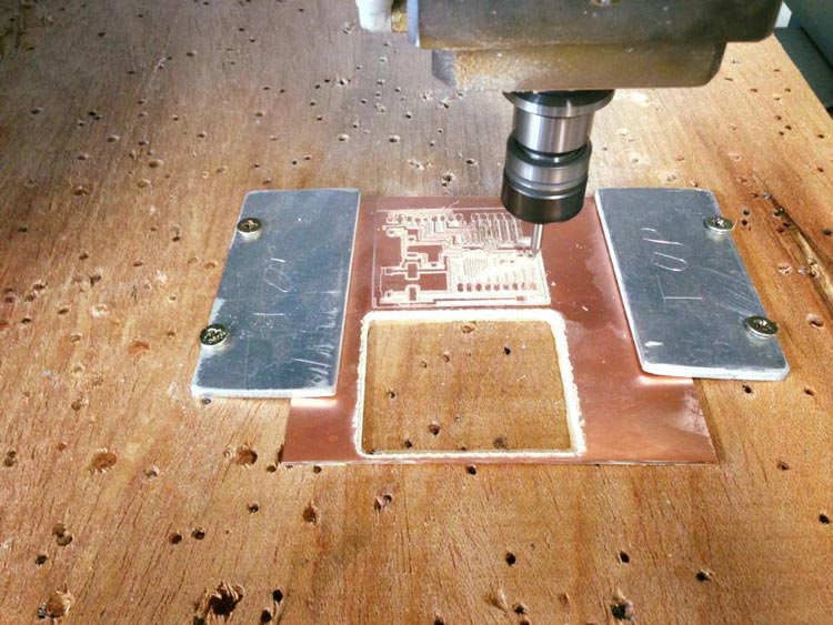
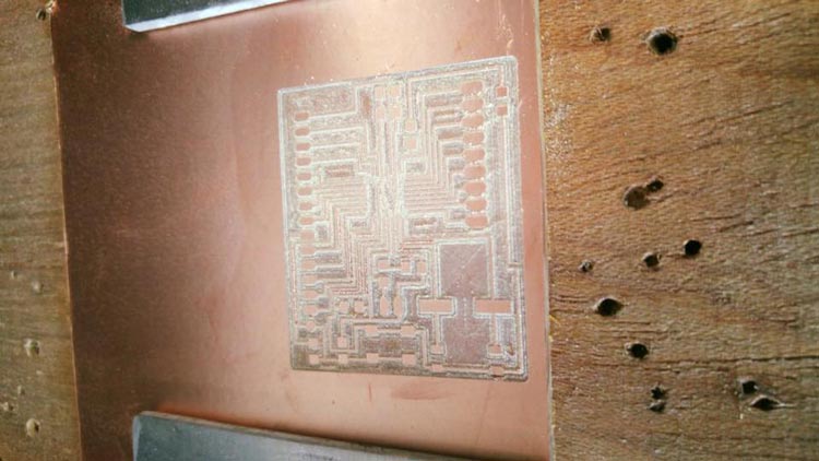
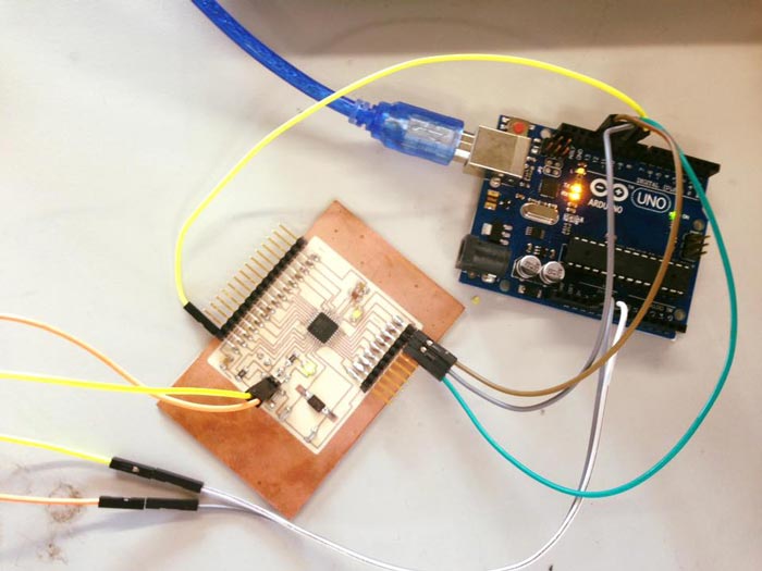
With the design set, the process of milling it in the Modela machine started. We have been having some problems milling, because the boards weren´t even and in some places the job wasn´t done, but Guillermo put two metal pieces holding the board so the board itself dosen´t need to be drilled. This helped the process.
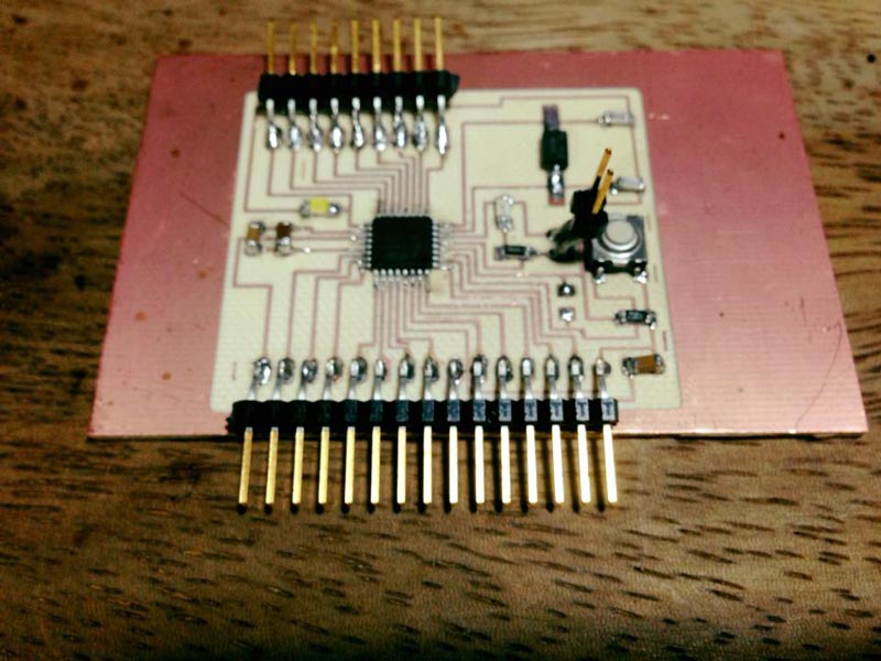
Then was the welding process, the ATMEGA 328 was especially challenging, but with lots of patience I could finish it.
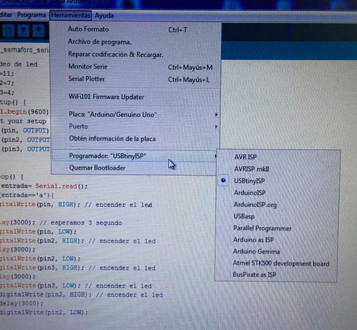
For the programing part I used an Arduino One on the first tries it didn´t work.
I had to check all the welding over and over again.
I checked the continuity and it worked ok, but when trying to burn the bootloader.
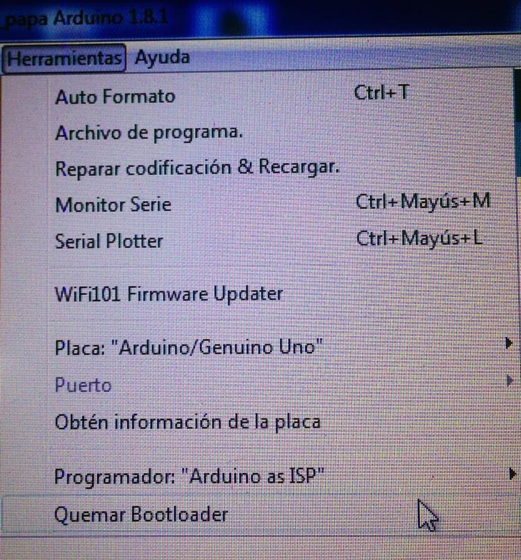
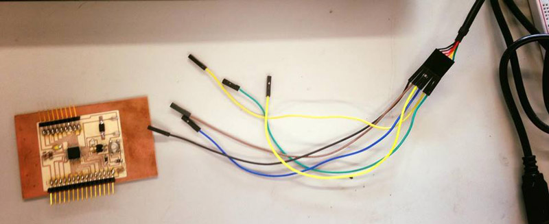
Then I tried changing the Arduino one for the Fab ISP to burn the bootloader, again mistake.
Then I tried it in a computer with Linux and it worked. Turns out one of the problems was the port of my computer wich didn´t recognize the ISP.
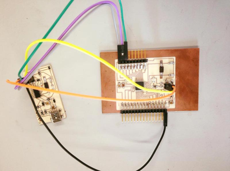
Then, as instructed on the Satsha kit web it connected my board to a FTDI USB cable Where a programmer is no longer needed.
After programming the Satsha Kit to work as an Arduino, the assignment asks for creating an output device.
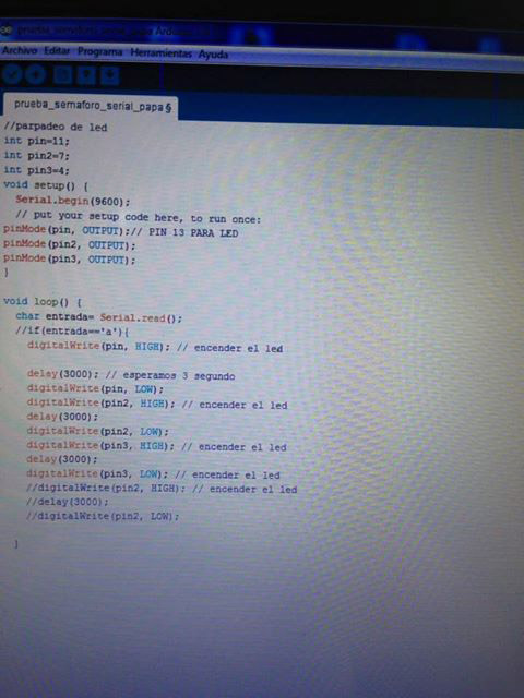
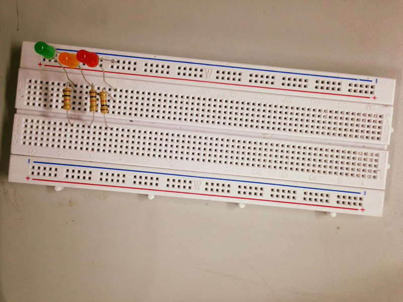
So for this, I did a traffic light excercise. Programming it in the Arduino software and using a protoboard first to test the idea.
The Arduino code is:
And the protoboard with the looked like this:
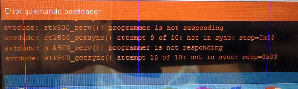
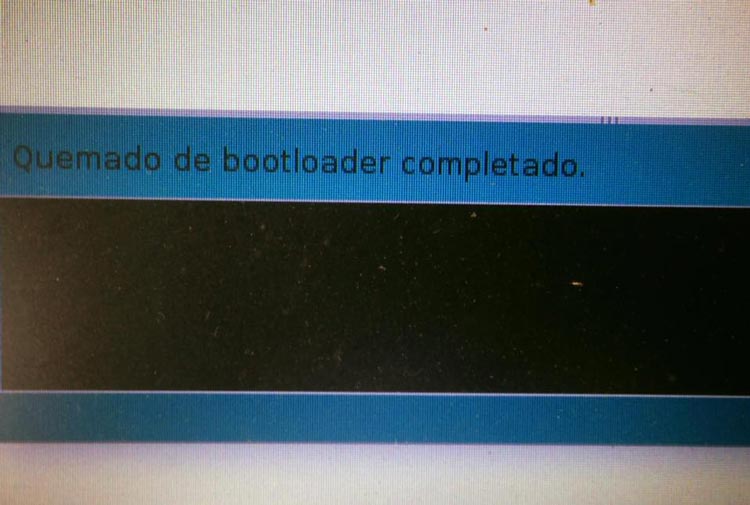
But even after successfully burning the bootloader, when trying to upload the Arduino code there is an error. After many tries the same error appears:
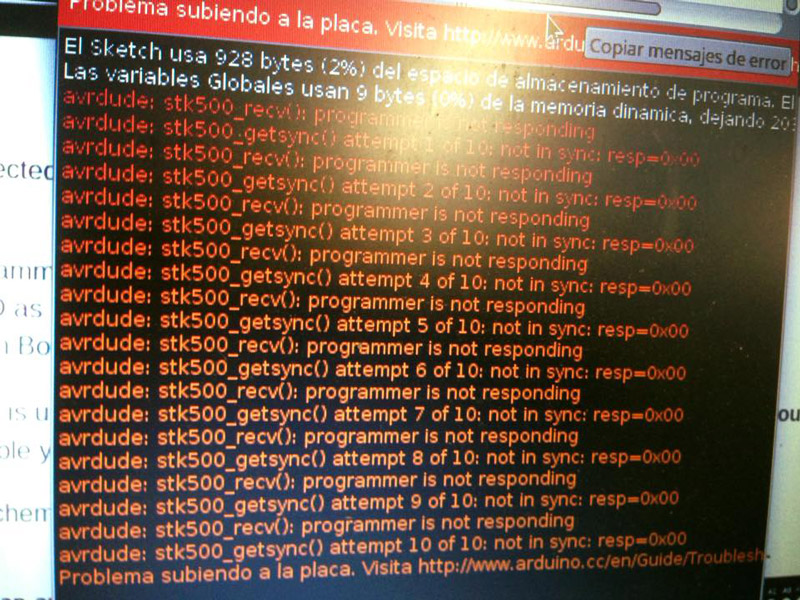
It says the the programmer is not responding. I´ve checked everything I can think of, all the welding, the directions of the components, the FTDI cables, continuity, even tried with different Arduino versions. But the same appears. Also asked for help to my mentor and other students in the lab and assistans, but still no clue why. We have asked to the lat gurus to see if they understand what´s going on.
At the end I review again all the components and the path and tried againg and it worked.
I decided to focus on the final Project and changed the traffic light exersice.
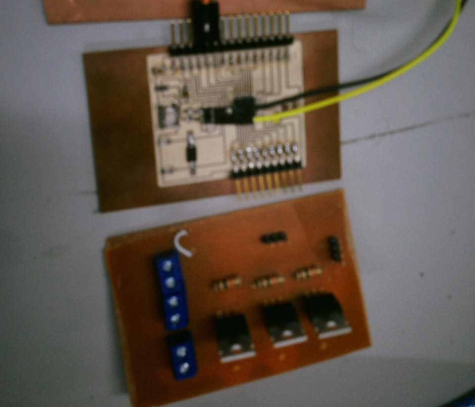
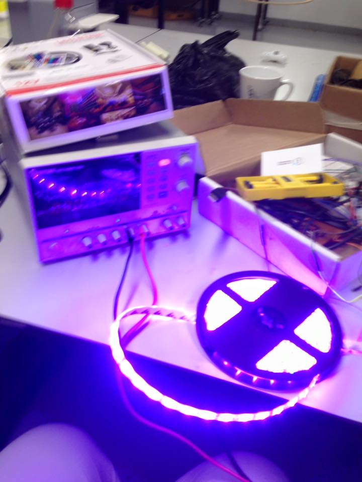
For my final Project I need a board that can work with the satsha to control a
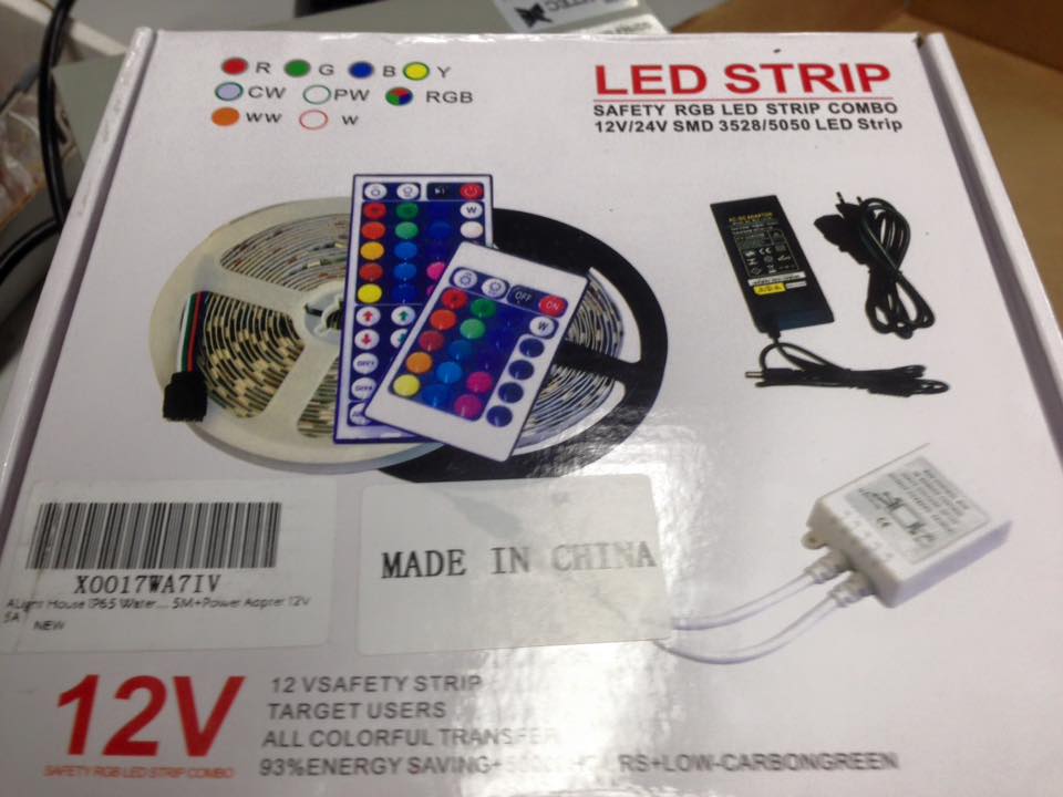
RGB LED STRIP. As an Input, later I would use a board with piezo electrics so when each of them activate, the signal would change the light colors.
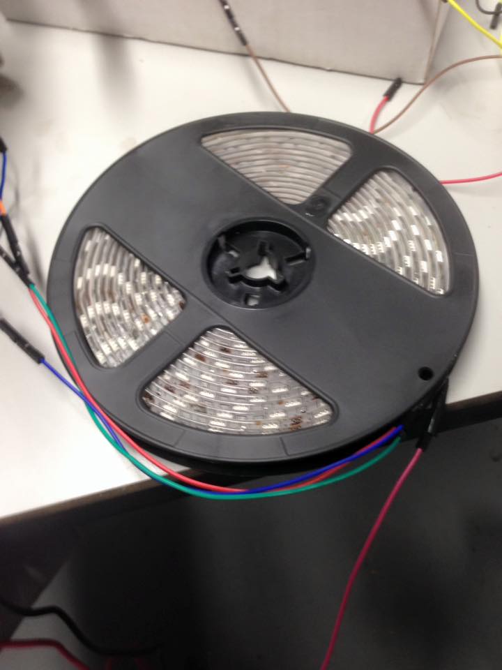
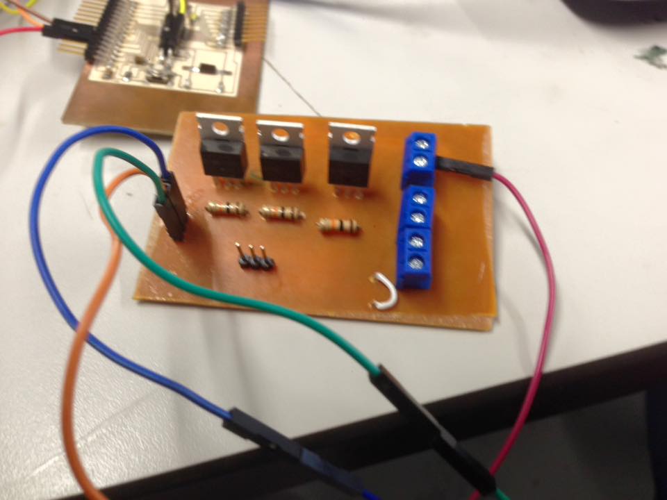
The RGB Led Strip is 5 meters long and uses a 12v battery.
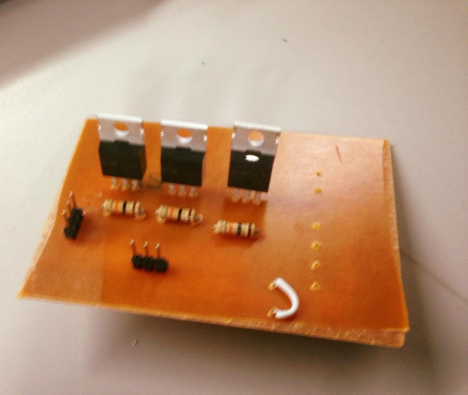
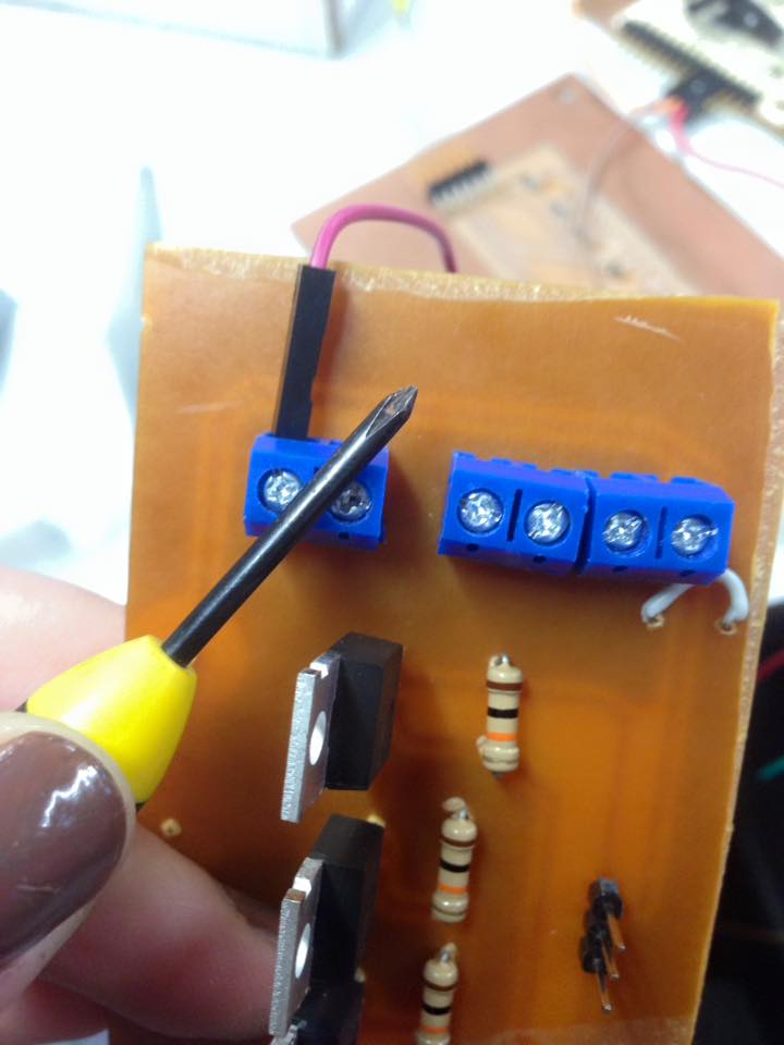
For this I needed IRFZ44N Mosfets but i couldn´t find them on MSD on the lab or the local market, so i bought the through hole versión. I´ve never used that technique so it would be a good pretex to learn.
For this board I needed:
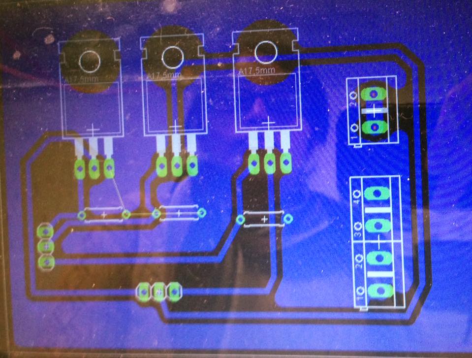
As usual I did the board on Eagle:
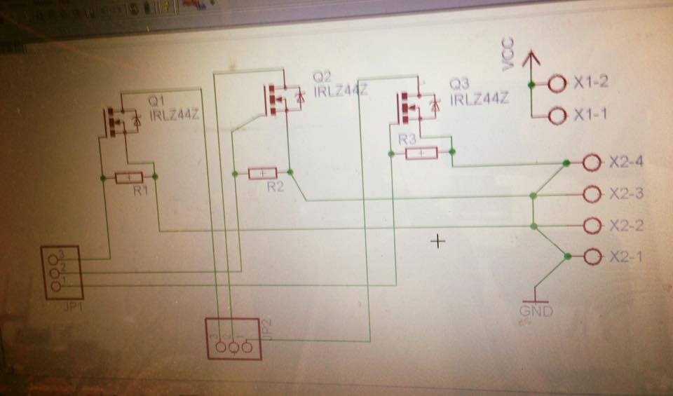
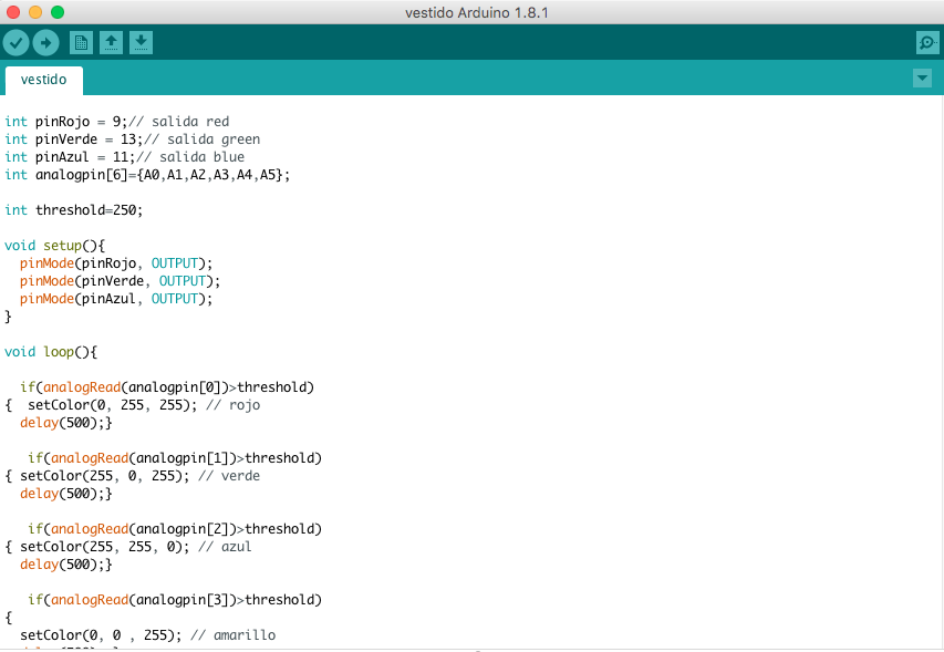
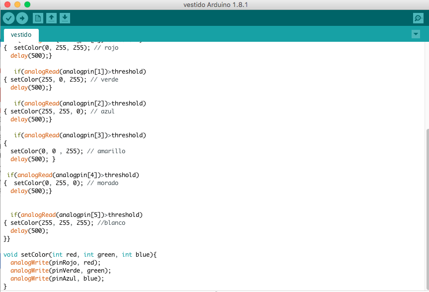
I used the arduino to program the secuence of the lights colors. Here is the file
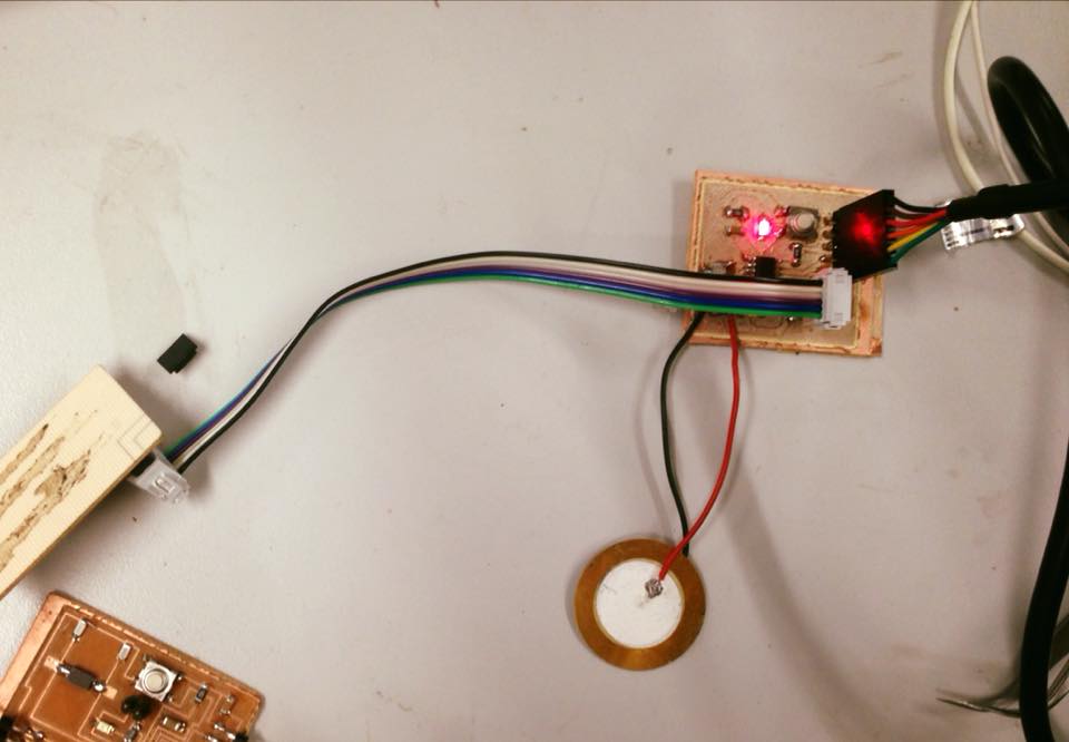
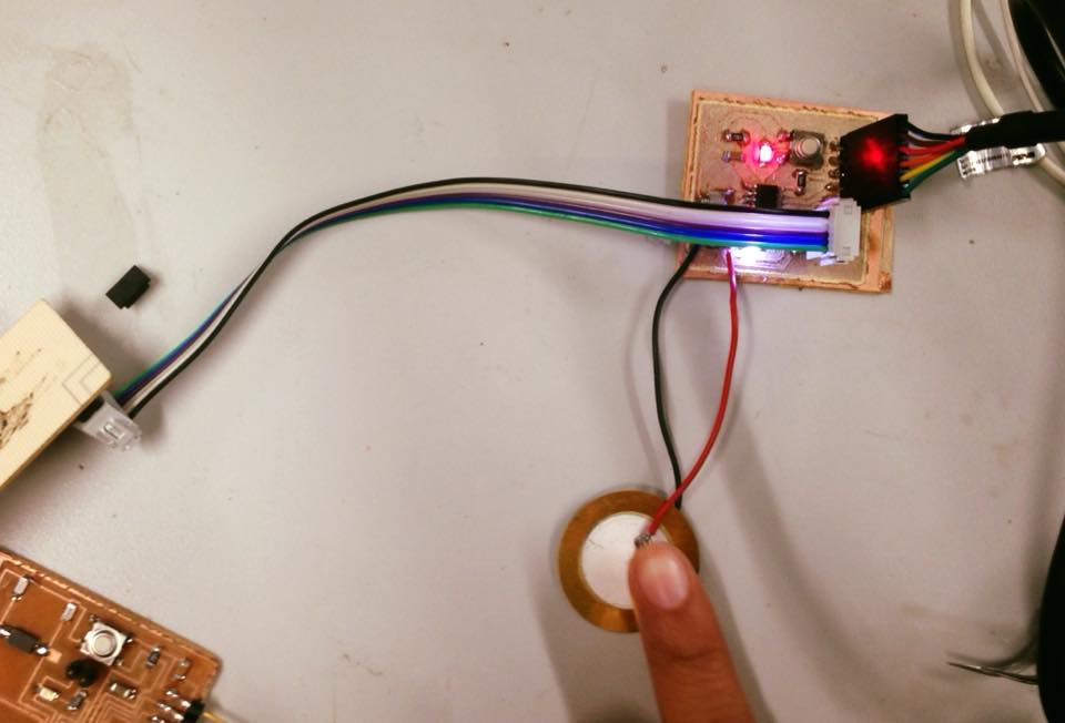
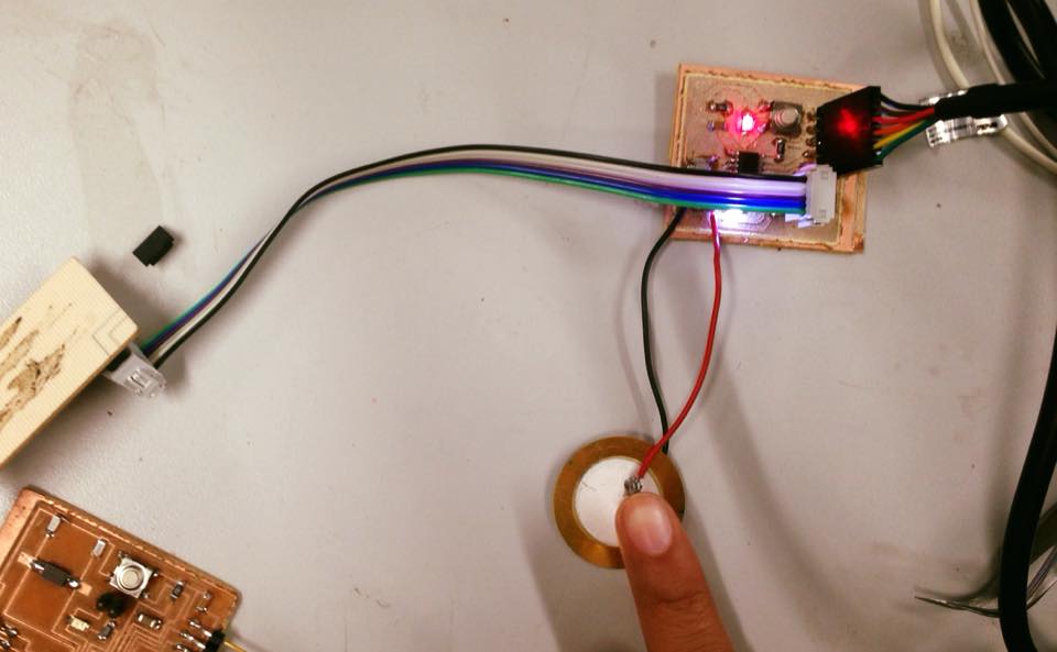
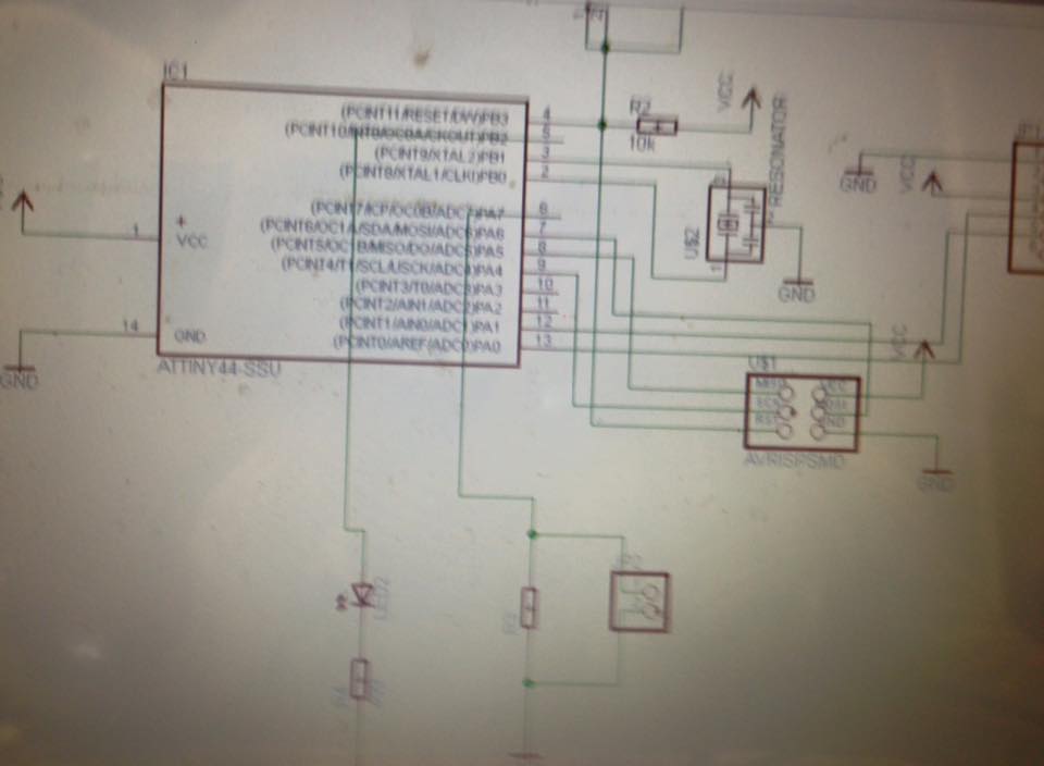
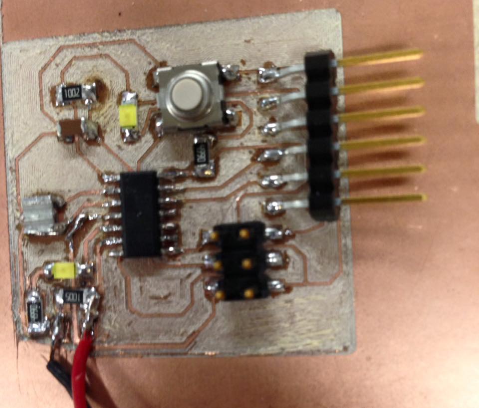
Then I decided to make a board with an Out put that has it´s own microcontroler, In this case, I modified a Hello board.
This new HelloBoard has both out put , in form of led lights and Input, a piezo electric.
And works with a AT Tiny 44.
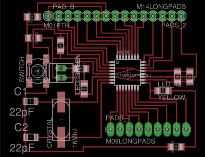
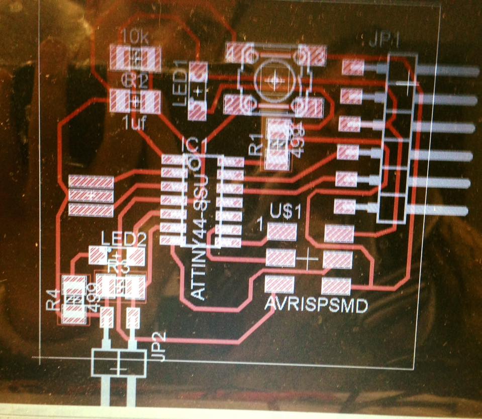
As usual, the first step is on Eagle.
Schematic:
Board:
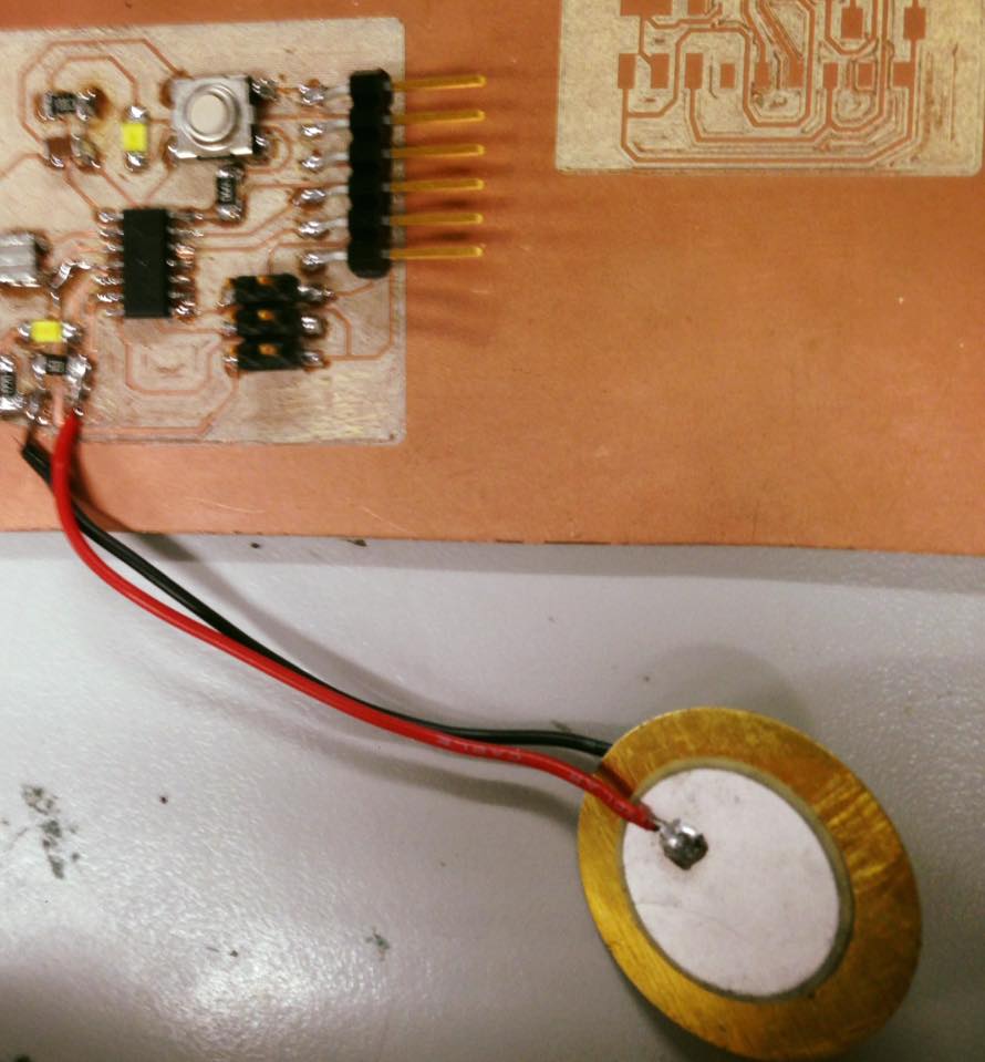
After soldering, it looked like this:
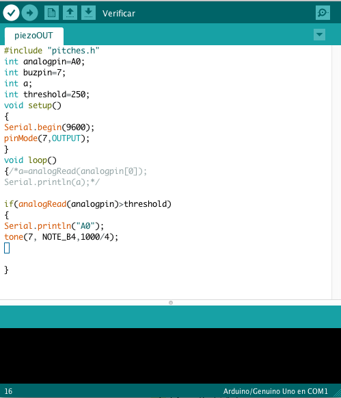
Then I did the Arduino code:
Then, upload the program:
And finally, It worked like this: When the PIEZOELECTRIC (INPUT) is touch, the LED LIGHT (OUTPUT) turns on.
As seen in this pictures: