Electronics design
This week assignment is to redraw the echo hello-world board and add at least LED and push button .
software I will use :
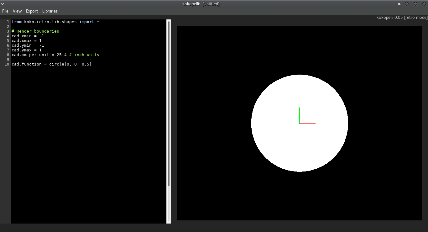
For redrawing the echo hello-world board I will use kokopelli software.
This is the first time to use this software for downloading this software I went to kokoretro and cloning it.
before start installing kokopelli there are some softwares need to be downloaded
Needed softwares
- Python
- wxpython
- Numpy
- Gcc and G++
- libpng
- GIFLIB
- Make
- BASH
- OKULAR
- Boost
- cmake
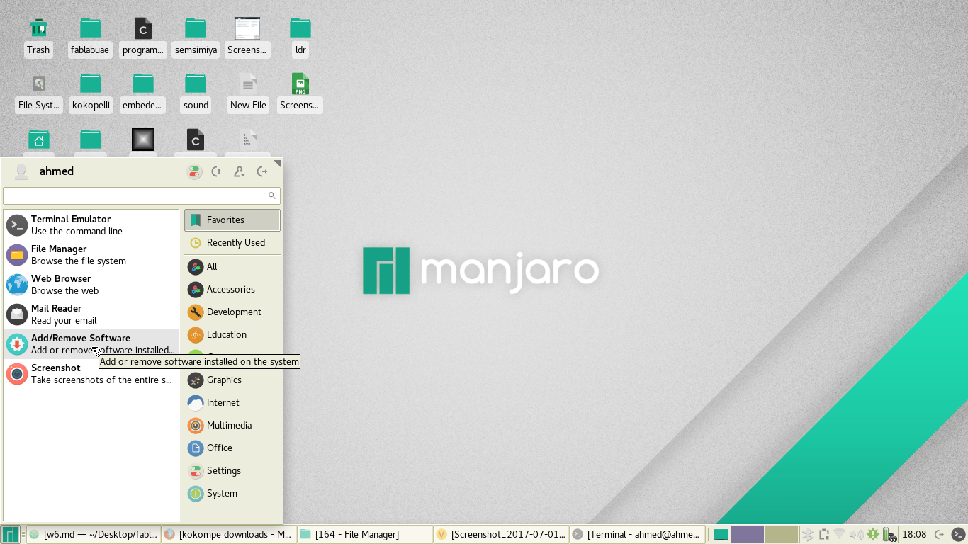
As I use linux manjaro I download all this softwares from Add\remove software as in the following image
Compiling the software
- To compile, after downloading the source above, unzip fab_src.zip and cd to the folder it's in.
- I write make fab, which should compile all executable and copy scripts into bin.
- At this point, make install will copy all executable and scripts to /usr/local/bin.
- Now I have folder of kokopelli that have the software and ready for use.
- For opening the software I go to bin folder inside kokopelli folder and open the terminal and write this command python2 ./kokopelli -r
Machine for milling the board:
For milling the machine I will use Roland Mono fab machine
Now I have every thing (tools,machine and software) for start making my board.
Steps for editing the hello-world board:
After having the software it is time to edit the echo hello-world board.
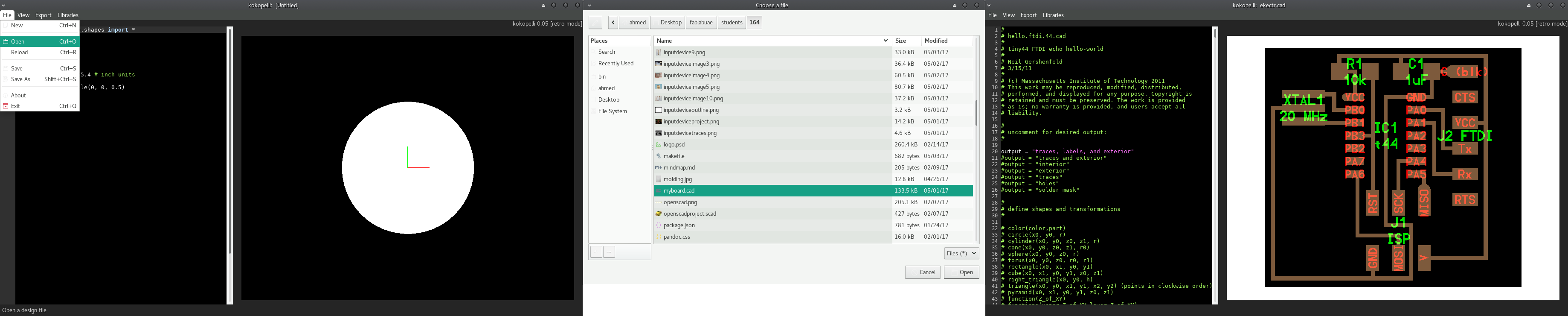
The next step is to obtain the cad file : - At first I go to fab academy repository and open file called hello.ftdi.44.cad.
- Make a copy of the file.
- Make new text file and past on it.
- I save the file myboard.cad so I can open it with kokopelli.
Here the orginal file of echo hello-world board
orginal file
After obtaining the cad file I will open it with kokopelli.
For opening kokopelli software : - I go to the folder of kokopelli.
- then go to folder called bin.
- And I open the terminal.
- Last thing is to write this command python2 ./kokopelli -r.
Then I will open the file of echo hello-world board
Now this is the time for making changes on the board and what I will do is to add LED and push button now I should know the dimension of the LED and push button and the resistors to make the bads.
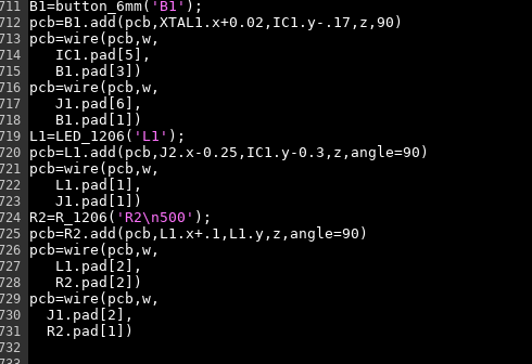
At first I make search I found that in the code we have classes of the push button , resistor and the LED so what I do is I will call this class.
This is an example for calling the class of LED
L1=LED_1206('L1');
pcb=L1.add(pcb,J2.x-0.25,IC1.y-0.3,z,angle=90)
- L1 is the name I choose for the LED and should not be repeated in the whole of the board.
- LED_1206 is the name of the class of the LED
- pcb=L1.add(pcb,J2.x-0.25,IC1.y-0.3,z,angle=90) this is the place where I want to put the LED, I should put it related to component or to the coordinates x and y and also the angle you want the component to be horizontal or vertical.
After adding the component I should wire this component to another components.
This is the code for wiring the LED to PA5 in IC1 and to the resistor.
pcb=wire(pcb,w,
   L1.pad[1],
   IC1.pad[8])

pcb=wire(pcb,w,
   L1.pad[2],
   R2.pad[2])
This is to wire from pin1 in L1 to IC1 pad 8 and the second is to make wire between pin2 in L1 to pin2 in R2.
Now I have connect the LED to attiny and to the resistor.
with the same way I add the resistor and push button and wire them.
One of the problem I have is that I cant make wire to component before I add it so at first I add all component I need then I start wiring them so I can not have problems.
#### Problem I faced when I used kokopelli
As this is the first time I use kokopelli so our instructor Francisco taught us the principles of using kokopelli for making circuit board.
The first problem that when I wrote the code in kokopelli I had many of errors as I didn't know that the software start compiling from from above to below so if I use any function in the line above the line I defined it the program give errors.
Second problem is to know the minimum space between the traces that can be milled so for solving this problem I should know the working area of the milling bit.
#### How to calculate the needed current limiting resistor
For calculating the current limiting resistor of the LED I use this website in this website I put the supply voltage and voltage drop across the LED and the desired LED current and the website calculate the exact resistor.
The voltage drop across the LED and the LED current I find it in the data sheet of the LED.
SO the needed resistor from the calculation is 300 ohm but we don't have in the lab so I will use 500 ohm but the light will not be full strength but its ok.
This image show how I add the push button,LED and resistor.and also show the place of each component in the board.
Here is the image of the board after editing 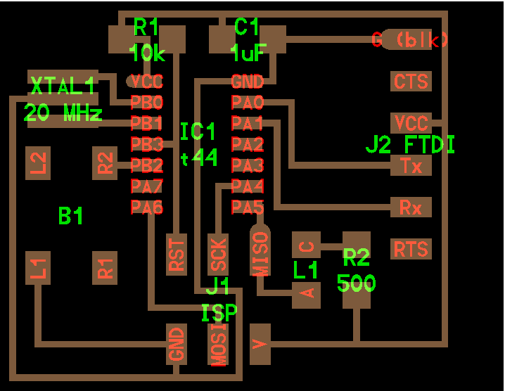 So now from this file I should have PNG files for the traces and outline.
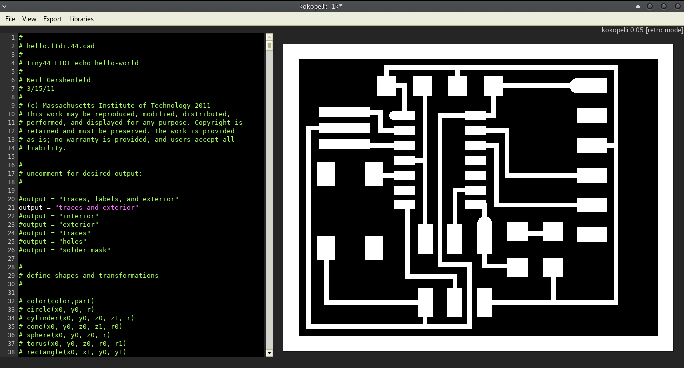
For obtaining the traces of the board. In line 21 I find that traces and exterior was made as comment so I remove the comment tag from it.
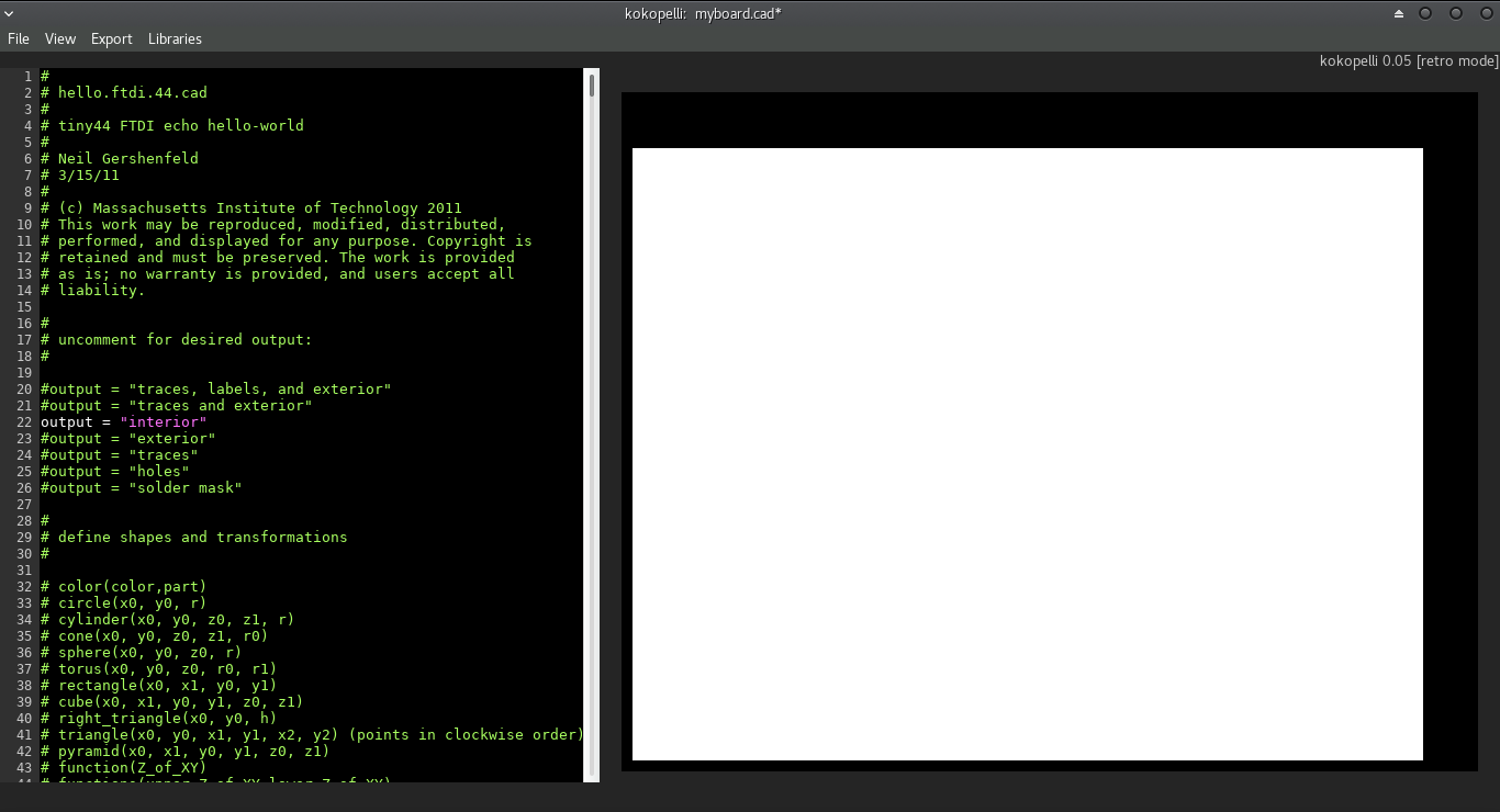
In line 22 I will do the same step to obtain the outline
This is the time to export the traces and outline of the board, but the resolution of the image should be 25 pixel
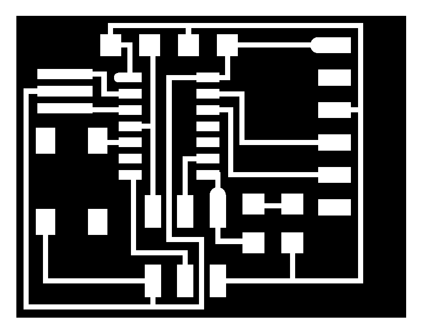
At the end I obtain the PNG files of the traces and outline.
PNG of the traces :
PNG of outline:

Milling the board :
After finish editing the board and have the PNG files of traces and outline I should convert them to RML file.
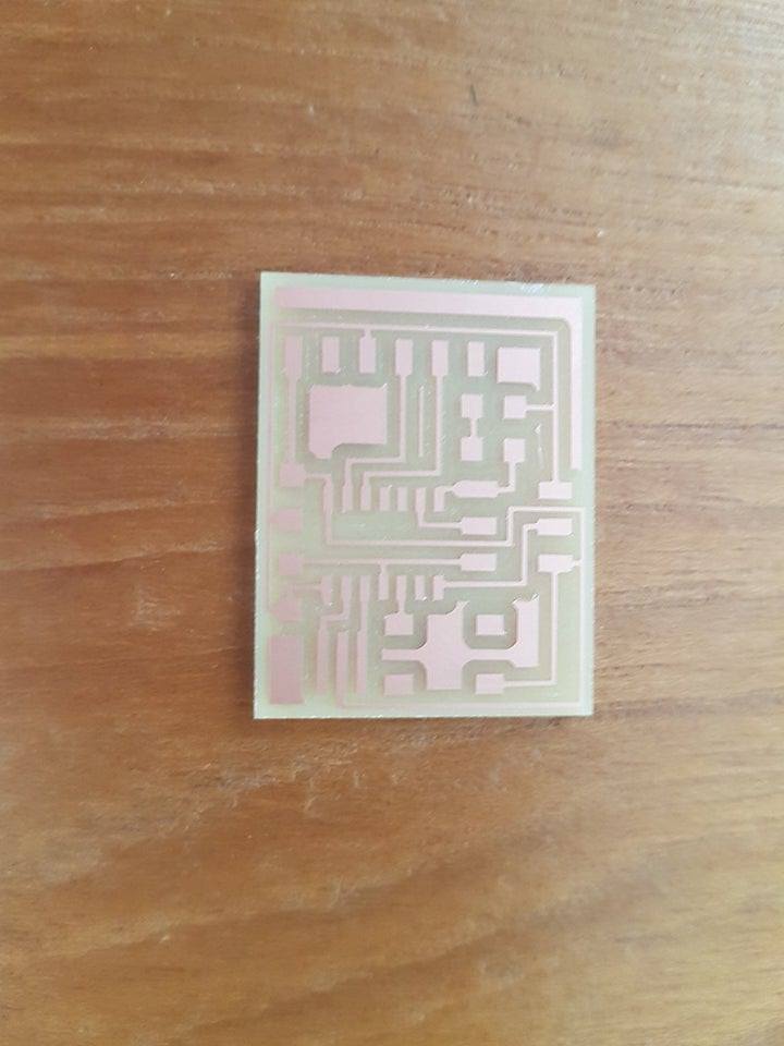
Similar to week4 Electronics production assignment I will use fabmodules website to convert the PNG files to rml files with the same way I use in week4. Now I will send the RML files to CNC monofab and start milling the board. Here is the board after milling finished
Soldering the board
By using soldering skills I learned on week4 I will solder the board, after the soldering I make test to find any short or open lines on the board but from my lucky that the board is ok and have no issues.
final cad file