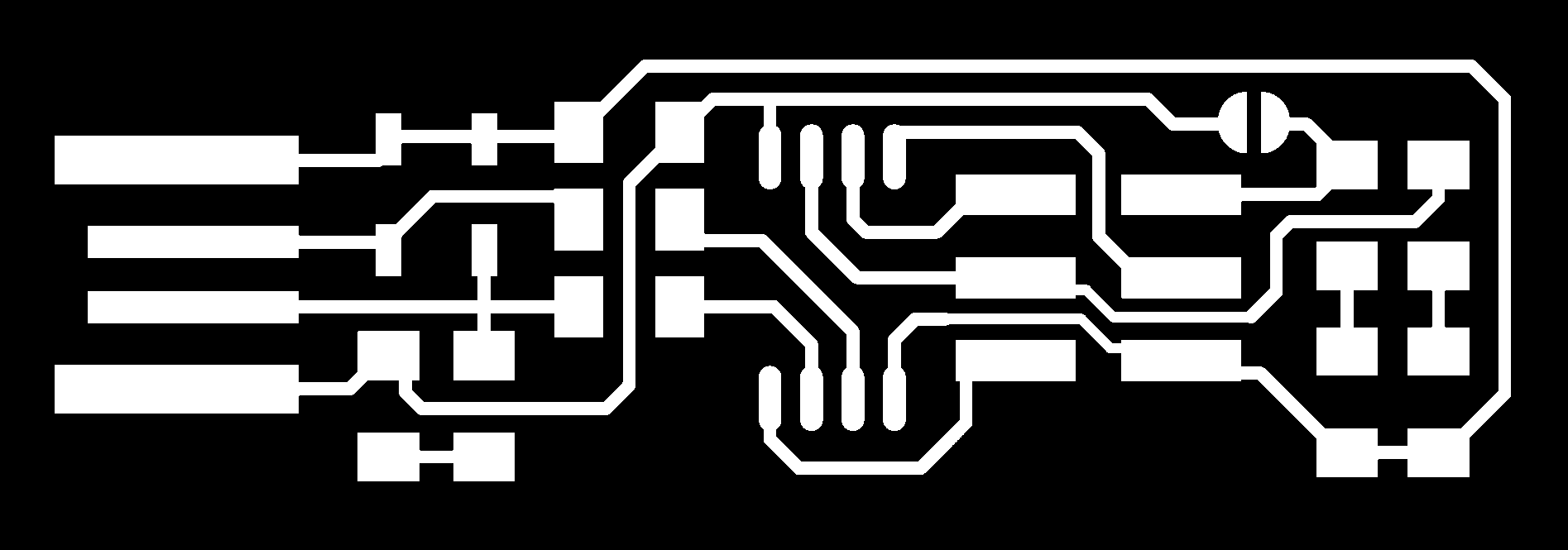
I download the PNG file for traces.
Also download the PNG file for the outline

The goal of this week Assignment is to make a circuit board programmer by milling the pcb and programming it to use it as a programmer that I can use it to program my Electronic boards in the next electronic weeks.
First I chose Brian board to make my fab ISP.
I download the PNG file for traces.
Also download the PNG file for the outline
By using fab modules website I will convert PNGs files to RML files. Here is the video that show how to convert PNG files to RMl file.
Now I have the RMl files for the traces and outline of my board.
The next step is milling the board using CNC . The machine we have in our lab is mono fab CNC machine that I will use it to milling the board.
So I will use a software called vpanel for SRM-20
After having the rml files for the traces and outline I will use milling bit 1\64 inch to mill the traces of the board and milling bit 1\32 to mill the outline of the board.
First step I do is I attach the milling bit in the Colette and thigh it and make the milling bit is 3mm far from the surface of the board.
The next step is that I move x and y axis to the place I want to start milling and zeroing x and y.
Now after zeroing x and y it is the time to zeroing z.
For zeroing z I will un tight the milling bit and let the bit go down till it reach the surface of the pcb. and start running the spindle the speed of the spindle is 9000 and moving the z axis slowly until it go very little inside the pcb, when it go down I stop the spindle and make this coordinate as the zero of z.
Now I have zeroing x,y and z and the machine ready for working.
To start milling the traces I press on cut button and choose the rml file of the traces and press output so the machine start milling the traces.
After machine finish I will press on the button of preview mode and clean the board using vacuum cleaner.
For milling the outline outline at first I will remove the milling bit of the traces and but the milling bit of outline with the same way.
For choosing the origin place of x and y I will choose user coordinates system and press x/y to origin to move the two coordinates to the zero point and with the same way I make the origin of z in traces milling I will make it in outline.
After all axis are in the zero I will cut the outline with the same way I cut the traces.
After the machine finish I will choose the preview mode to bring the plate out and cleaning it using vacuum cleaner.
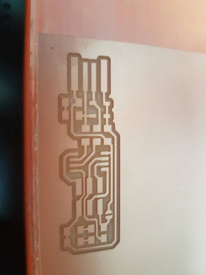

After I finish milling the board now the board is ready for soldering the Electronic components.
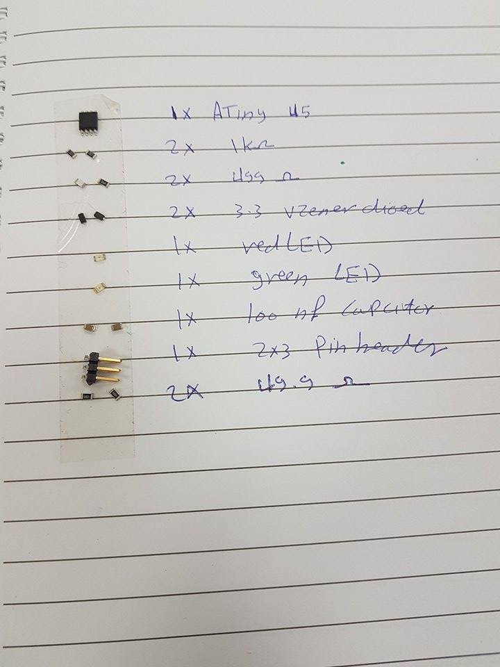
This is the Electronic components I will use in my board.
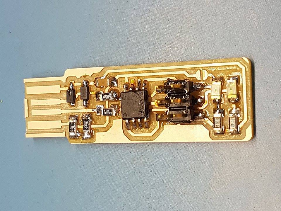
Now This is the time for soldering.

After finish the soldering I obtain the final board.
 Now the board is ready for programming.
First I should make improve To the USP connector so i can use it without problems. so I should remove the copper part in front of the board.

Now after I finish the soldering and make the improve of the usb the red LED should work when I connect my board to computer. The board should connect to USP ver2
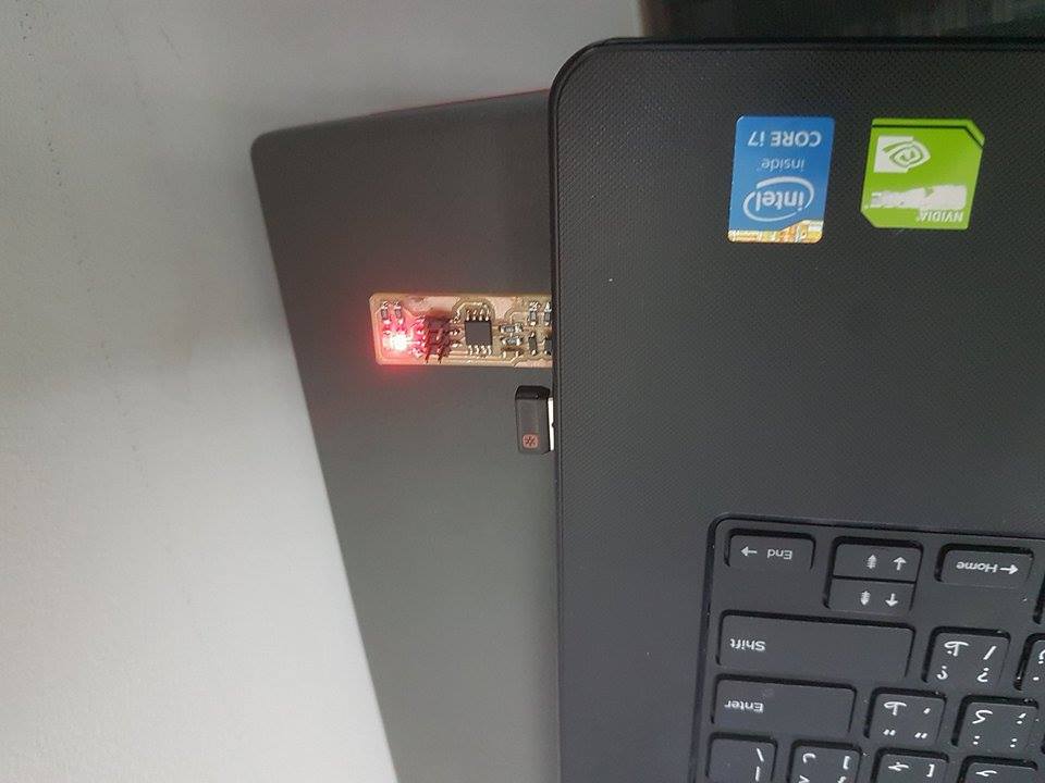
Now I am sure that there is no problems in soldering and the board is working.
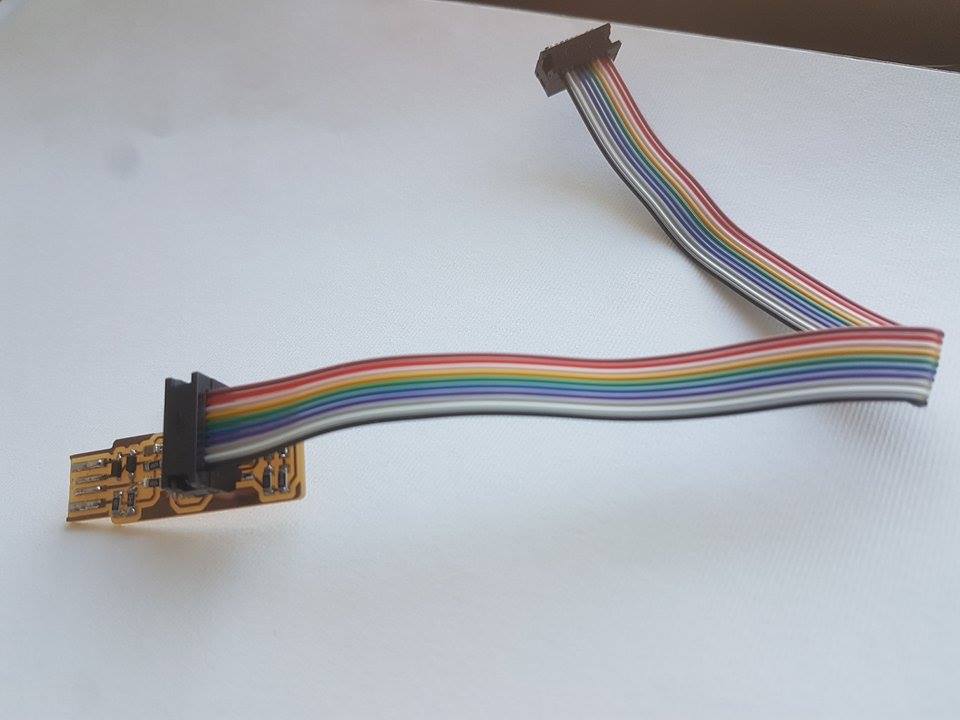
For programming my board and use it as programmer in the future I should make connector cable.
The cable I make is 10 pin connector and what I need is 6 pin connector but in this time we only have 10 pin connector on the lab so I will make it using 10 pin connector and use it as 6 pin connector.
The way of making 10 pin connector to work as 6 pin connector is that is that I will put the cable in the first 6 pin and the 4 rest will be useless so I can use it as 6 pin connector.
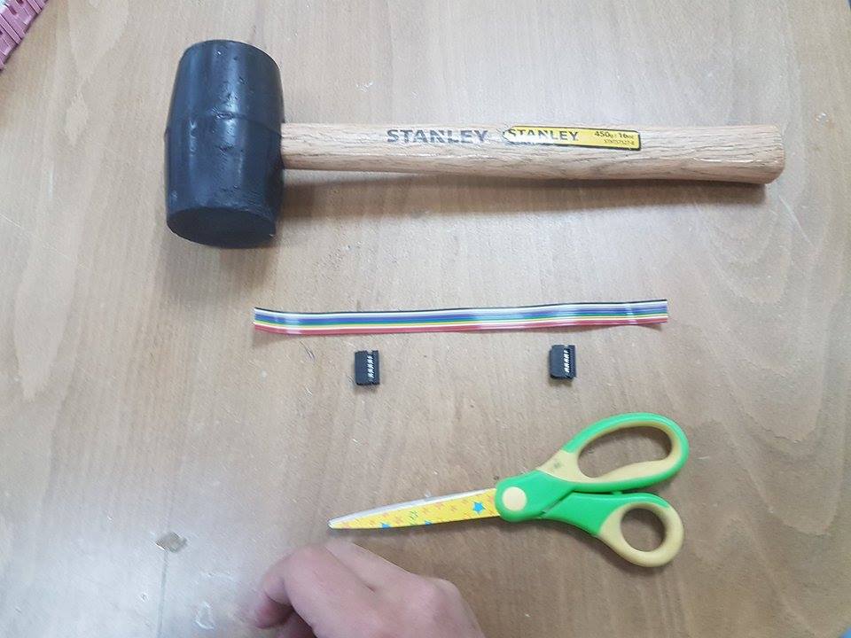
Here is the tools I will use to make my cable
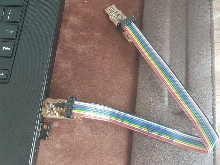
This is the final image of the programmer with the connector.
The final step is to programming the board.
As I use linux manjaro I should download all software needed like avrdude gcc-avr avr-libc
From the page of the board I can download firm-ware source code.
The link of the page
Now I connect Francisco fab ISP programmer Andy programmer to my computer and connect it to my programmer using the cable I made before.
For making proper connection between Francisco fab ISP and my fab ISP programmer I put the two ISP in the same direction to know the arrange of the pins in the two boards and start connect the cable between them so the connection will be proper.
This image of the two board 
This image show that Francisco board connected to computer and connected to my ISP programmer using the cable.
After downloading the firm-ware and unzip it I will have two files the make file and fts-firmware.elf.
First I modify the make file to change the programmer to Attiny 44.
The next step is that i go to the folder that contain the firm-ware files and open the terminal and write command make flash this command to erase target chip and and program its flash content with .hex file, next command is make fuse set up all of the fuses except the one that disables the reset pin.
List of the commands
- sudo make flash
- sudo make fuses
- sudo make rstdisbl
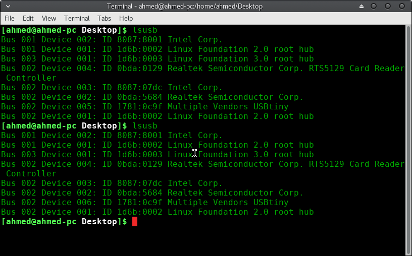
As I mention in the problems that the fab ISP sometimes working and sometimes not working so I plug it into usb many times till it working and this image show that the computer recognize the fab ISP.
This video show that the computer recognize my fab ISP and I use it to program the board to make blinking
The problem I have is that the board at first not working I review all commands I write in the command line but its ok so I start debugging in the soldering as Neil said in week4 lecture that the soldering should be shiny so I start soldering again the component I see it is not shiny and the board work.
During fab academy course I find that the ISP sometimes work and sometimes not working I soldering all components again but it still sometimes work and sometimes not working.