This week assignment is to make application that interface with input andoutput device I made.
What I do is to make an applications using processing.py that have button called led that will interface with with board that had led.
While I press the button on the application it will turn the led on.
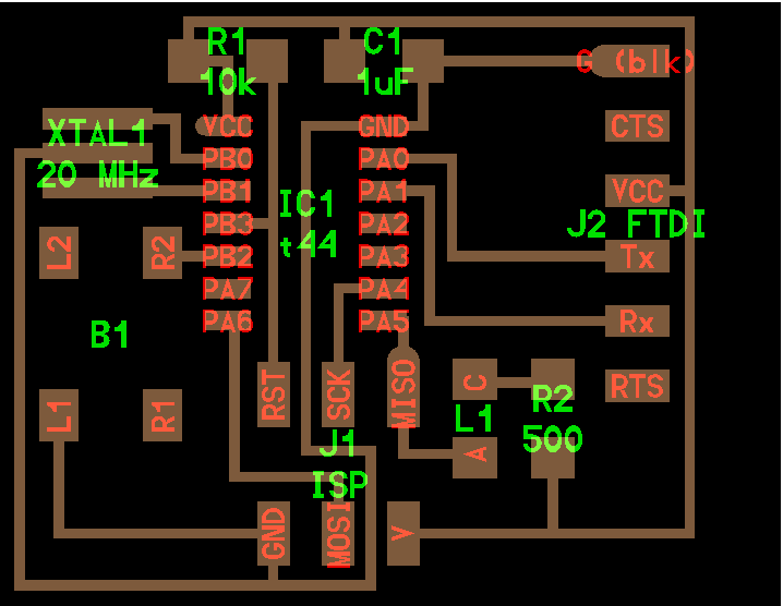
This is the image of the board

First thing I want to do is to make this board to send data through the serial and receive data from the interface of the computer.
I will program this board to turn the led on if it receive character F from the serial communication cable.
I will use the same code for the receiver board I made before in week 15.
The thing I will modify inhello.5.bus.c code which is node id I will make it F as I made the application to send F character so the board should receive F character to turn the led on.
This is the code I modify.
#define serial_port PORTA
#define serial_direction DDRA
#define serial_pins PINA
#define serial_pin_in (1 << PA0)
#define serial_pin_out (1 << PA1)

#define node_id 'F'

void get_char(volatile unsigned char *pins, unsigned char pin, char *rxbyte) {
   //
   // read character into rxbyte on pins pin
   //    assumes line driver (inverts bits)
   //
   *rxbyte = 0;
   while (pin_test(*pins,pin))
      //
      // wait for start bit
      //
      ;
   //
   // delay to middle of first data bit
   //
   half_bit_delay();
   bit_delay();
   //
   // unrolled loop to read data bits
   //
   if pin_test(*pins,pin)
      *rxbyte |= (1 << 0);
   else
      *rxbyte |= (0 << 0);
   bit_delay();
   if pin_test(*pins,pin)
      *rxbyte |= (1 << 1);
   else
      *rxbyte |= (0 << 1);
   bit_delay();
   if pin_test(*pins,pin)
      *rxbyte |= (1 << 2);
   else
      *rxbyte |= (0 << 2);
   bit_delay();
   if pin_test(*pins,pin)
      *rxbyte |= (1 << 3);
   else
      *rxbyte |= (0 << 3);
   bit_delay();
   if pin_test(*pins,pin)
      *rxbyte |= (1 << 4);
   else
      *rxbyte |= (0 << 4);
   bit_delay();
   if pin_test(*pins,pin)
      *rxbyte |= (1 << 5);
   else
      *rxbyte |= (0 << 5);
   bit_delay();
   if pin_test(*pins,pin)
      *rxbyte |= (1 << 6);
   else
      *rxbyte |= (0 << 6);
   bit_delay();
   if pin_test(*pins,pin)
      *rxbyte |= (1 << 7);
   else
      *rxbyte |= (0 << 7);
   //
   // wait for stop bit
   //
   bit_delay();
   half_bit_delay();
   }

void put_char(volatile unsigned char *port, unsigned char pin, char txchar) {
   //
   // send character in txchar on port pin
   //    assumes line driver (inverts bits)
   //
   // start bit
   //
   clear(*port,pin);
   bit_delay();
   //
   // unrolled loop to write data bits
   //
   if bit_test(txchar,0)
      set(*port,pin);
   else
      clear(*port,pin);
   bit_delay();
   if bit_test(txchar,1)
      set(*port,pin);
   else
      clear(*port,pin);
   bit_delay();
   if bit_test(txchar,2)
      set(*port,pin);
   else
      clear(*port,pin);
   bit_delay();
   if bit_test(txchar,3)
      set(*port,pin);
   else
      clear(*port,pin);
   bit_delay();
   if bit_test(txchar,4)
      set(*port,pin);
   else
      clear(*port,pin);
   bit_delay();
   if bit_test(txchar,5)
      set(*port,pin);
   else
      clear(*port,pin);
   bit_delay();
   if bit_test(txchar,6)
      set(*port,pin);
   else
      clear(*port,pin);
   bit_delay();
   if bit_test(txchar,7)
      set(*port,pin);
   else
      clear(*port,pin);
   bit_delay();
   //
   // stop bit
   //
   set(*port,pin);
   bit_delay();
   //
   // char delay
   //
   bit_delay();
   }

void put_string(volatile unsigned char *port, unsigned char pin, PGM_P str) {
   //
   // send character in txchar on port pin
   //    assumes line driver (inverts bits)
   // function that send stinges letter by letter
   static char chr;
   static int index;
   index = 0;
   do {
      chr = pgm_read_byte(&(str[index]));
      put_char(&serial_port, serial_pin_out, chr);
      ++index;
      } while (chr != 0);
   }
int main(void) {
   //
   // main
   //
  //DDRA &= ~(1 << PA3);
  // set PA3 as input in DDRA

  //PORTA |= (1 << PA3);
  // SET PULL UP RESISTOR IN PA3
  DDRA |= (1 << PA5);

  // set PA3 as output in DDRA
   static char chr;
   //
   // set clock divider to /1
   //
   CLKPR = (1 << CLKPCE);
   CLKPR = (0 << CLKPS3) | (0 << CLKPS2) | (0 << CLKPS1) | (0 << CLKPS0);
   //
   // initialize output pins
   //
   set(serial_port, serial_pin_out);
   input(serial_direction, serial_pin_out);

            //PORTB &= ~(1 << PB2);
               // PORTB |= ( 1<< PB2);
                //led_delay();
            //PORTB |= ( 1<< PB2);
            //PORTB &= ~(1 << PB2);
               // led_delay();


   //
   // main loop
   //
   while (1) {
      //get_char(&serial_pins, serial_pin_in, &chr);
     get_char(&serial_pins, serial_pin_in, &chr);

      if (chr == 'F') {
        PORTA ^= (1 << PA5);
                  }

              }
              }
Now the board is ready to receive character F to turn led on.
For making the interface I will use processing.py for making the interface.
This is the start screen of the program after I download it from the website.
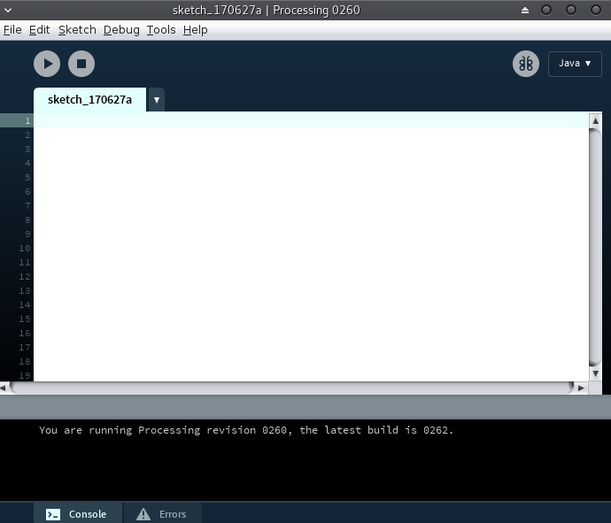
First I found the mode working is java and I want to programming using python.
So I download python and install it.
So now I have the python environment and it is ready for writing the code on it.
I start learning how to make background and rectangle on it.
This image show the code for making it.
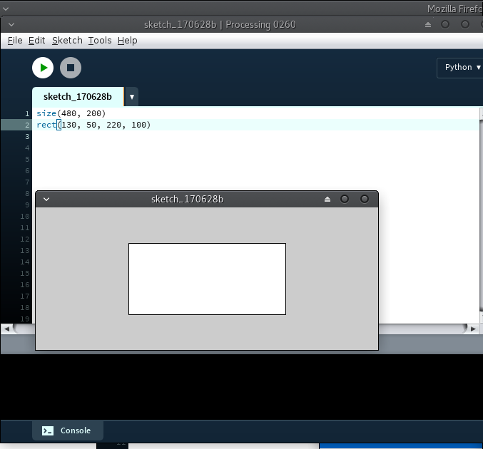
The second thing I want to do is to make a color for the main background and another color for the background of the rectangle . In this case as in examples I see I will use to functions.
def setup and def draw
After I finish writing the code I face the first problem like in the following image.
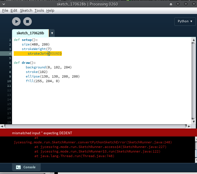
The solve of this problem is to make alignment of the statements carefully.
This the code of making a circle in side rectangle
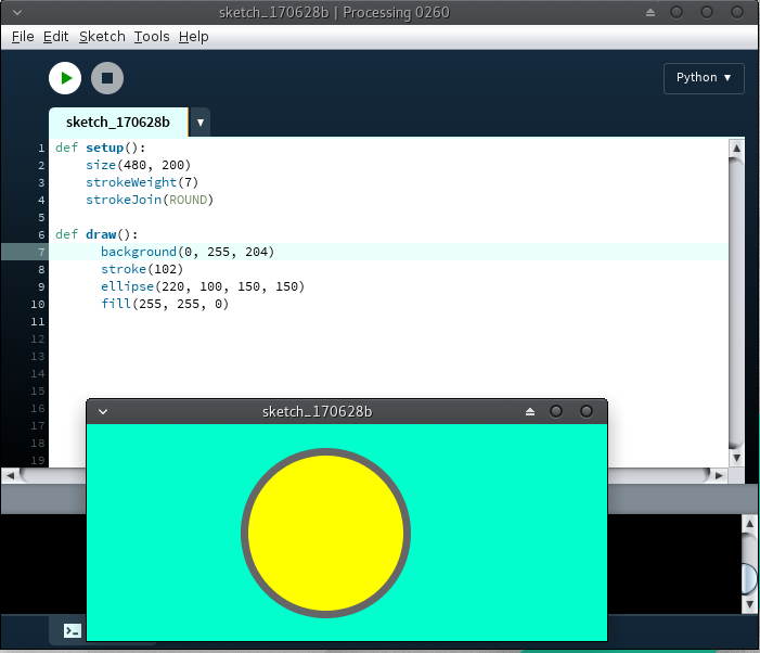
def setup():
    size(480, 200)
    strokeWeight(7)
    strokeJoin(ROUND)

def draw():
      background(0, 255, 204)
      stroke(102)
      ellipse(220, 100, 150, 150)
      fill(255, 255, 0)
The next thing I do is when I press the mouse the circle color change.
I make a white circle when I press the mouse it converted to yellow circle.
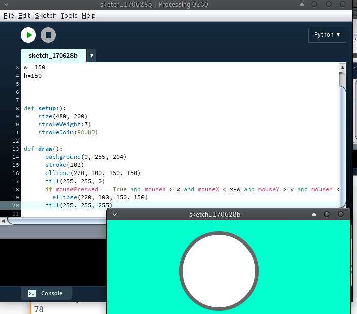
Here is the code I write
x= 220
y= 100
w= 150
h=150


def setup():
    size(480, 200)
    strokeWeight(7)
    strokeJoin(ROUND)

def draw():
      background(0, 255, 204)
      stroke(102)
      ellipse(220, 100, 150, 150)
      fill(255, 255, 0)
      if mousePressed == True and mouseX > x and mouseX < x+w and   mouseY > y and mouseY < y+h:
        ellipse(220, 100, 150, 150)
      fill(255, 255, 255)
Code for adding the text in the circle
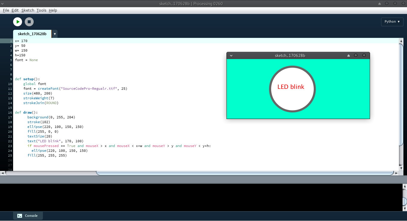
Here is the code I use
x= 170
y= 50
w= 150
h=150
font = None


def setup():
    global font
    font = createFont("SourceCodePro-Regualr.ttf", 25)
    size(480, 200)
    strokeWeight(7)
    strokeJoin(ROUND)

def draw():
      background(0, 255, 204)
      stroke(102)
      ellipse(220, 100, 150, 150)
      fill(255, 0, 0)
      textSize(20)
      text("LED blink", 170, 100)
      if mousePressed == True and mouseX > x and mouseX < x+w and    mouseY > y and mouseY < y+h:
        ellipse(220, 100, 150, 150)
      fill(255, 255, 255)
Now the last thing is to make the circle color change when it receive a charcter from the board through the serial cable.
So at first I will import the serial library in the programme so I can recive data from the board.
This is the final code I write in processing.py
add_library('serial')
x= 170
y= 50
w= 150
h=150
font = None


def setup():
    global font
    global port
    font = createFont("SourceCodePro-Regualr.ttf", 25)
    size(480, 200)
    strokeWeight(7)
    strokeJoin(ROUND)
    port = Serial(this, "/dev/ttyUSB0", 9600)

def draw():
      background(0, 255, 204)
      stroke(102)
      ellipse(220, 100, 150, 150)
      fill(255, 0, 0)
      textSize(20)
      text("LED blink", 170, 100)
      if mousePressed == True and mouseX > x and mouseX < x+w and mouseY > y and mouseY < y+h:
        rect(100, 30, 100, 60)
        port.write('F')
      fill(255, 255, 255)
Now I have receiver board and ready for receiving character from the serial communication and have the application that will interface the board.
The next step is that I connect the board to the computer so it can read data from application through the serial communication.
For making this connection I will use FTDI USB to serial adapter.
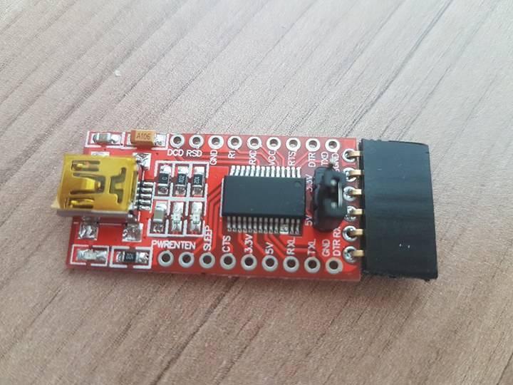
I use this adapter to communicate between the board and interface.
FTDI chip is range of USB to serial converter cable which provide connectivity between USB and serial UART interface.
After I connect the board to FTDI and make sure that receiver of the FTDI connect to the transmitter of the board and vice-versa I start click in the button I made on the interface and when I press it turn the led on.
When I press the button in the interface it send character F through the serial communication to the board the board see the character and if the charcter match the id the board have inside the micro controller it turn the led on
When I let the mousepad not pressed it stop send charcter through the serial cable and the board will not receive any character so it turn the led off.
This video show the LED blink when I press the mousepad.
During this week I have problem that I can not receive any character from the serial communication.
I try to find solution of the problem by checking the code but the code is right , I check the soldering of the board but it have no issues and finally I find that neil use 8 mhz oscillator and I used 20 mhz oscillator so I should change the bit delay on the code as I don't know the exact value of the bit delay I decide to change the oscillator to 8 mhz and it work finally.