For making this board i will use kokopelli to modify the board
I will use kokopelli to add button to PB1 so I can control the LED in the second board.

This week assignment is to design and build a wired or wireless network connecting at least two processors.
For this week assignment I will make a networking between two boards one have push button and another one have LED.
The first board I will modify on Neill bridge board.
For making this board i will use kokopelli to modify the board
I will use kokopelli to add button to PB1 so I can control the LED in the second board.
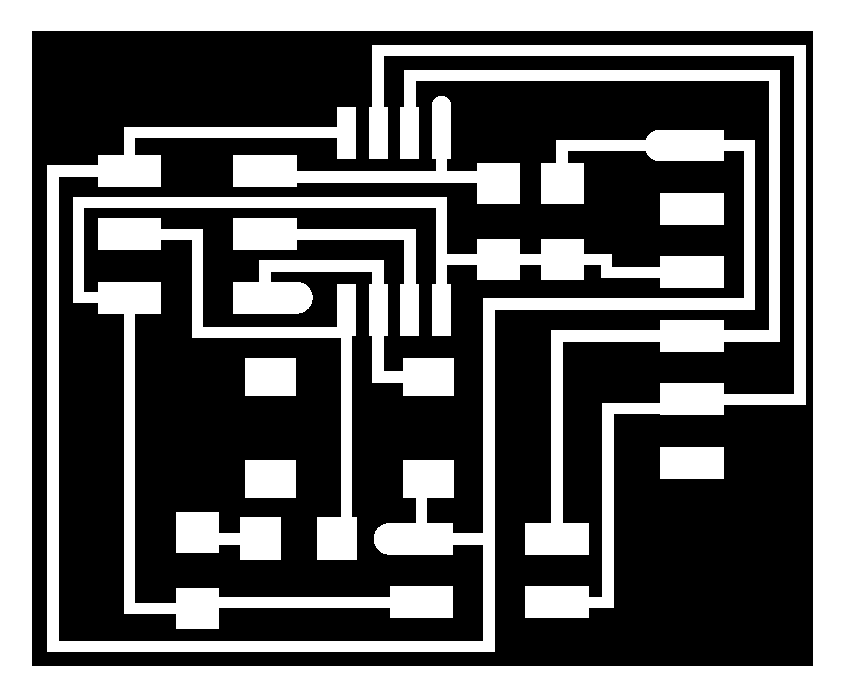
After I finish modifiying the board I have the traces file and outline file
This is the image of the traces
This is the image of outline

After having the the traces and outline of the board I will go to to generate the rml files of the traces and outline.
The next step is that I send the rml files to cnc to mill the board.
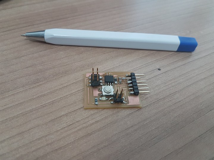
After machine finish I will soldering the components to the board.
This is the final image of the board.
For the second board I will use the board of electronic design assignment
The board image

For making the communication between the two board I will use serial communication between the boards.
For making the communication between the two boards I will make a protocol that every board will have an id and the master board will send character to the slave board through the serial cable and when the slave board receive the character it will act according to the programming code.
For making this connection I will use FTDI USB to serial adapter.
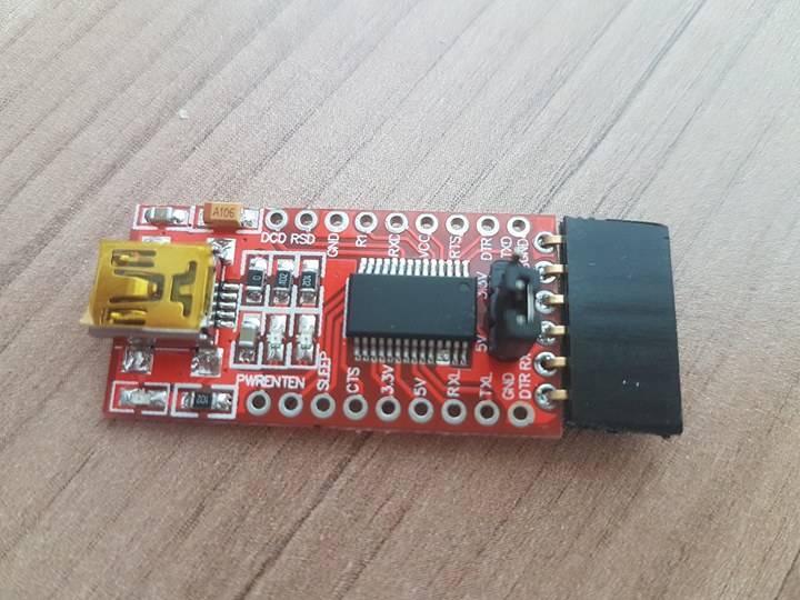
I use this adapter to communicate between the board and computer.
FTDI chip is range of USB to serial converter cable which provide connectivity between USB and serial UART interface.
This first try to make networking so I decide to make connection that allow me to send character to the computer through the serial cable and see the result on arduino IDE serial monitor.
For making this I will modify on hello.5.bus.c this is the Neil code for making transmission.
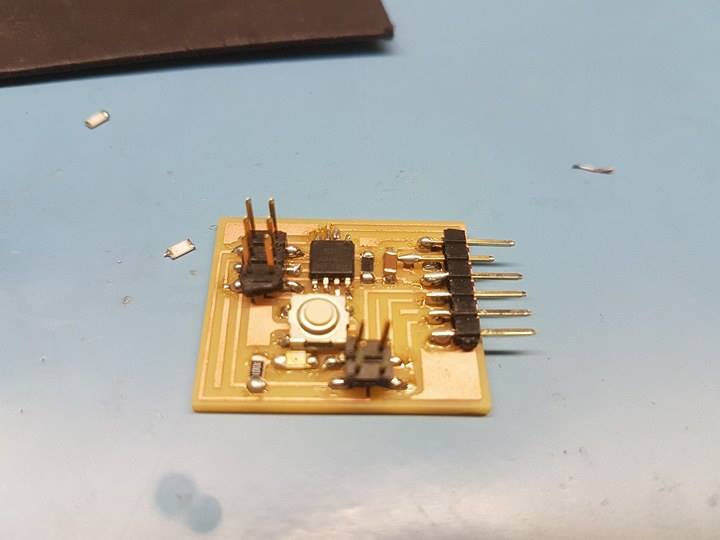
This image show the modification I do on the board.
#define bit_delay_time 100 // bit delay for 9600 with overhead


#define led_port PORTB
#define led_direction DDRB
#define led_pin (1 << PB0)

#define serial_port PORTB
#define serial_direction DDRB
#define serial_pins PINB
#define serial_pin_in (1 << PB3)
#define serial_pin_out (1 << PB4)

#define node_id 'M'
    DDRB |= (1 << PB4);
    DDRB &= ~(1 << PB1);
    PORTB |= (1 << PB1);

//  output(led_direction, led_pin);
//   set(led_port, led_pin);

   //
   // main loop
   //
   while (1) {


    if (PINB & (1<<PB1)) {

    }
    else {
    put_char(&serial_port, serial_pin_out, 'M');
    _delay_ms(1000);
    }


      }
   }
In this code I define that the receiver of the board connected to PB3 and and transmitter connected to PB4.
What I do also is that I define the node id which is the character I will send through the serial communication in my case it is M and also I write in the code that if I press the button which connected to PB1 it will send the character which is defined M .
This video show the board when sending character to the computer and seeing the results.
For this task I will use the second board which is the board of week 6 assignment.
What I want to do is that when I sending character from the serial monitor of the arduino the board will receive the character and turn the led on
As I mad in transmitter board I will modify hello.bus.45.c Neil code to make the led tirn on when it receive character M from the serial
#define serial_port PORTA
#define serial_direction DDRA
#define serial_pins PINA
#define serial_pin_in (1 << PA0)
#define serial_pin_out (1 << PA1)

#define node_id 'M'
while (1) {

    get_char(&serial_pins, serial_pin_in, &chr);
       _delay_ms(1000);
     if (chr == node_id) {
       PORTA ^= (1 << PA5);
                 }

             }
             }
First problem I have is that when I send the character from the serial it does not toggle the led.
So I rewrite the code and check the transmitter and receiver pins at the end I found that the problem is in the crystal oscillator as I use 20 mhz and it should be 8 mhz.
I change the oscillator

After I change the oscillator the board still not Receiving the character last thing I do and the board work is that I make fuses to be 8mhz
This video show the board when Receiving the character and toggle the led
()
After I send character to the computer now it is the time to send character from one board and the second board respond and the led will turn on.
I use the transmitter code I make before that send character M when I press the button.
When the second board will receive the character it turn the LED on.