This week assignment is to add a sensor to micro controller board that we have designed before and read sensor values.
In this week assignment I try to photo resistor to my board and peizzo so when the amount of light on the photo resistor decrease the peizzo will give sound.
I will design the board that have 5 photo resistor and peizzo puzzer when the amount of light in the photo resistor decrease the peizzo will make sound.
Steps of designing the board is final project page
This is the image of board
After I finish designing I export the pngs files of the traces and outline of the board
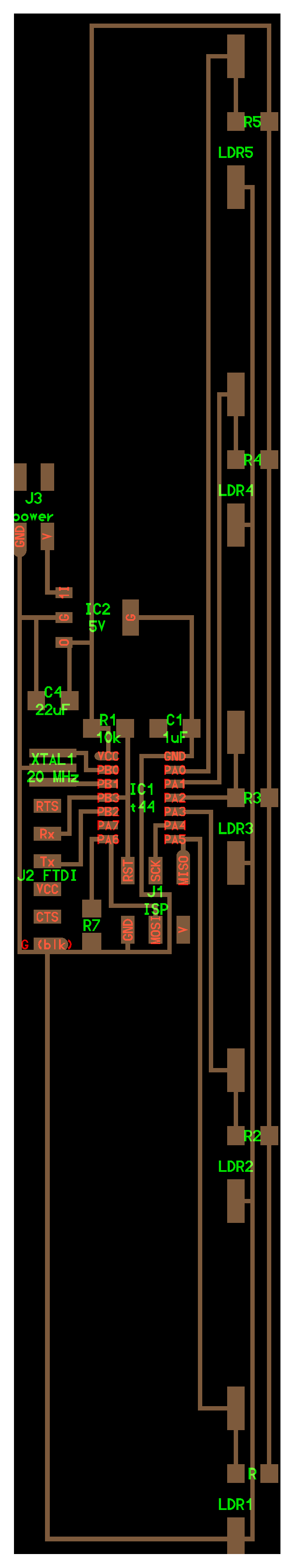
The image of the traces

This is the image of the outline.

outline file.png
Milling the board and soldering it are in [Final project page]((http://archive.fabacademy.org/archives/2017/fablabuae/students/164/final.html)
Image of the board after finish soldering

Full steps of making the board is in final project page
In this assignment I will make analog to digital converter for the first photo resistor which is connected to PA0 and another photo resistors I make the ADC in final project page
So at first I read the data sheet of the attiny to know how to make analog digital converter.
At first I know that no need to activate analog to digital converter on pin PA0 as it was activated by default.
Analog to digital converter I can make it only on ports of A (from PA0 to PA7) and it is 10 bit ADC, so its resolution is 1024.
AS I have resolution of 1024 and the ranges should be from 50 khz to 2oo khz I should activate ADC prescaler.
For putting predivision factor it depend on the oscillator I have in the board and in my case I put 20 MHZ so the predivision factor will be 128.

In this case I don't need to select multiplexerm as I coonect photo resistor in pin PA0 and the voltage reference is vcc.
So I will start programming now
To start programming, I started with Neil's code Hello.light.45 and I modified the ADC code.
At first I measure the voltage of the sensor when it is in the dark the sensor voltage is 4.6 volt and when the sensor under the light of laser beam the voltage is 1.03 volt.
So I make the peizzo to work when the LDR in the normal light and stop working when the LDR under the light of the laser. So for making the peizzo working in the normal light so its ADC value is 220.
I measure the voltage of ldr on the dark and it's value is 4.6 volt which mean resolution 1023 and at the full light the voltage is 1.03 volt which mean 1 resolution and the voltage at the normal light is 2.55 from calculating I find the ADC value is 300.
This is the part of code I modify
if ( ADC > 300 )
{
PORTA |= (1 << PA6);
}

else
{
PORTA &= ~(1 << PA6);
}
This video show the ldr working
Files to downlod