The goal of this week assignment is to add an output device to the micro-controller board that I have made before.
What I decide to add is that I will add servo motor .
The servo motor
The servo is built right inside the motor unit and has a positionable shaft, which usually is fitted with a gear . The motor is controlled with an electric signal which determines the amount of movement of the shaft.
The most important part in the servo to be known is how servo motor be controlled.
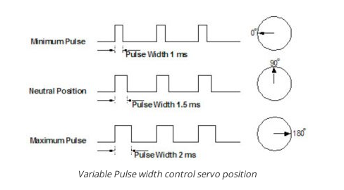
The below image show how to control the servo motor :
from this image I find that make the servo go from any position to 0 degree it need pulse with pulse width 1ms.
To move the servo 90 degree I need pulse with pulse width 1.5 ms.
To move the servo 180 degree (maximum movement) we need pulse with pulse width 2 ms.
I found all information about the servo during the following link Servo-motor
After I understand the principles of how the servo motor work it is the time this week assignment.
Designing the circuit of the servo:
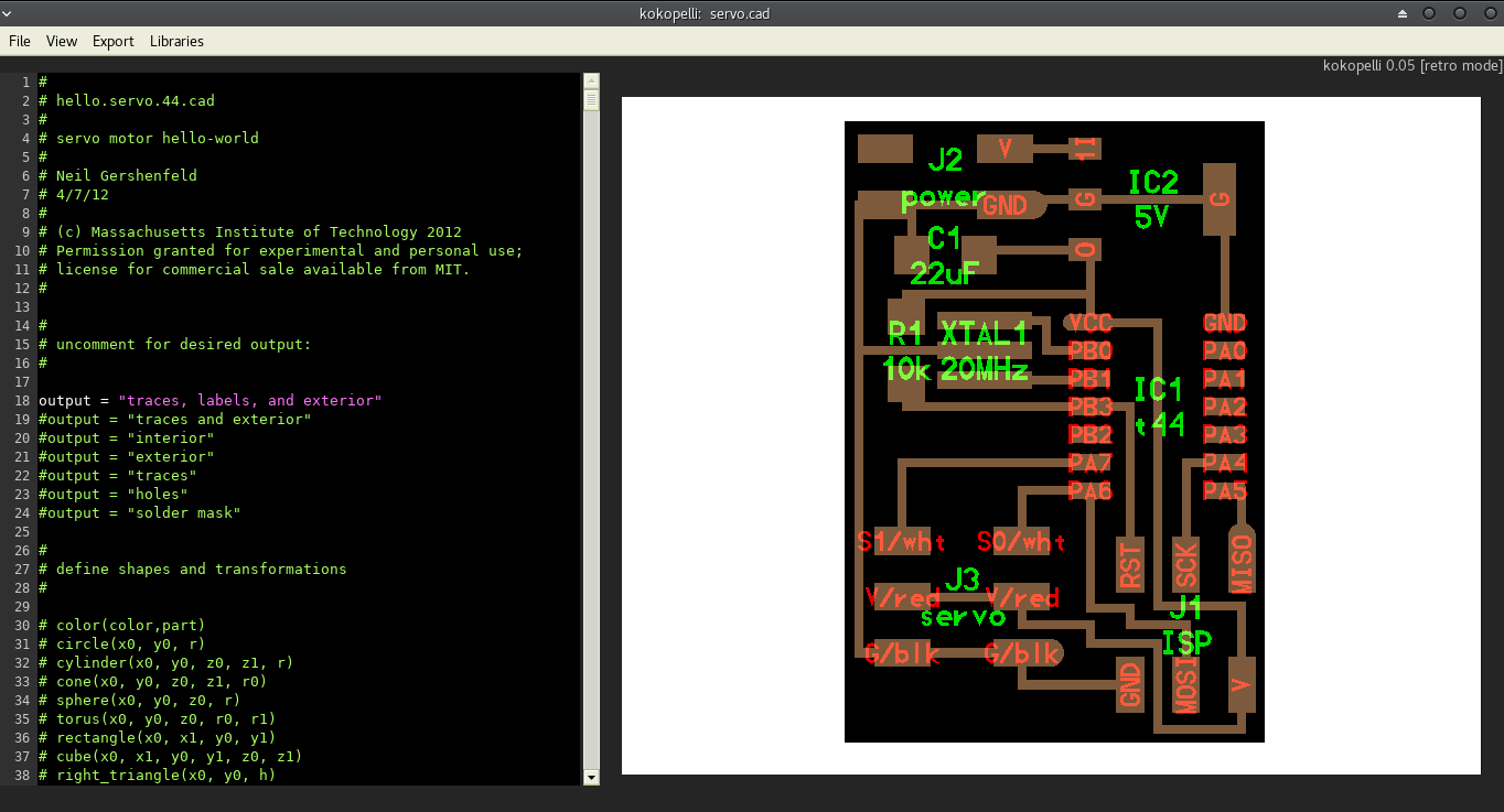
As usual on fab academy I use kokopelli for making all electronic circuits. I go to fab academy page and go to output assignment and choose servo and then download the file of Neil board.
This is the link of the board Hello.servo.44.cad
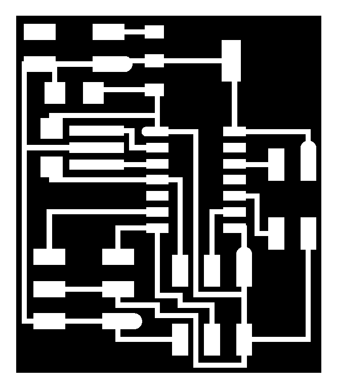
After downloading it and I save it as Servo board.cad and open it using kokopelli. This is the image after opening servo board using kokopelli
As I plan to use this board in networking assignment so I decide to put place for serial communication.
What I need to do in the board is that I want to make it wider so I can but what I want as it is very narrow. SO first thing is that I make the board more wider by increasing the width of the board from 0.75 inch to 0.95 inch.
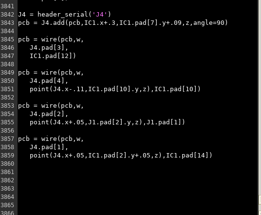
After increasing the width I start to the connector for the serial communication which consist of 4 pins.
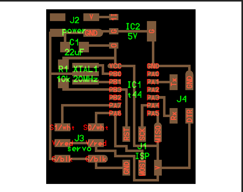
The following images show how to put the connector and how to connect it on the board.
This image describe the place where I put the header which is on the right side of the board, then I start to connect it to the Attiny 44 pins.
As this header serial consist of 4 pins - first pin for VCC and connected to the VCC of J1 ISP.
- Second pin is the ground and connected to the GND IC1 t44
- Third is the transmitter and connected to pin PA1 in IC1 t44 - Fourth is the receiver and connected to pin PA3 in IC1 t44
This image for the board after finish editing
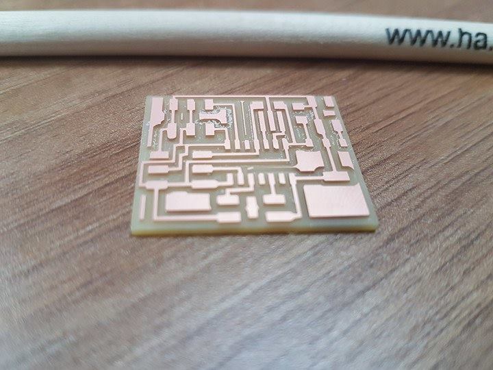
Milling the board:
The first step before milling the board is to export traces and outline file from the original file . For exporting the traces at first I should choose the output as traces and exterior and then make exporting the image with resolution 25 pixel.
The PNG file of the traces
With the same way I export the PNG file of the outline.
The PNG file of the outline
With the same way I have learned in the previous weeks in electronic assignments I will use Fab Module to generate the Rml files of the traces and outline of the board.
Then I send this Rml files to monofab machine to start milling.
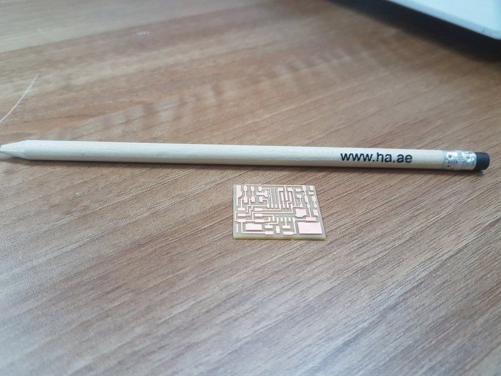
This is the board after finish milling.
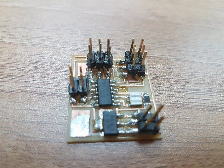
Soldering time:
By using the soldering skills I have learned in the previous electronic weeks assignments I start soldering the board.
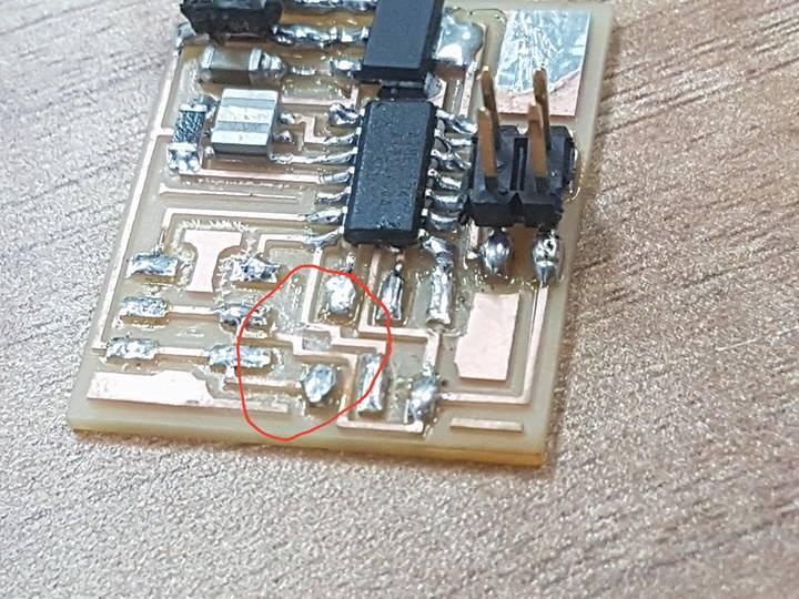
This is the board after finish the soldering
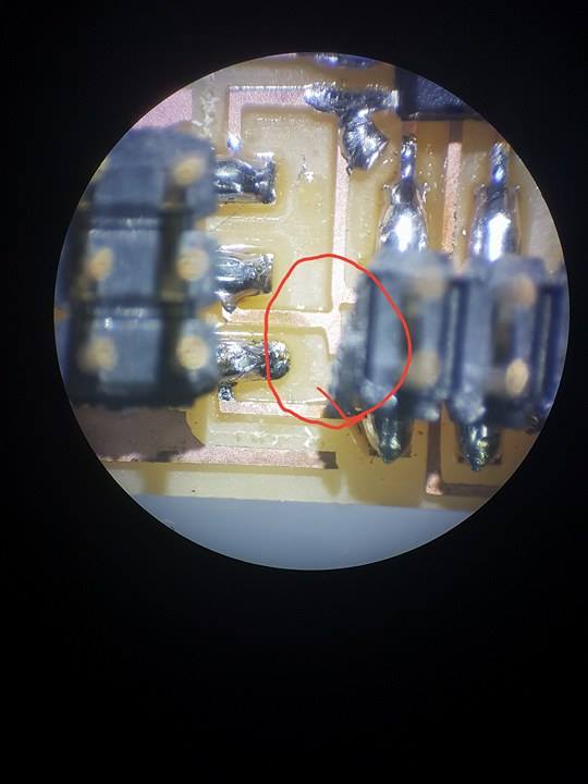
Problem I have faced after soldering:
The first problem I have faced is during checking the short circuit and open circuit in the board I found that there are two line that they are shorted they are very near to each other and the machine can not make separation between them.
The solution is that I use the cutter to make separation between the two lines. This image of the board after removing the error.
After I finish removing the error I try to connect the board with ISP board and servo to test it.
Programming time:
For Programming this board I will use my ISP as a programmer.I download neil code for moving the servo from the archive that will make the servo move from 0 degree to 180 degree. This is the link of the code in archive
I modify the code to make the servo move from 45 degree to 135 degree.
What I modify in the code
In this code for making the servo work, the servo should talk pulse width modulation that will make the servo move.
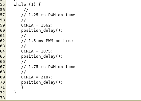
So from calculation between the pulse needed and the degree of movement I find that for making the servo move 135 degree it need 1.75 ms PWm on time and for making the servo move 45 degree it need 1.25 ms PWm on time.
After that What I do is that I need to know the equal value in OCIRA for each degree.
For 1.25 ms the OCIRA is 1562
For 1.75 ms the OCIRA is 2187
After making the calculation I modify on the code This image show what I change in the code
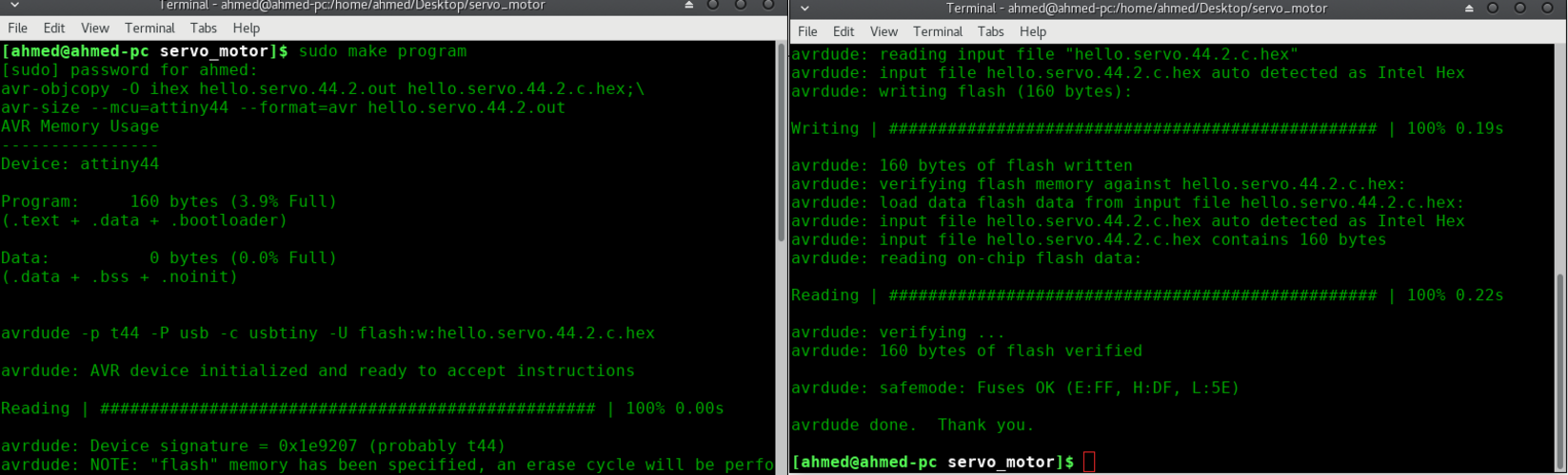
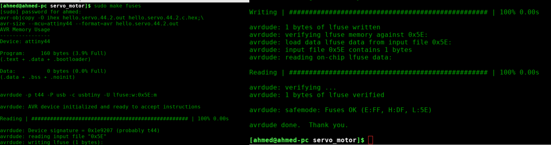
After finish editing the code I save it and download a make file. Now it is time to upload the program in to the board using the ISP. There are two command to upload the program to the board.
- Sudo make program
- sudo make fuse
these images show that the two commands are successfully executed .
Now the board is ready for use.
This video show how the motor move between 45 degree angle and 90 degree angle and 135 degree angle.
After I see the servo work I will see the variance on the signal between the angles on oscliscope in this video

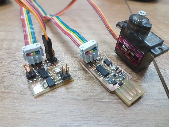
 Now the board is ready for use.