My final project is a robotic fish that can discover what happen in the depth of the sea. Robotic fish will record video of what happen inside the sea and I can see the video on my phone
I have changed my final project from robotic fish to musical instrument called Semsemya.
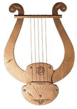
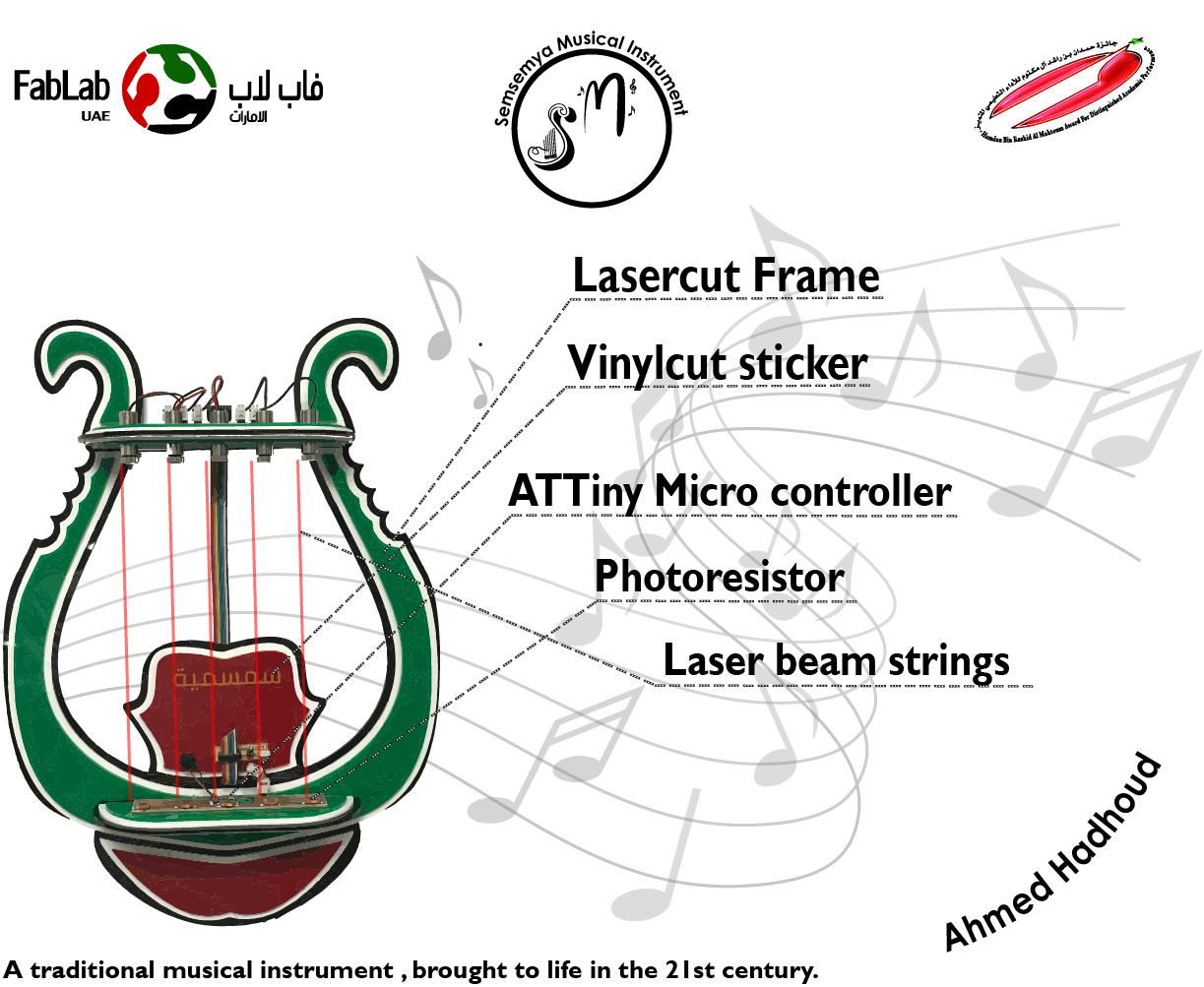
The main idea for this project is to make musical instrument that can teach any one how to play music, this instrument consist of five strings and every string have a specific tone,when any one put his hand on the place of the string the computer will generate out the specific tone of the string, so it is easy to learn how to play on it.
This is the image of the instrument:
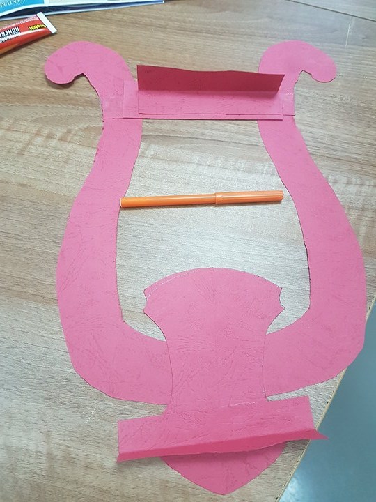
This is initial design of the instrument, with this initial design I know the shape of the instrument and the size of it.
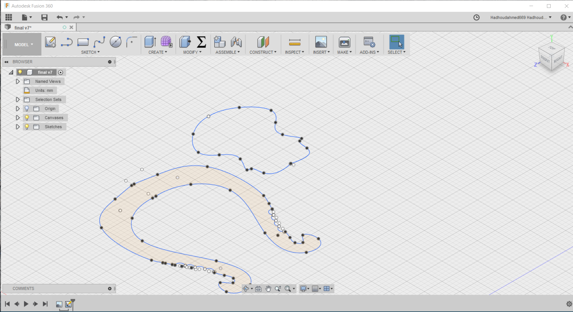
For making the sketch of the frame I will use Fusion-360 for making the design.
This image show the initial design of the frame
After making this design I export this design in DXF extension.
then I cut this design using laser cutting machine.
This video show the laser cutting machine cutting the frame.
This is the image of the frame when the machine finish cutting.
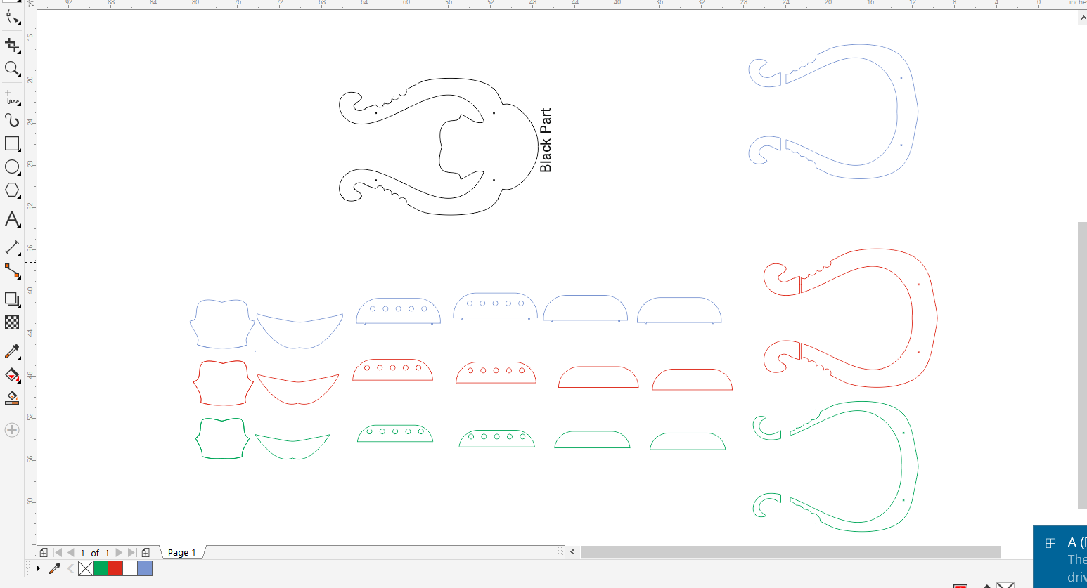
After I make this design I find that if I make it of multi layers of acrylic with different colors that refers to our fab lab logo.
So what I do is that I use Fusion-360 sketch parameter called offset to make offset of each part I have 4 times so I have 4 layers with different sizes of each part I have.
After I have finish the design I will cut it again in acrylic using laser cutter.
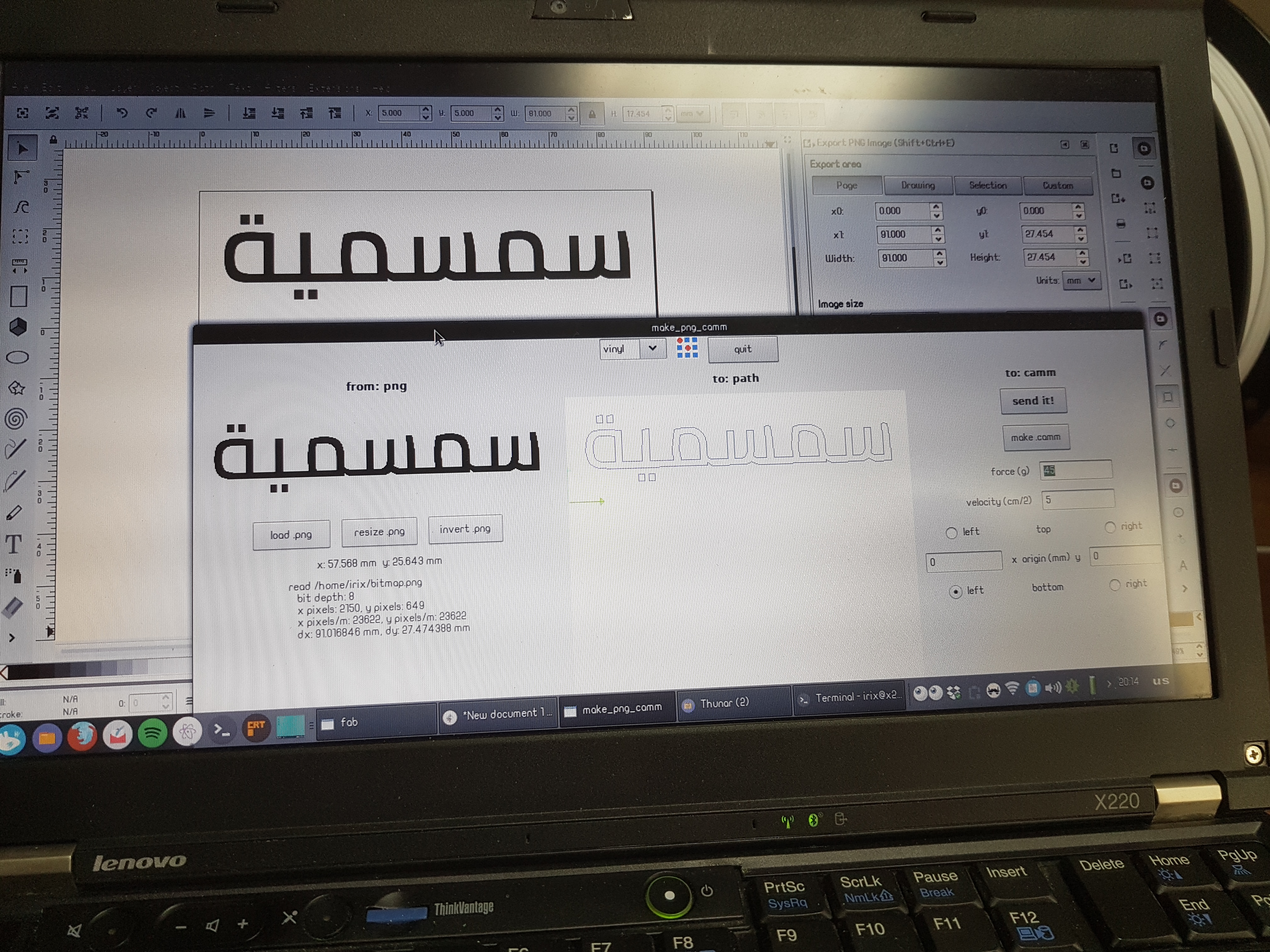
For making the logo of my final project I decide to make it using vinyl cutter which we have in our fablab.
Designing the logo
For designing the logo I will use 2D software Corle Draw to make the logo.
This is the image of the logo.
After finish the design of the log I will cut it using Vinyl cutter at first I put the roll then I make alignment of the roll inside the machine and start cutting.
By using the skills of how to make the logo I have learned in week 3 during fab academy I will make the logo.
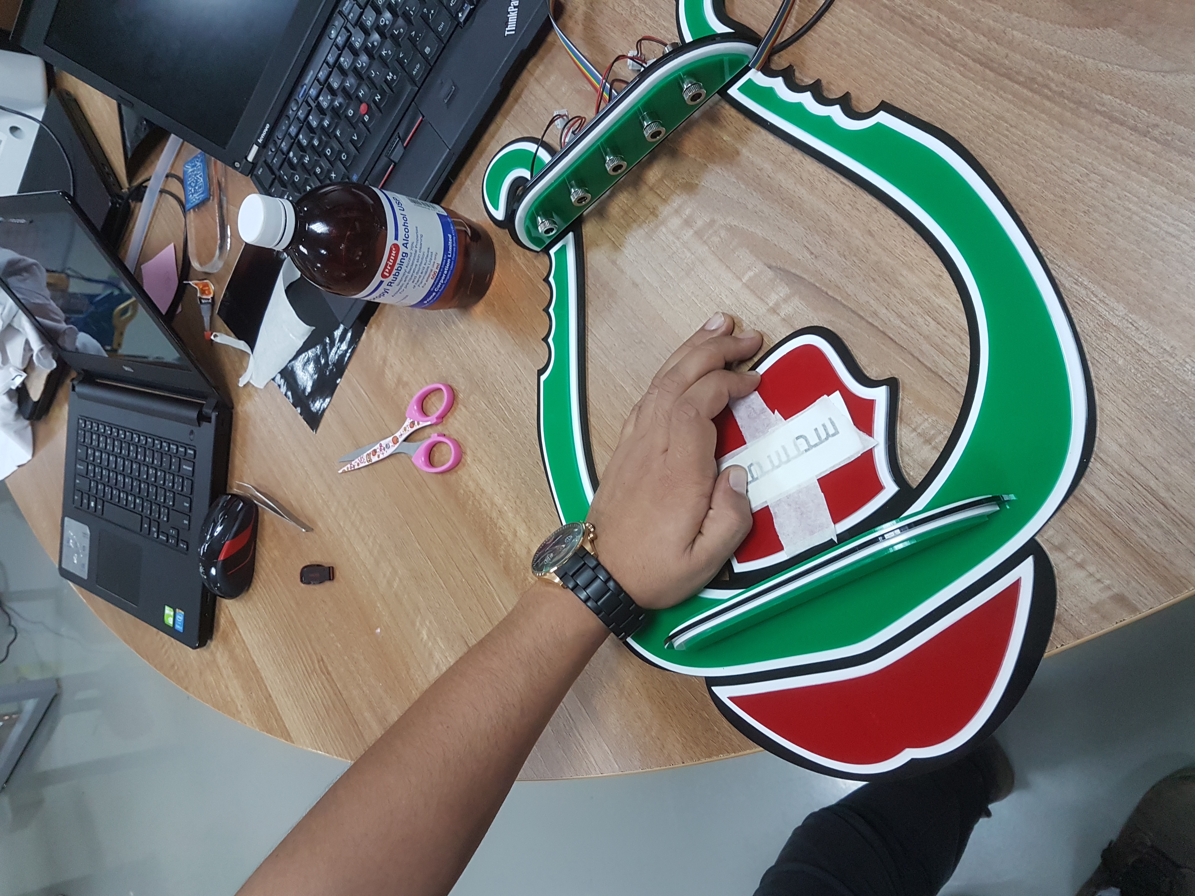
The following image show how to stick the logo to the instrument.
For making this part I will use also fusion-360 for making the design
This image show the designed part. After I finish the design I export it in stl format and send it to cura software which is maintained by 3D printer manufacturer Ultimaker and this is the type of printer we have in the lab Now I have the design in the Sd card and ready to print it. After making the calibration of the printer, the printer is ready for printing the design
After I cut all parts using the laser cutting machine
This is the image of all parts I cut
So for assembling all parts together I will use chloroform to stick the parts to each other.
I will use chloroform as it is best to make the pieces of acrylic to be stick to each other.
The following video show how I use chloroform to stick the part to each other.
For sticking two acrylic part to each other I shold make them vert tight to each other and then put little amount of chloroform and hold it for 15 second and they will be sticky to each other.
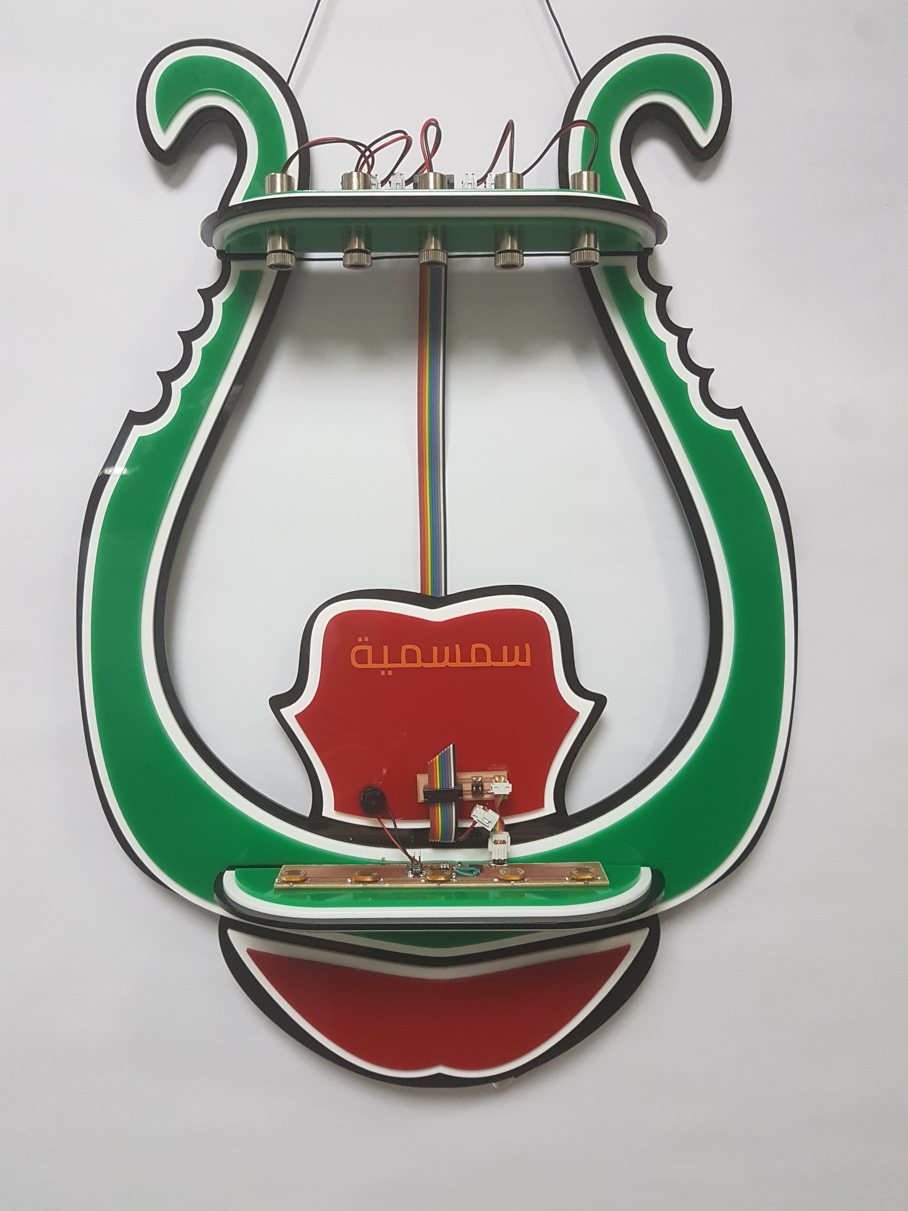
The problem I have during assembling is that the upper part which hold the laser beams is heavy and can not fixed using chloroform so I put some support to it to make it fixed.
This is the final image after I finish assembling.
Electronic section
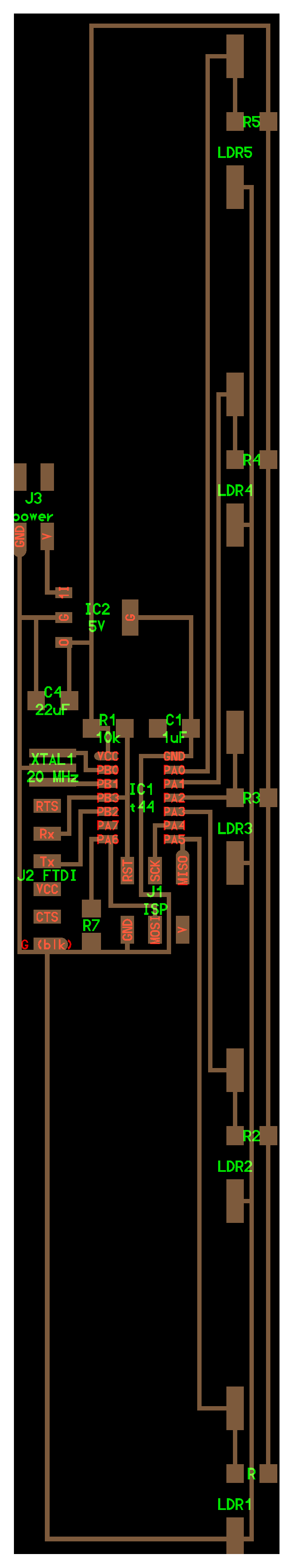
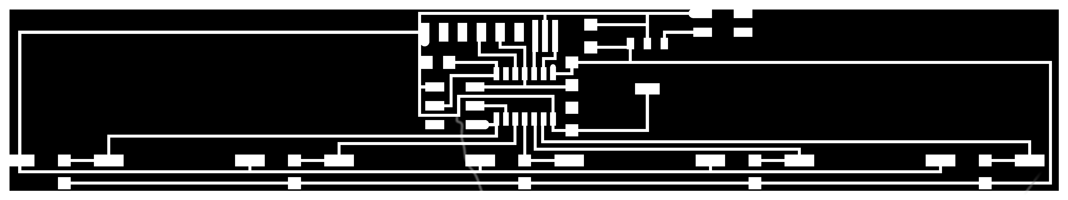
Designing the main board
For making the electronic board I will use kokopelli this software I use in fabricating all my board during fab academy but this is the hardest board I make during fab academy as I build it from start only have the attiny 44 from Neil board and I add everything and make all wire connection
As I use LDR and there is no pads of it in code, so I Make pads special for the LDR
This image show how to make special pads for LDR using kokopelli
For adding the pads first I take the measurements of the place that I will put the LDR on it.
Second thing is the LDR have two legs so I need to pads and I calculate the distance between them.
Third thing is the shape of the pad and in my case I choose it as cube
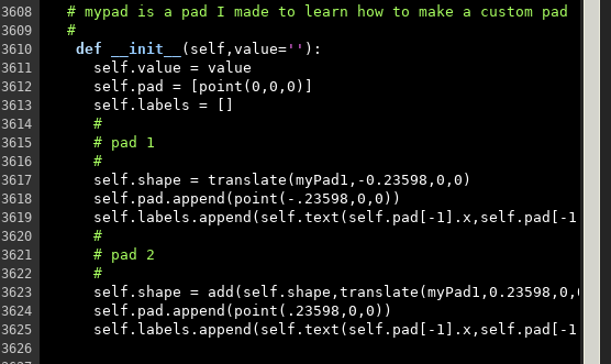
So this is the code in kokopelli to add special pads for the LDR.
``` # mypad is a pad I made to learn how to make a custom pad
After I have the PNGs files of the trace and outline of the board I will use fabmodules to obtain the rml file using the same skills I have learned in electronic design week during fab academy.
Now I have the rml files and I will use the cnc machine to mill the board.
I will use the skills for configuring the machine I have learned during fab academy
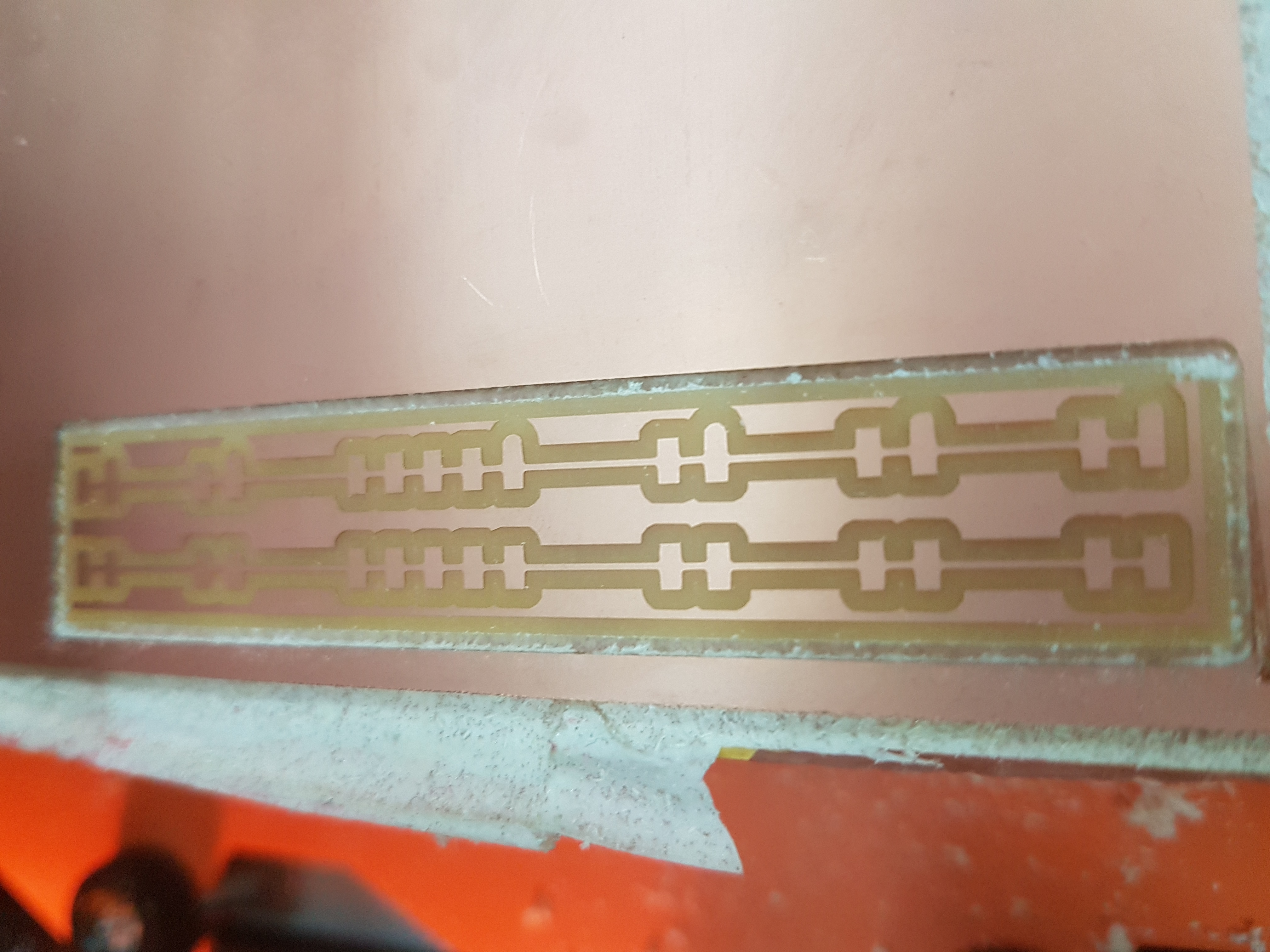
After the machine finish this is the image of the board.
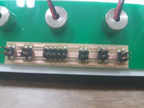
soldering the board.
This image show the board after soldering all electronic component.
Making board to distribute the power
I make this board to distribute the power to all lasers and also to the board.
By using the same skills I make this board by using kokopelli software.
This part I will program the board that if the Photoresistor detect that the light on it decrease it will give special sound related laser beam I cut its light.
At first Photoresistor is analog device so I should convert the analog signal of it to digital signal.
Define also all LDR as inputs and also I define the notes special for the buzzer.
In the while function I define that if the value of the LDR connected to PA0 for example play note gfc
As the note I have is
char notes[] = "ccggaagffeeddc "; // a space represents a rest
int beats[] = { 1, 1, 1, 1, 1, 1, 2, 1, 1, 1, 1, 1, 1, 2, 4 };
int tempo = 180;
So with changing the notes I put I change the tone.
After I finish the code and make command sudo make program to upload the code into the board.
After uploading succeed I find that the sound came from the piezzo is very ugly I check every thing and change the note but sound still ugly.
The last thing I do and succeed is that I change the peizzo.
Neil comments during the presentation.
He like the project and the only comment from him is that the slide have a little information and I should modify it.
So I modify the slide and put definition of each part of the instrument, the logo and breif history of it.

 After I finish the design I export it in
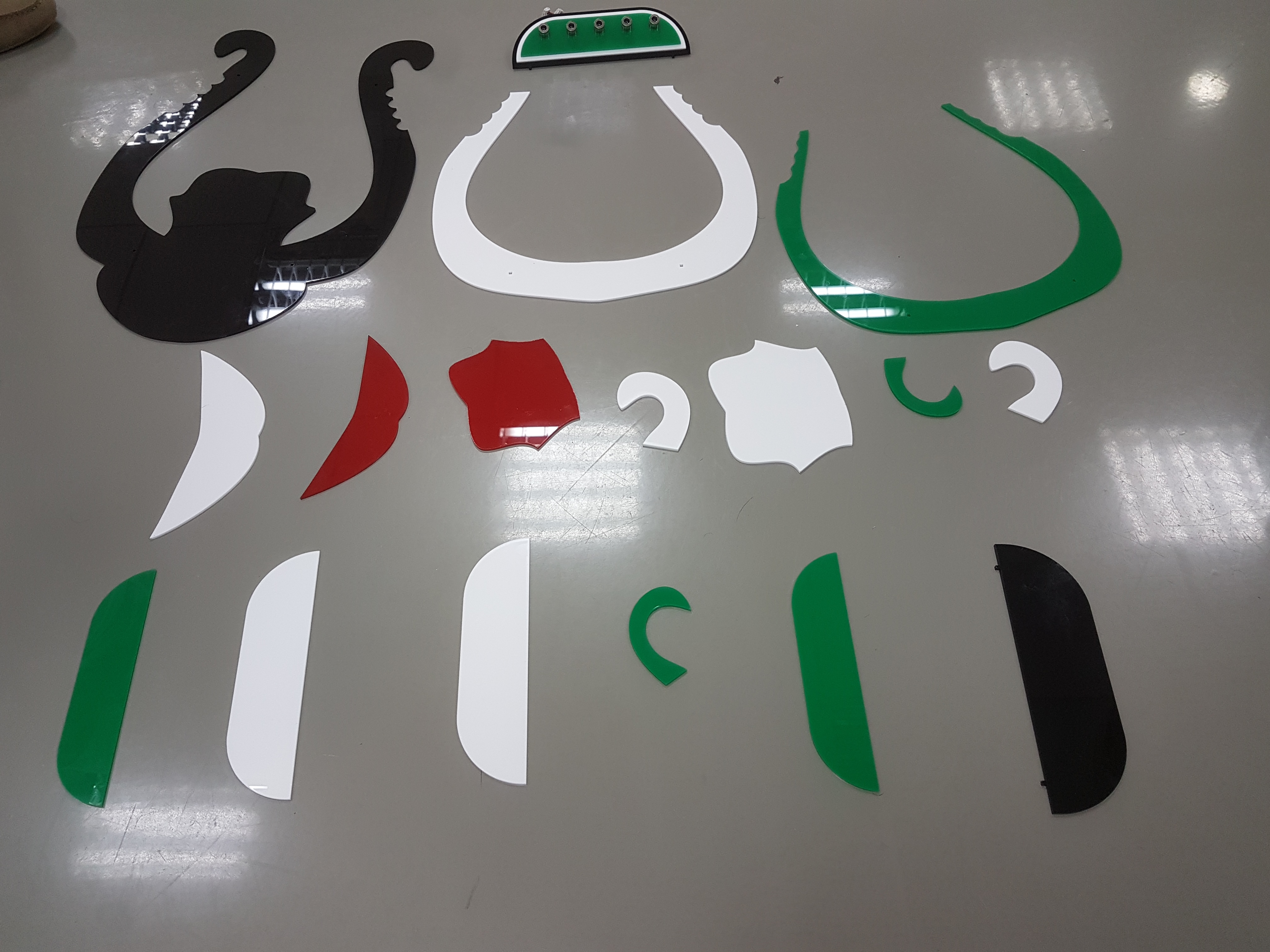


