Communication via I2C Protocol
For this week's assignment, I got design and build a wired & /or wireless network connecting at least two processors. Im planing to work with I2C Protocol to do communication between 2 boards.
The Inter-integrated Circuit (I2C) Protocol is a protocol intended to allow multiple “slave” digital integrated circuits (“chips”) to communicate with one or more “master” chips. It only requires two signal wires to exchange information.
This doc gives good detailing to the concepts.
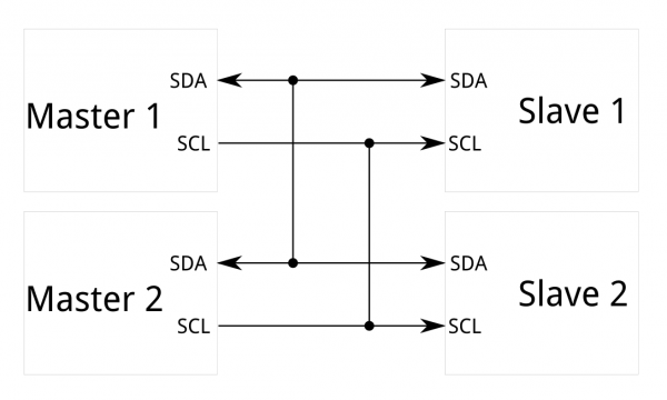
Each I2C bus consists of two signals: SCL and SDA. SCL is the clock signal, and SDA is the data signal. I²C uses only two bidirectional open-drain lines, Serial Data Line (SDA) and Serial Clock Line (SCL), pulled up with resistors. Typical voltages used are +5 V or +3.3 V, although systems with other voltages are permitted.
Board Schematics, Designs and PCB assembly
This week's work was pending for me.. So I'm actually completing this weeks assignment after I have completed my Project week.
I'm using Wire.h to implement this.
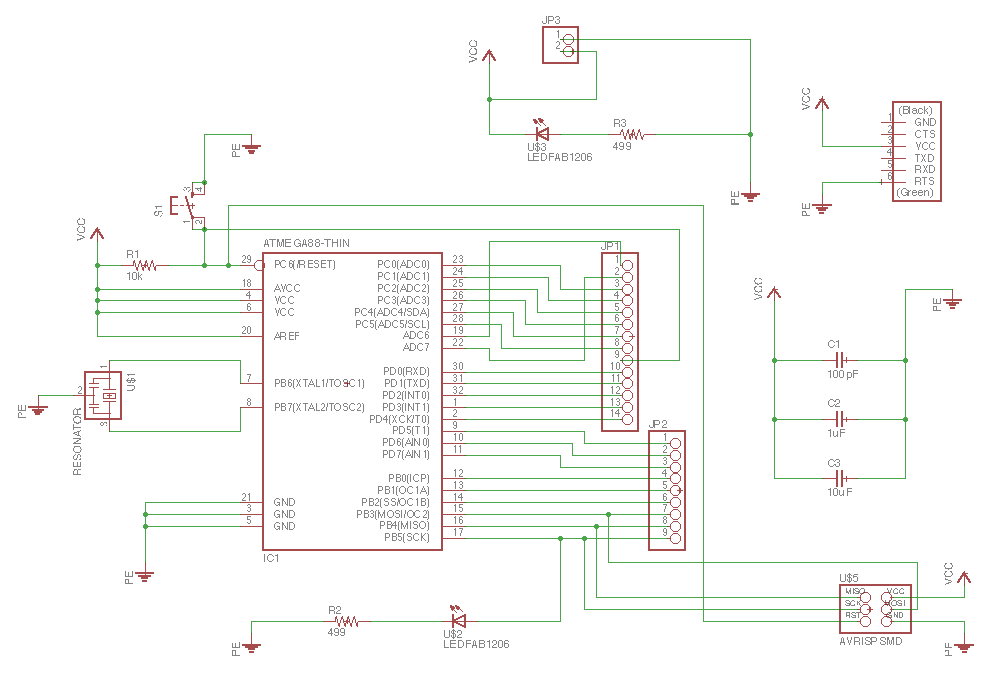
So the boards I'm using are both based on Satsha kit which I designed and milled on other weeks' work. The schematic diagram for both are almost the same. The following documentation is also from Interface and Application Programming week.
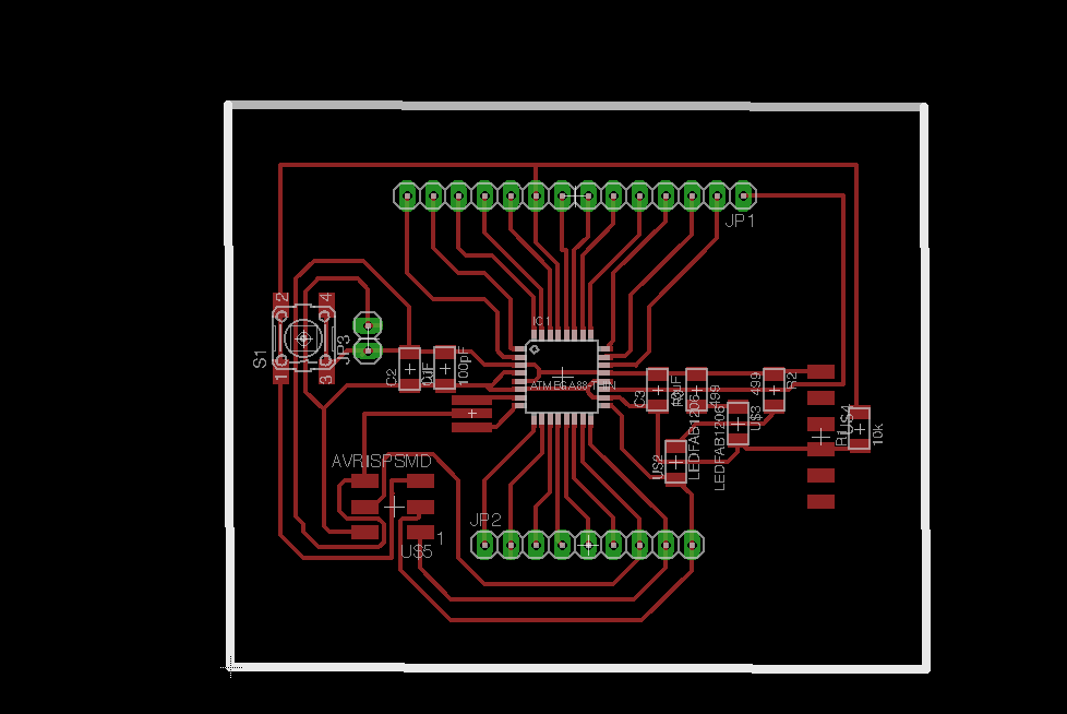
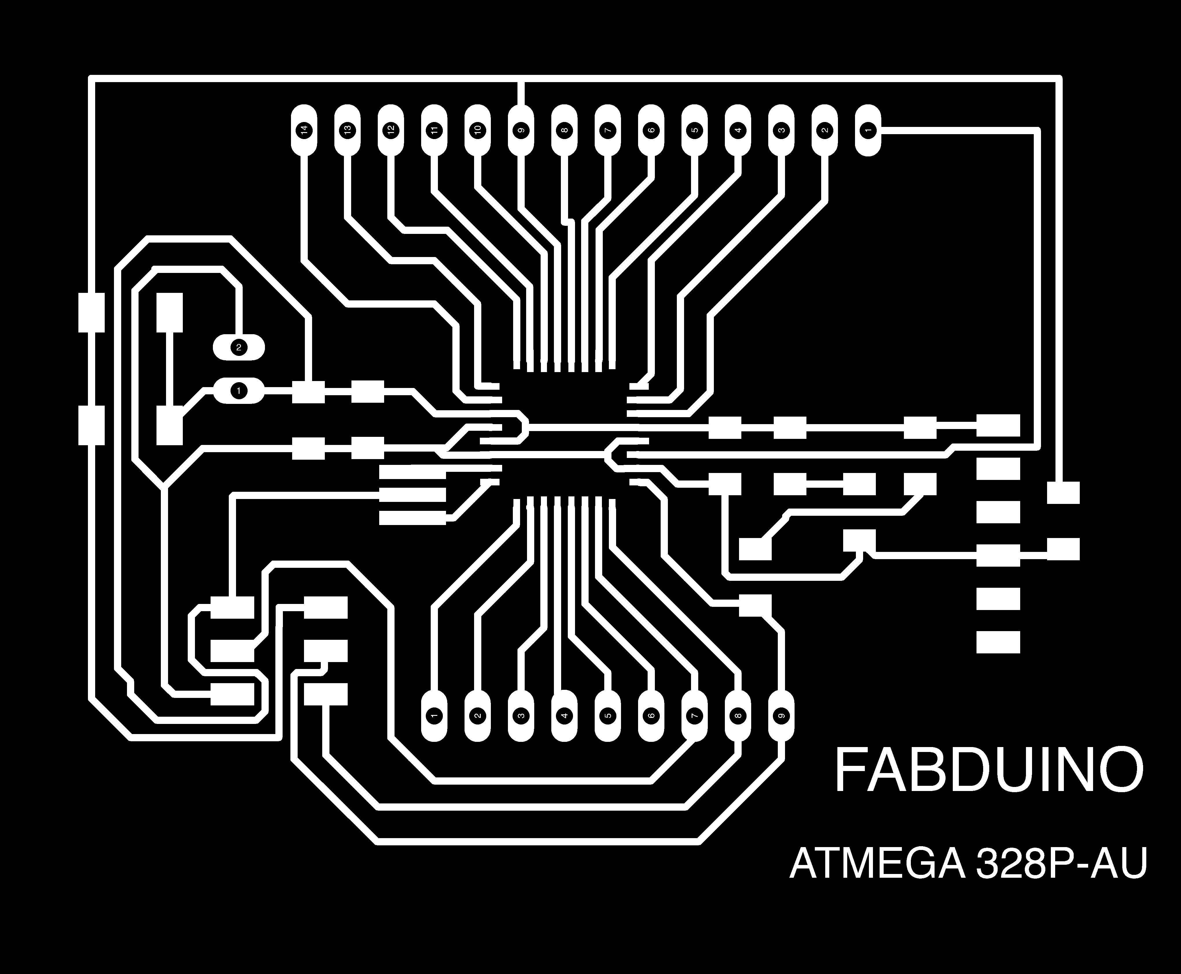
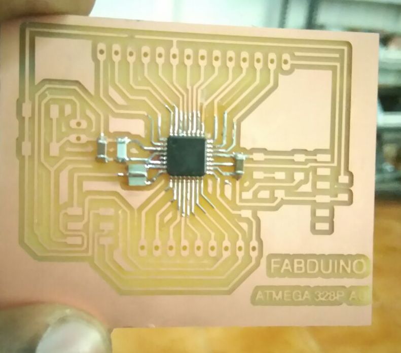
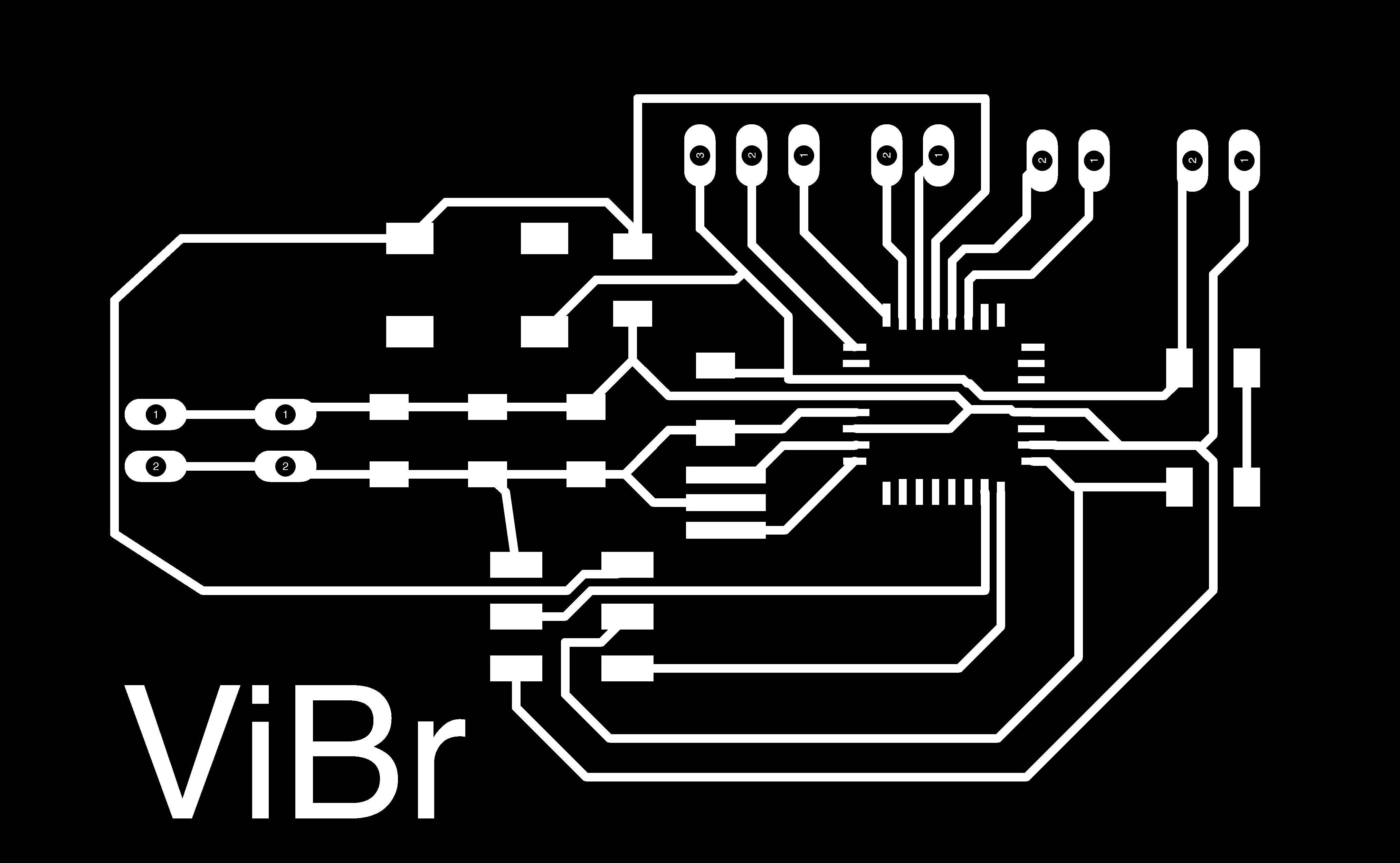
I exported the board trace and cut outline for the Fabduino board I created.
I used the fab modules to mill my design. Following are the screenshots I took when initiating the milling and cutting.
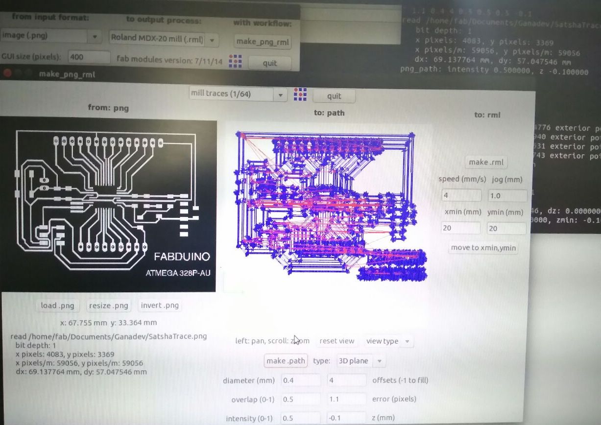
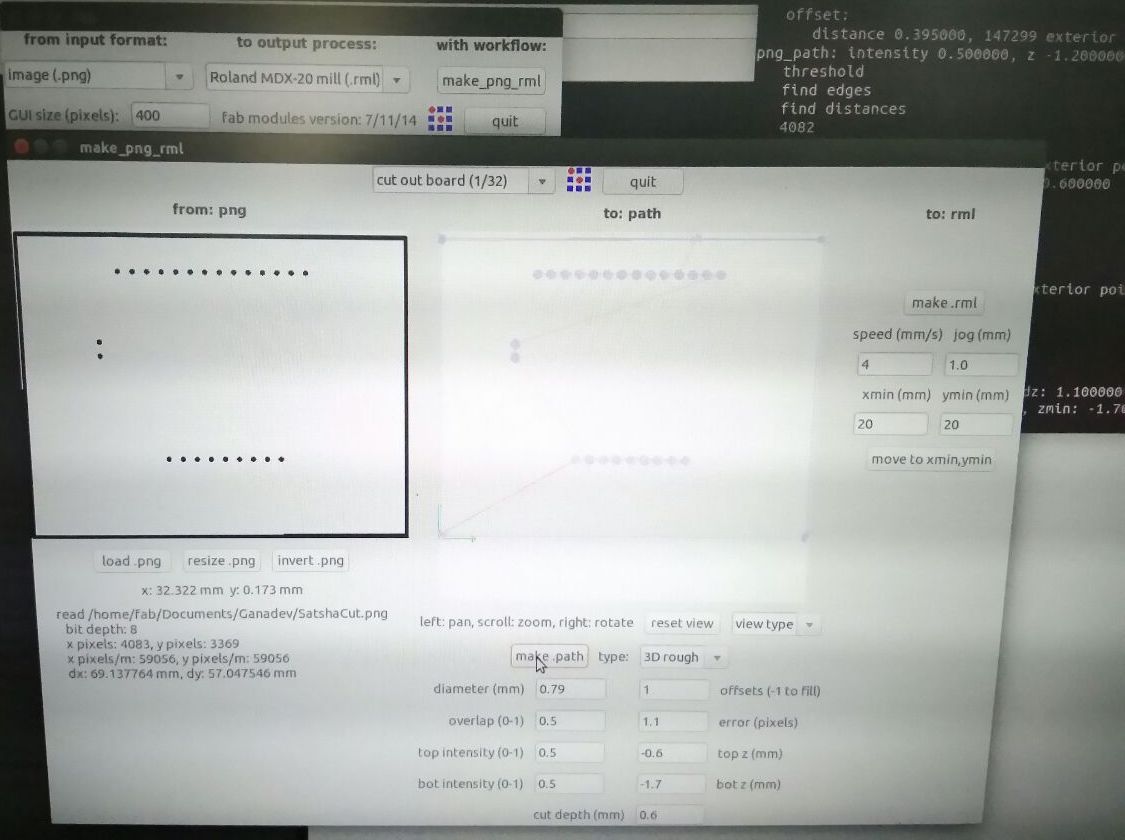
After milling and cutting out the board,
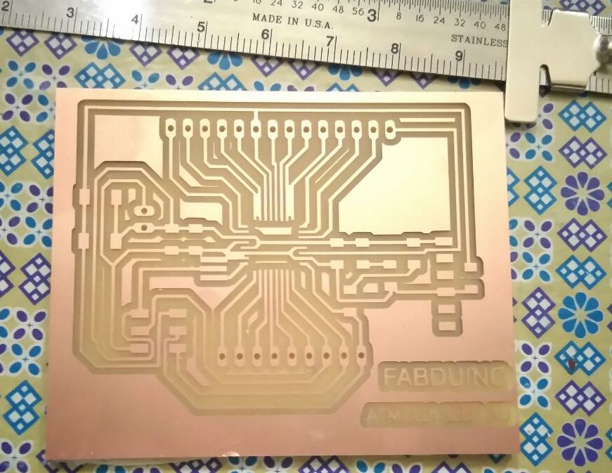
There are some traces that were not separated. I had to manually cut out those traces.
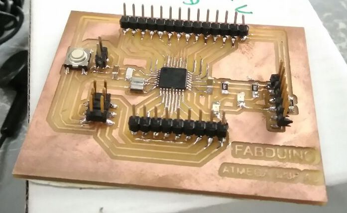
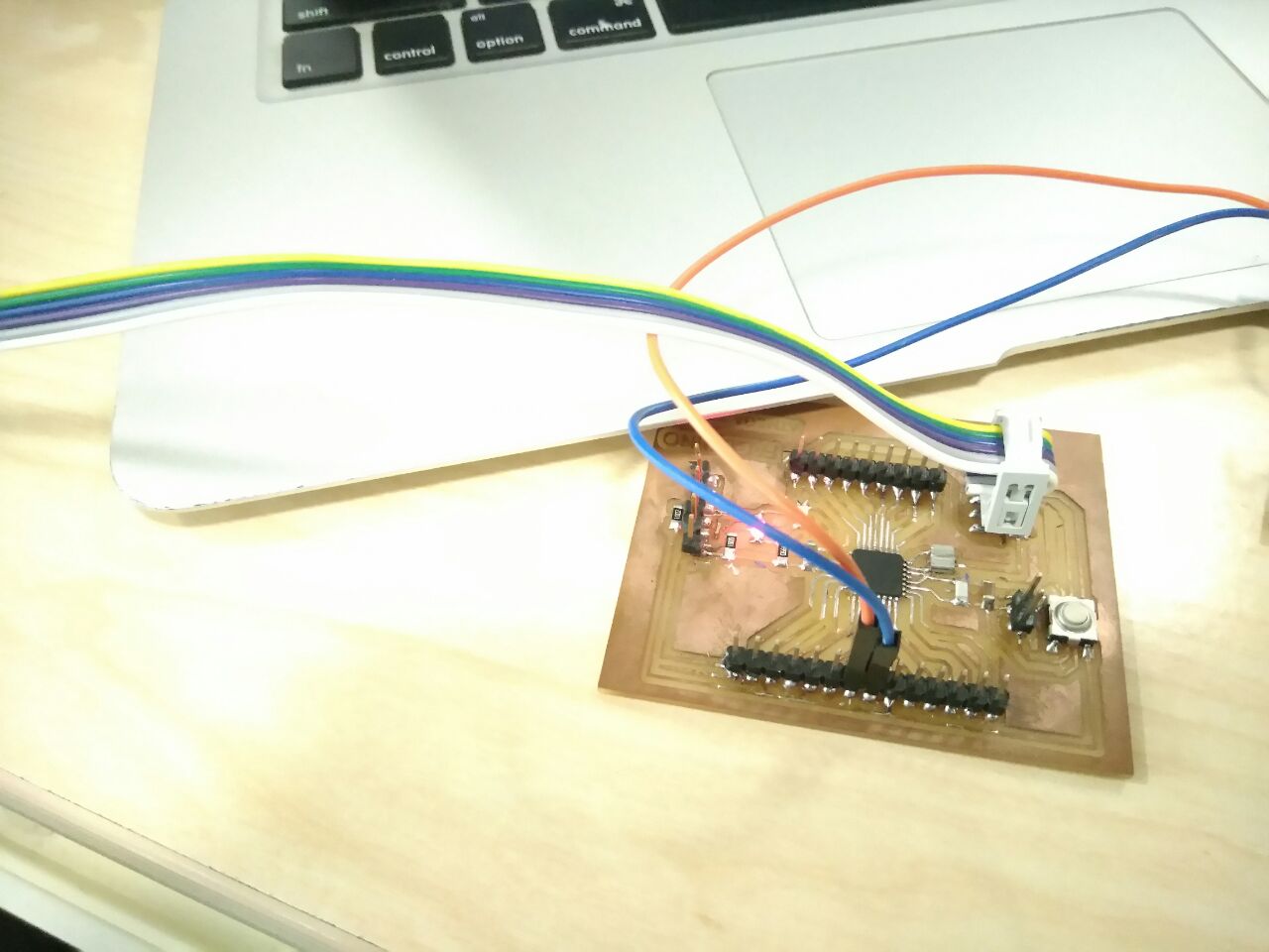
After collecting the components,
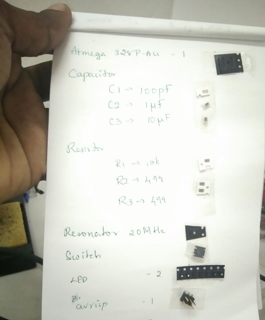
Soldering was challenging as the traces were small and so close, and but was able to get it all assembled neatly.
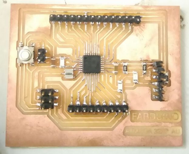
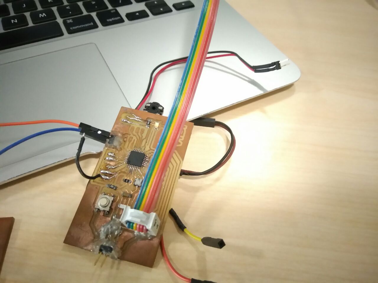
The second satsha board design is shown below,
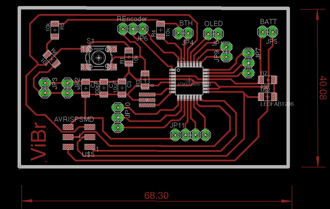
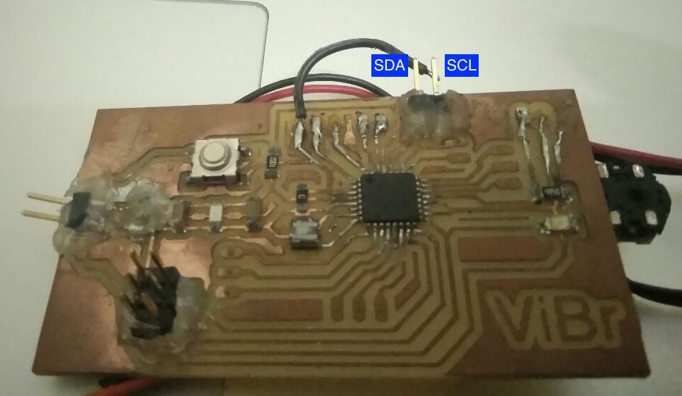
This board was done during my project week. After milling and assembling the components,
Programming the I2C master and I2C slave.
I found a code to test I2C between arduino boards, I used those and updated those code to run on my satsha boards,
\
The following is the code for I2C master,
// Wire Master Writer
// by Nicholas Zambetti < http://www.zambetti.com>

// Demonstrates use of the Wire library
// Writes data to an I2C/TWI slave device
// Refer to the "Wire Slave Receiver" example for use with this

// Created 29 March 2006

// This example code is in the public domain.


#include < Wire.h>

void setup() {
  Wire.begin(); // join i2c bus (address optional for master)
}

byte x = 0;

void loop() {
  Wire.beginTransmission(8); // transmit to device #8
//  Wire.write("x is ");        // sends five bytes
//  Wire.write(x);              // sends one byte
  Wire.write(x);
  Wire.endTransmission();    // stop transmitting

  x++;
  delay(500);
}
The following is the code for I2C slave,
// Wire Slave Receiver
// by Nicholas Zambetti < http://www.zambetti.com>

// Demonstrates use of the Wire library
// Receives data as an I2C/TWI slave device
// Refer to the "Wire Master Writer" example for use with this

// Created 29 March 2006

// This example code is in the public domain.


#include < Wire.h>

void setup() {
  Wire.begin(8);                // join i2c bus with address #8
  Wire.onReceive(receiveEvent); // register event
  Serial.begin(9600);           // start serial for output
}

void loop() {
  delay(100);
}

// function that executes whenever data is received from master
// this function is registered as an event, see setup()
void receiveEvent(int howMany) {
//  while (1 < Wire.available()) { // loop through all but the last
//    char c = Wire.read(); // receive byte as a character
//    Serial.print(c);         // print the character
//  }
  int x = Wire.read();    // receive byte as an integer
//  Serial.println(x);         // print the integer
//  Serial.println(x%5);
  if (x%5 == 0)
  {
    digitalWrite(13, HIGH);
  }
  else
  {
    digitalWrite(13, LOW);
  }
}
The slave with address #8 will only receive the transmission from the master,
Wire.begin(8);
So my slave board would light up when master value that is transmitted is divisible by 5,
The following is the setup I used to work on networking, I connected the SDA & SCL of the master IC to SDA & SCL of the slave IC respectively
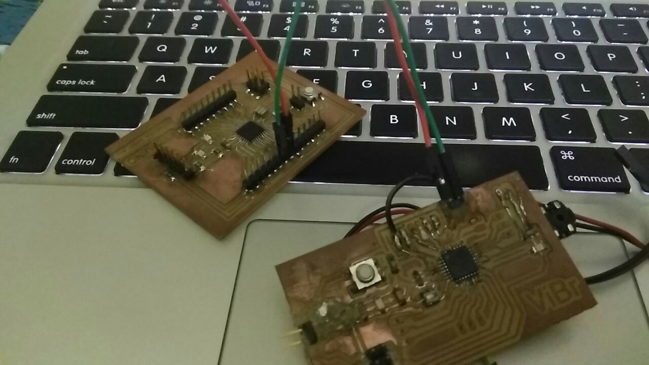
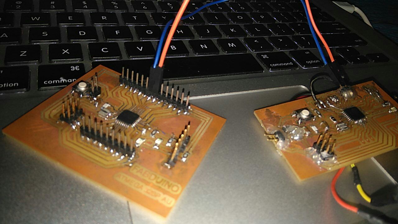
and powered both the boards using my computer via a couple of fabisp.
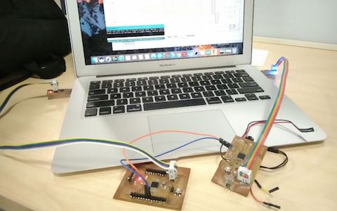
In the video, the second board is the slave, and the orange led on it lights up on very value send from the master board that is divisible by 5 (check out the led light on the board on the right side),
The video for the same,
SatshaTrace.png
SatshaCut.png
Satsha.sch
Satsha.brd
Original Design Files from project week
ViBr.sch
ViBr.brd
ViBrTrace.png
ViBrCut.png