Networking and Communications
This weeks assignment is to design and build a wired &/or wireless network connecting at least two processors. My plan is to use the I2C protocol
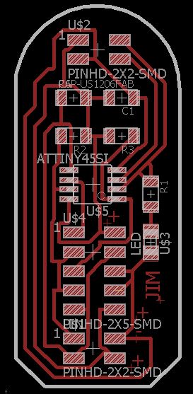
Design of the Board
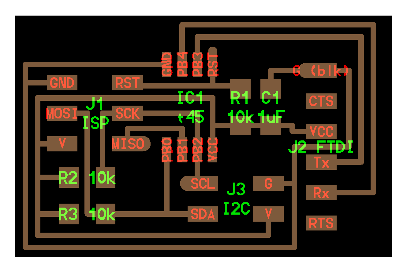
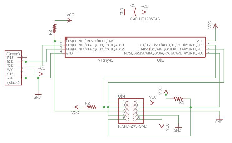
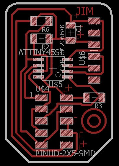
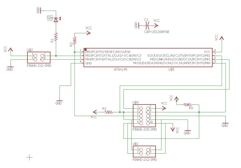
I used Autodesk Eagle to Design the Board for this week. The board is based out of Neil's board available here. First I made the Master board and then the Node board. The schematics and Board designs are in the images below.
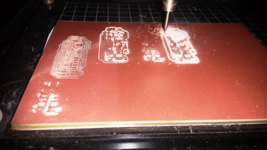
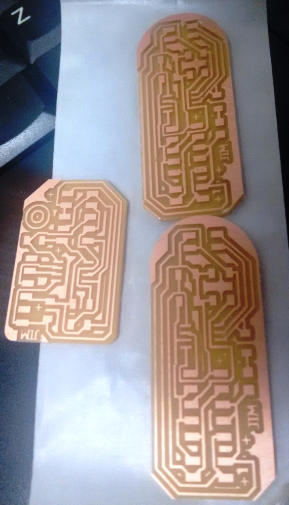
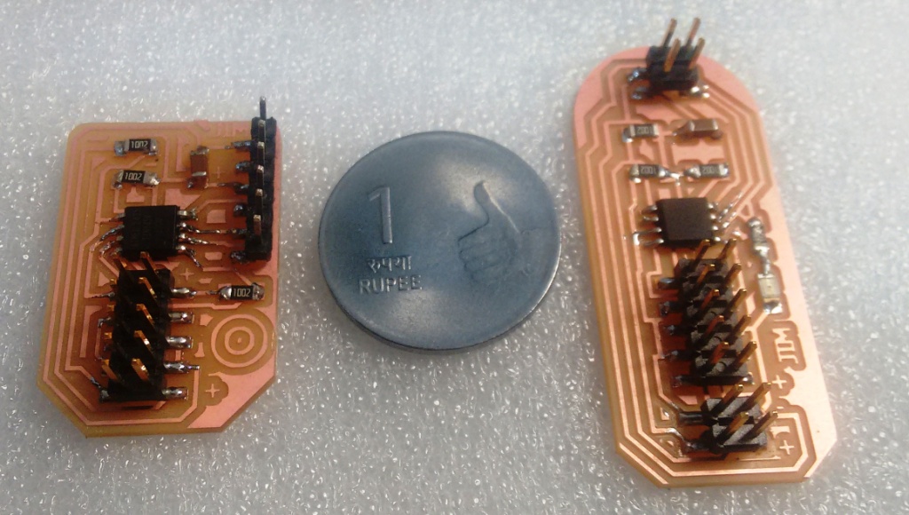
Making the Boards
I have milled and stuffed the boards using the modella. The photos of the boards are shown below.
Coding the Boards
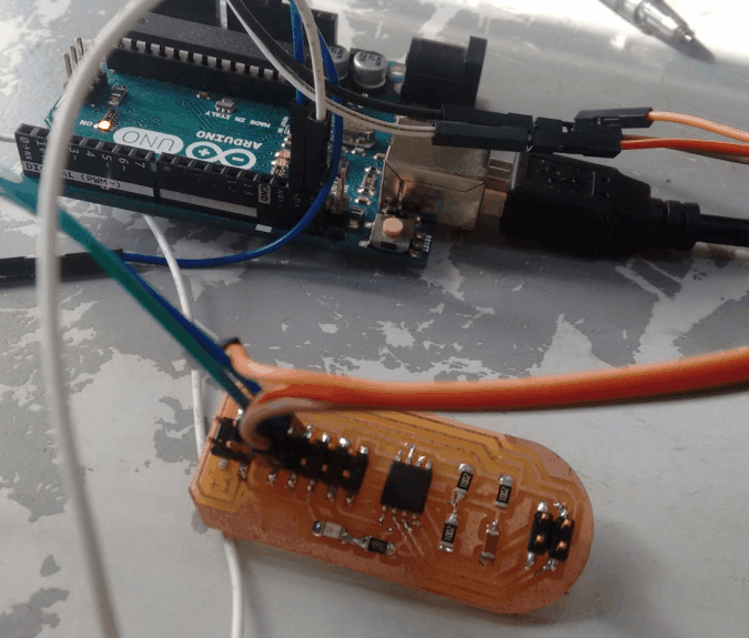
Try-1: Using Arduino as Master and Attiny45 as Slave
With the help of my fab mates, I have tried coding the boards using Arduino IDE. Initially I made the Arduino as the master and the board I have made as the slave(node). So upon receiving 1, the led on the node swithes ON. The code is available via this link.
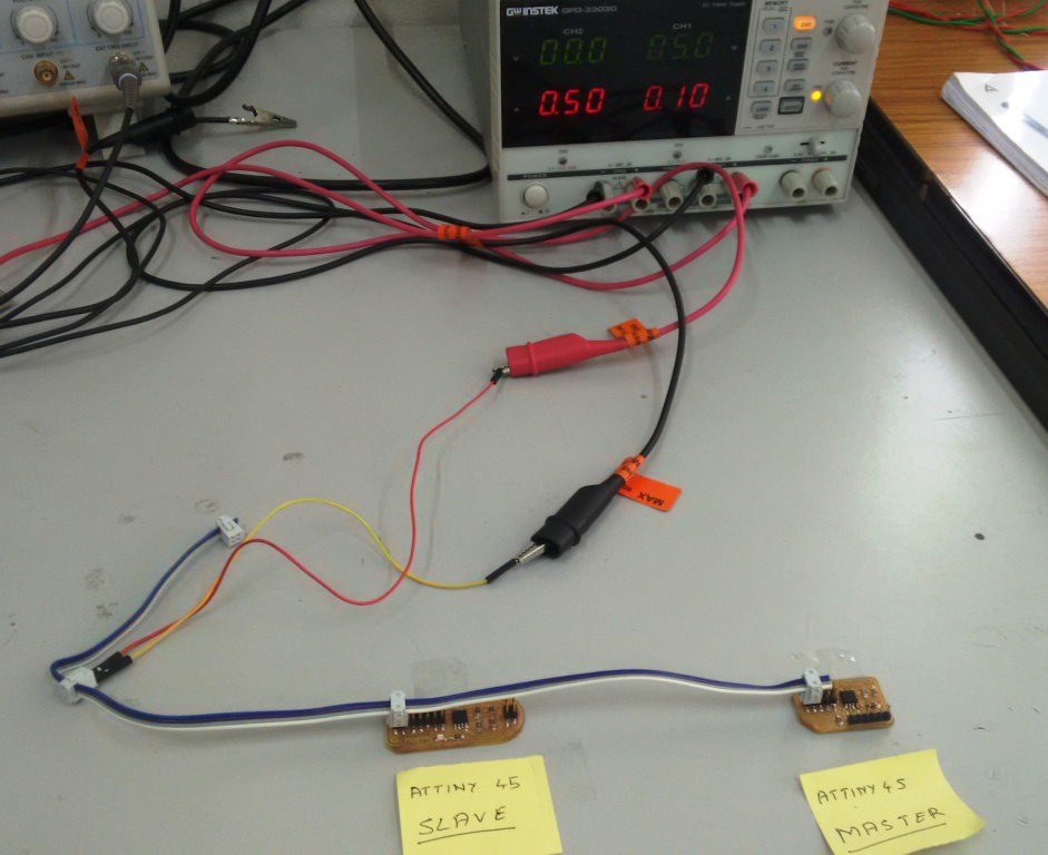
Try2: Using Attiny45 as Master and Attiny45 as Slave
Later I programmed the Attiny45 boards and master and slave. The testing using Attiny45 and the code used for this is illustrated below.
//I2C Code for Attiny45 as Master
#include < TinyWireM.h>
void setup()
{
TinyWireM.begin(); // join i2c bus (address optional for master)
}
byte x = 0;
void loop() {
TinyWireM.beginTransmission(0x4);
TinyWireM.write(++x % 2);
TinyWireM.endTransmission();
delay(1000);
}
In the above code the I2C is initialized in setup. And in the loop, transmission is started with address 0x4 (the slave attiny45) with an alternate 0 and 1.
//I2C Code for Attiny45 as Slave
#define LED_PIN 3
#define I2C_SLAVE_ADDRESS 0x4 // Address of the slave
#include < TinyWireS.h>
#include < avr/io.h>
#include < util/delay.h>
void setup()
{
pinMode(LED_PIN, OUTPUT);
TinyWireS.begin(I2C_SLAVE_ADDRESS); // join i2c network
}
void loop()
{
byte recd = 1;
if(TinyWireS.available()) {
recd = TinyWireS.receive();
if(recd == 1) {
digitalWrite(LED_PIN, HIGH);
delay(1000);
} else {
digitalWrite(LED_PIN, LOW);
delay(1000);
}
}
}
NoteFor having I2C on attiny45 we need to have two libraries TinyWireM and TinyWireS respectively.
In the above code the LED pin and I2C is initialized as slavewith address 0x4 in setup. And in the loop, transmission is received from master (alternating 0 and 1) and LED is turned ON when 1 is received and off when 0 is received from the master.
Conclusion
This week, I have learned the basics of embedded networking and commiunication and designed and build the boards to demonstrate the I2C communication protocol.
The Eagle design files for this week is available here.
The codes created as part of networking week's assignment is available here.