7. COMPUTER CONTROLLED MACHINING
Index
- Assignment
- Introduction
- The Concept
- Flexture Designing
- Initial Planning
- CAD Designing
- My Second Design
- Inspiration
- Cad Designing
- Final Rendering
- The Small Project Before the Big One
- Cad Designing
- Final Rendering
- CAM Modeling for shopbot
- Into the Big Machine
- Issues; They where all around
- Model Images
- Redesigning the Rocking Chair
- Final Rendering
- Flexture designing
- Its Show Time
- Summary
A. Assignment
- Make something big (on a CNC machine)
B. Introduction
This week we are working with ShopBot. The model we have here is ShopBot PRSalpha CNC . This a big machine and the biggest we have ever worked in the fab. This is a comparatively low cost CNC which can perform precision, large format, cutting, drilling, machining, and shaping in many materials like wood, acrylic etc and is controlled by a standard personal computer. The bed size of our machine is 96x48 inch.
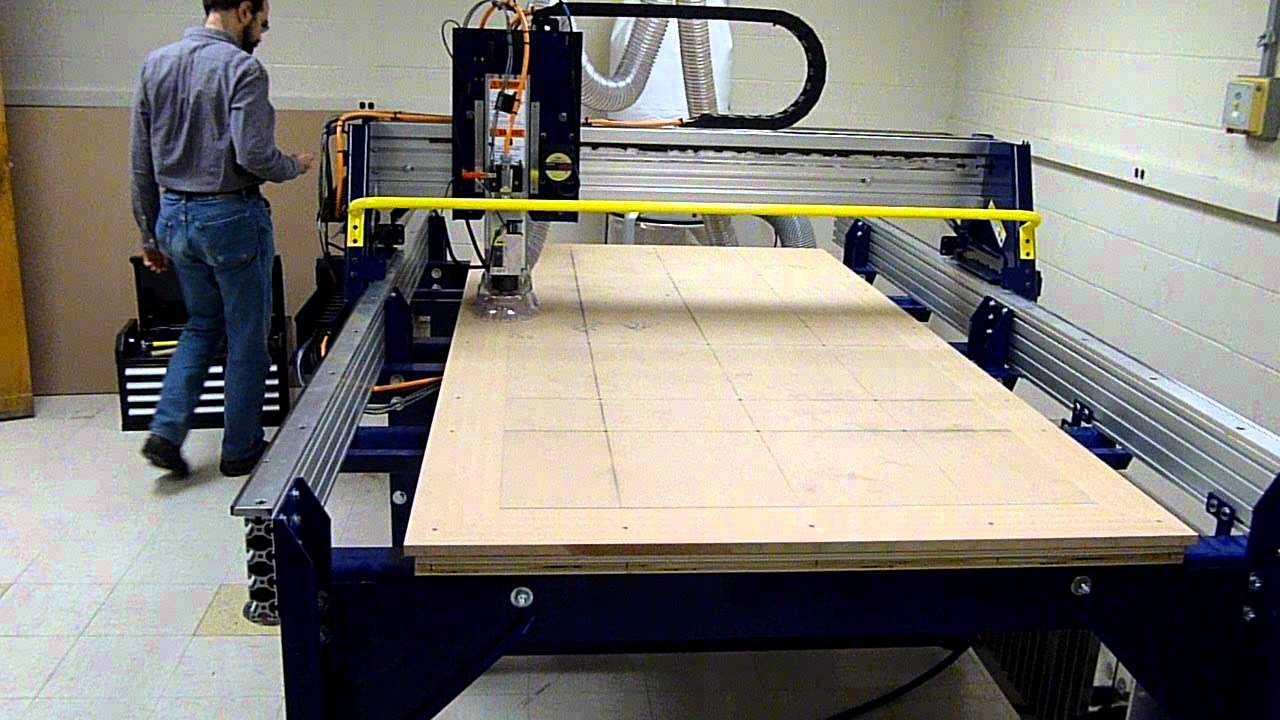
ShopBot PRSalpha CNC
More information about the Shopbot can be found here.
For setting up the machine refer to official shopbot
docs
For more details on feeds and speeds refer this document. This doc
will come
handy later when you are setting up a new tool in fussion for your project.
For more details on chiploads refer Detailed chip load
charts
C. The Concept
My idea was to make a a rocking chair with around 90 degree of rotation.
When you sit on a chair like that it moves to one side giving the feel of falling. This can help relieve
pressure
and tension. Thus it is an ultimate relaxing chair. As i want to give an ultimate relaxing experiance to
anyone using
my chair i wanted to make the sitting surface with a flexible material so that it gives a more
cussioning
effect on the back. As there wasn't anything in our lab which was suited for the purpose, i plan to make
plywood
flexible and use it as the sitting portion of my chair. I also put a backup design with the flexible
plywood replaced
with plywood rails, so that i have something even if my fluxure does't work.
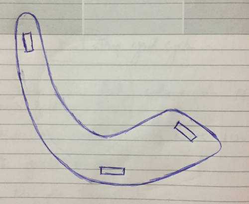
Initial drawing
c1. Fluxure designing
My initial idea of the fluxure was inspired from an origami which we use to make in our
shool days.
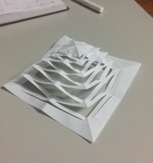
Origami inspiration for flexible plywood structures
You can see that this kind of a design gives only a belly kind of flexure. This looks cool, maybe i can
use it for something
else, but it is not enough for my rocking chair. So i tried extending this design and see if i can get
the required results.

Extended design
I made 4 similar structures in a paper and tested out the flexibility. The structure was flexible but
was not what i wanted.
I started to search the web more intensively for what i want and finally found a couple of things which
i can use for my design.
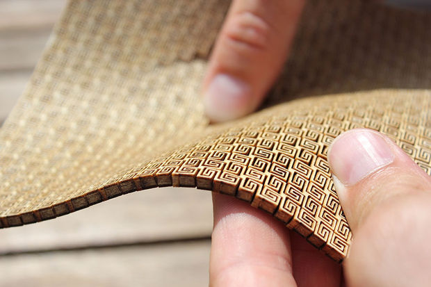
Flexure from instructables

Flexure from msraynsford.blogspot.in
Another design from the internet
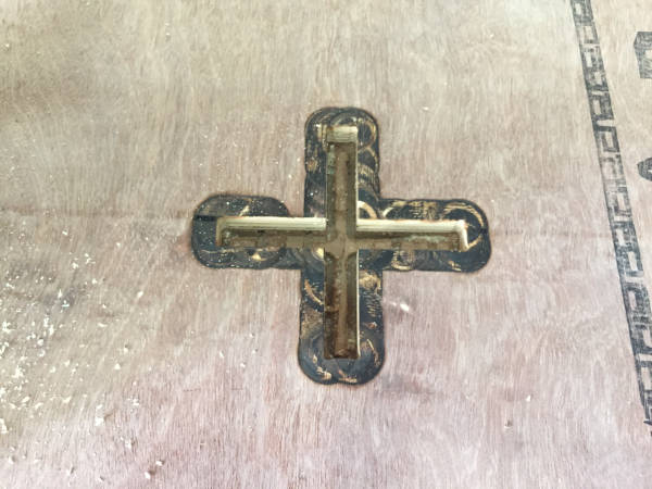
I recreated the first two designs in craft wood and the following are the results.

My re-creation of flexible plywood - design 1.
This design has less flexiblity but is more stable and less brittle.

My re-creation of flexible plywood - design 2.
This design is more flexible but is brittle.
So i have decided to use the first design on my project as it is more stable, considering
the fact that plywood is less stronger than craftwood.
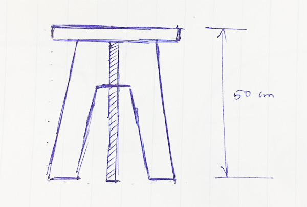
d. Initial planning
I need to find a possible diamension for my chair. My friend Syed Ahamed helped me with this.
he lied on the floor so that i could measure out the length and width for the chair. The length was
estimated to be 130 cm, width 100 cm and height 110 cm.

Identifying measurements for the chair.
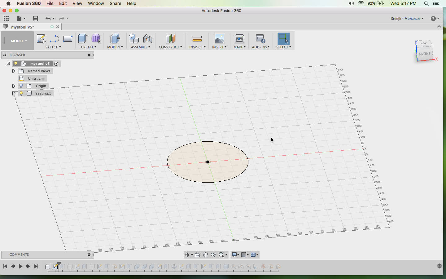
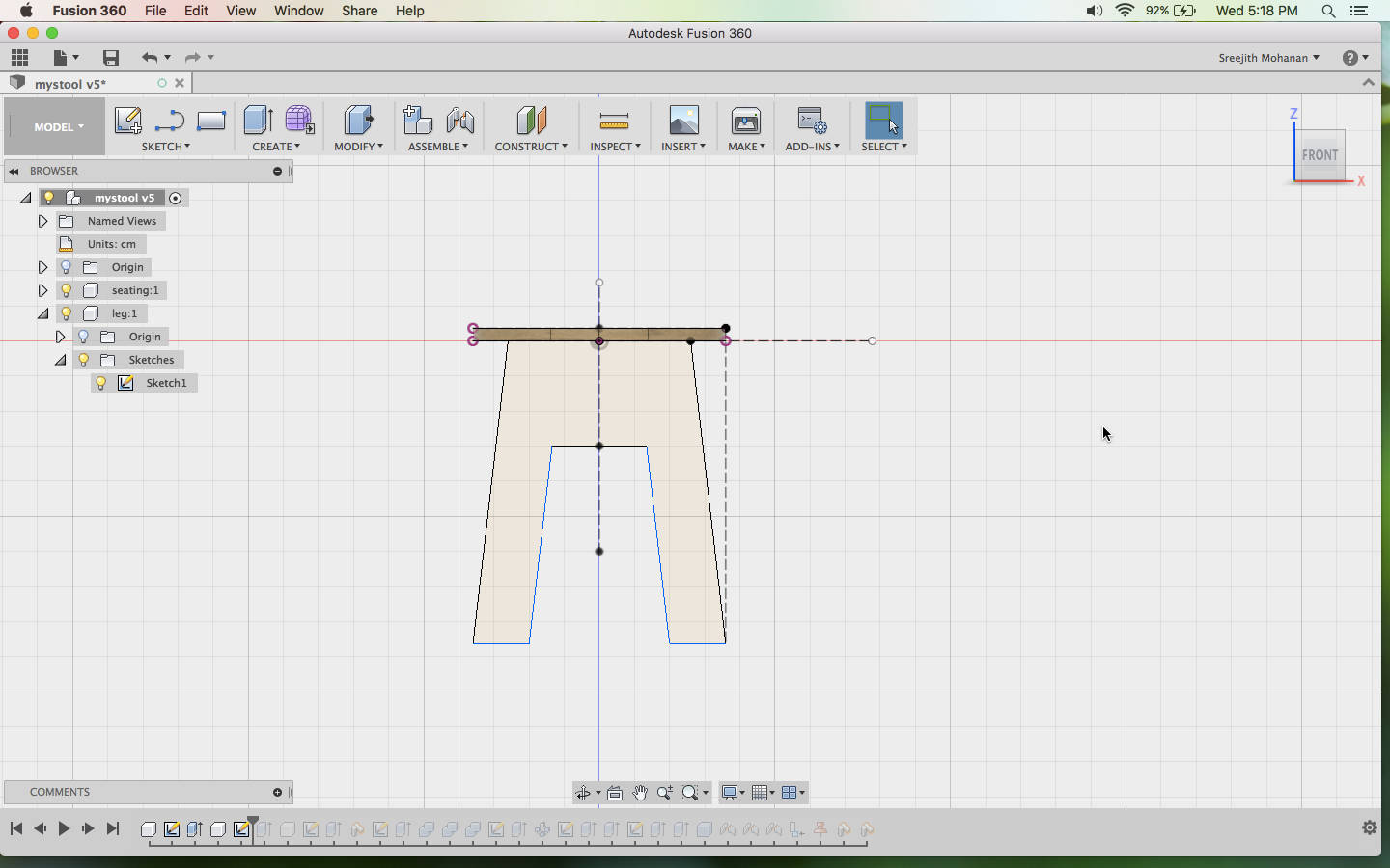
e. CAD Designing
As always i am using Fussion 360 for my designing. The steps are Documented below. My major issue while designing was that i had to make sure that my single design has room for the actual dsign and for the backup design. Also it was not possible(to my knolwdge) to show the flexure in the tool also. So my plan was to design with the rails first and if the flexure was forming properly i will cut away the slots for the rails and fix in the flexure else i will go with the rails itself.
- I made a drawing of the side of my chair in photoshop for clarity
purpose

Drawing in photoshop - Now using the above image as reference, i started making the
sketches in fussion.

The basic sketch - now i started creating the dogbone structures for better fit..

Dogbones - Now i extruded the sketch and made a copy of the body to make both
sides of the chair.
Sides of the chair. - Then the inner connecting pieces where made from the sketch
Basic chair structure.
- Now the slots for fitting the rails where made using a sketch and extruding it to
create a cut.
Slots for fixing the rails. - Finally i created the rails by extruding the sketch and patterning
it..
Final structure - Now a woody material was added for better visuals

Material added - Arrange the parts flat on a piece of plywood.
Flat packed model.
Final Rendering
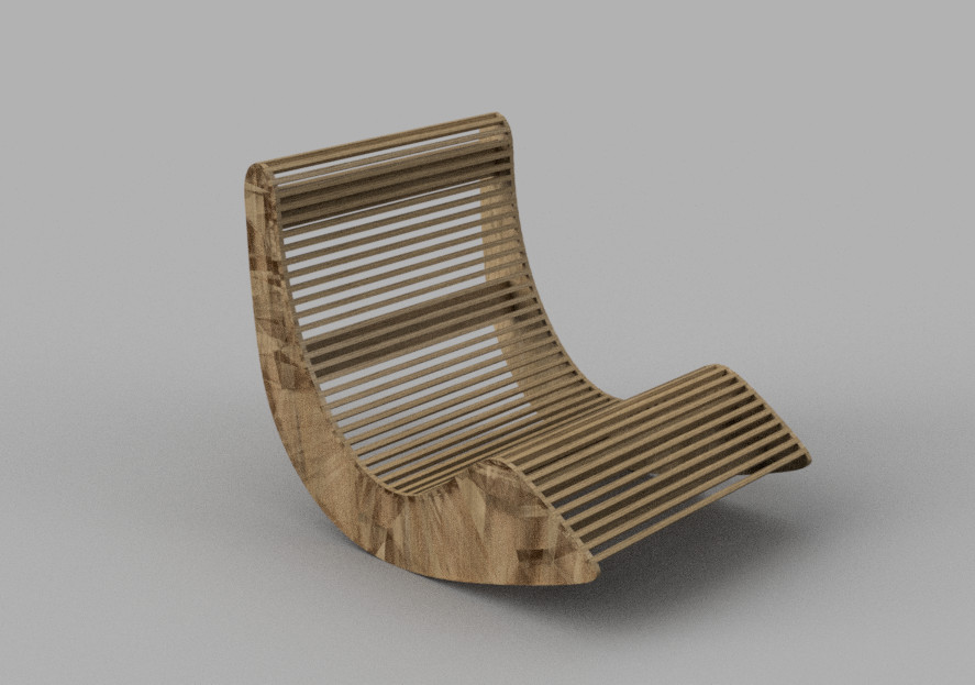
Final rendering
Original fussion file
As i finished my designing i understood that this is a big project and as i have no prior experience in doing it i should try something small before attempting one this big.
f. My Second Design
f1. Inspiration
This is a work from pinterest which i found interesting.
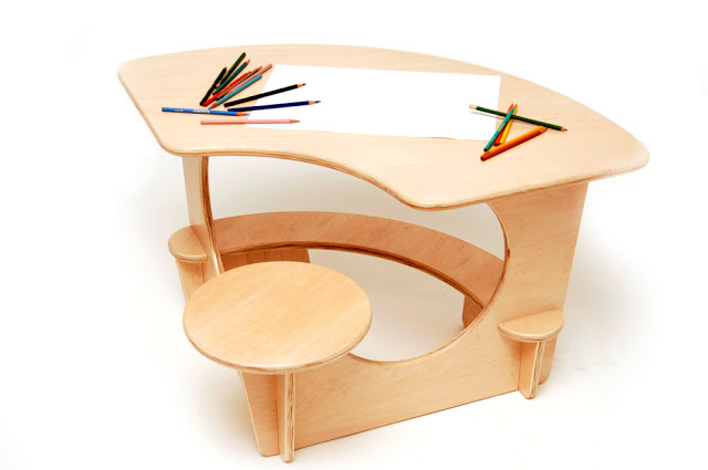
learning table-chair set.
f2. CAD Designing
As always i am using Fussion 360 for my designing. The steps are Documented below.
- I made a basic drawing

Drawing the sketches - First i made the sketches as in the image below

Drawing the sketches - Extrude out the profiles to generate the shapes.

Extruding the sketches - Now you can create the sketches for the side pieces

Sketch for the side piece - Then extrude the side part and create a copy of it and rotate it
to 90 degrees.
Finally use the combine tool and generate the pockets for the model

Sides of the chair. - Finish of the model

Final model.
f3. Final Rendering
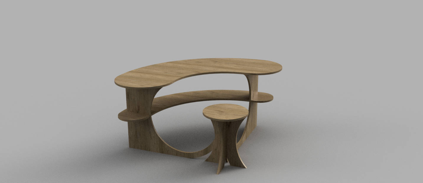
Final rendering
Original fussion file
This model is also quite big and i want to done something still smaller as a start so i am moving on with something else
g. The small project before the big one
Shopbot is the biggest machine so far i have ever dealt with so as this
is my first try i will do something small.
The following is the model for a chair i am making.
A simple press fit chair.
g1. CAD Designing
Again i am using fussion 360 and you can find the steps below.
- First i made the sketches for the sitting base as in the image
below
Drawing the sketches - Now you can create the sketches for the side pieces
Sketch for the side piece - Extrude out the profiles to generate the shapes.

Extruding the sketches - Create the press fit joints and dogbone structures

Sides of the chair. - Finish of the model
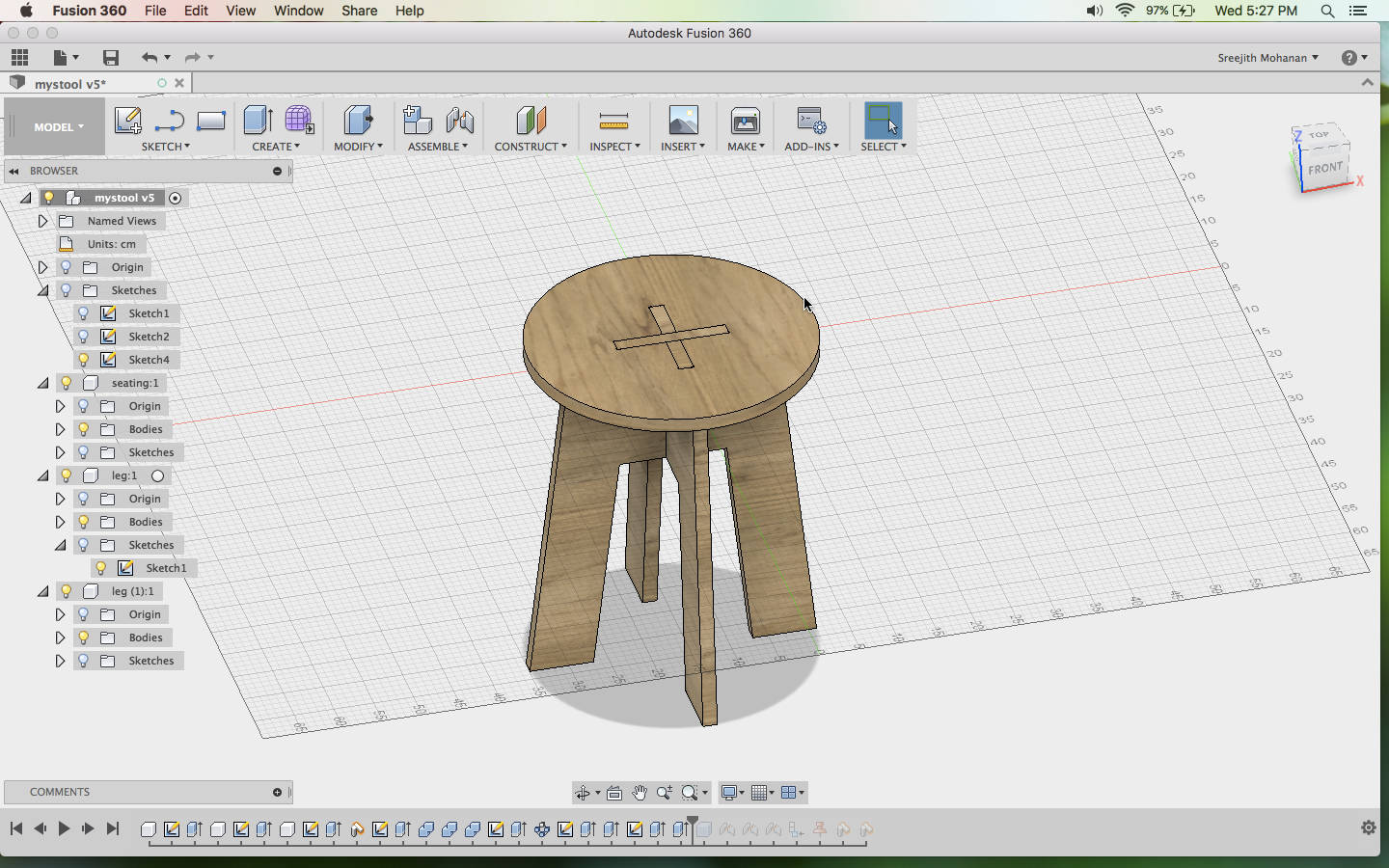
Final model.
g2. Final Rendering
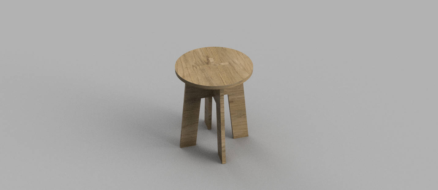
Final rendering
Original fussion file
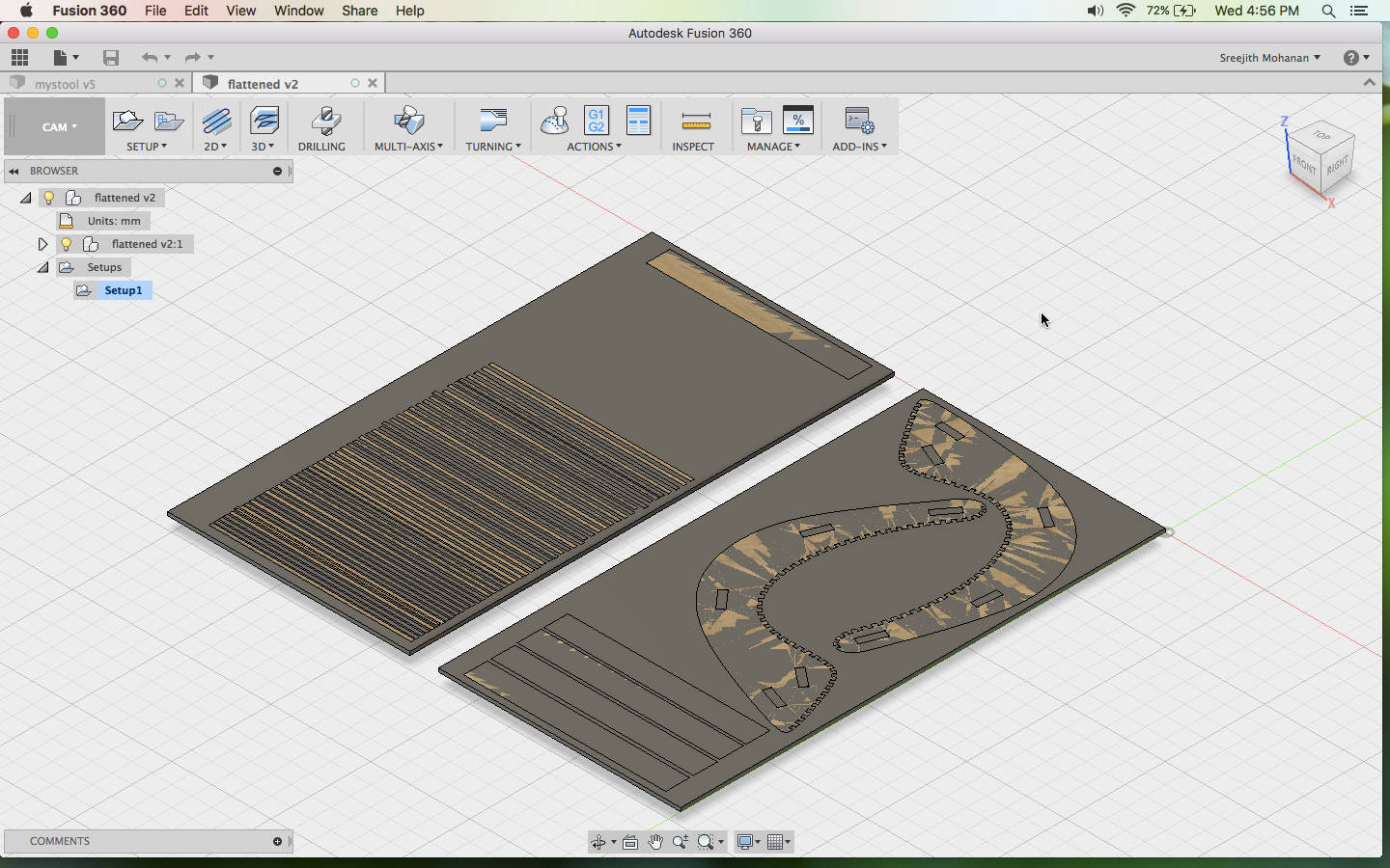
g3. CAM Modeling for shopbot
In our lab we were using VCarve for generating the shopbot files. We have never tried anything else. As i have done the CAD in fussion and as fussion has a full fledged CAM environment i decided to do the CAM in fussion itself. This is a trial and error process and i am documenting the process below.
- First thing to do after completing the designing is to convert all
your
model to components. Now create a box with exactly the ply size you are planning to use and create
planar joints of the
model parts in the box created. This will create a flatpack of our model in the box. You can see
this in the image below
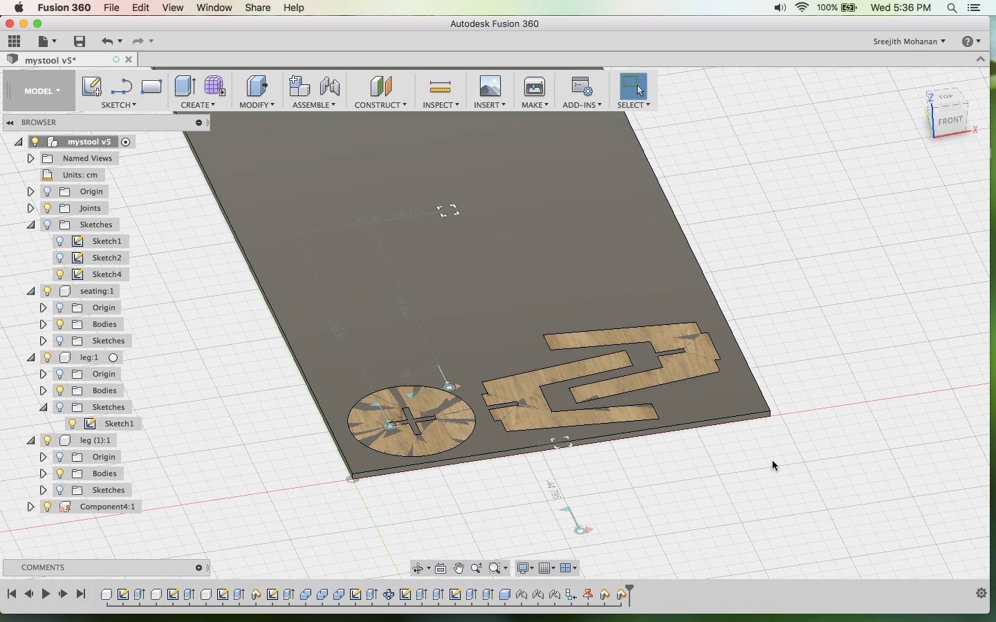
Parts of the chair arranged in the stock plywoodWhile adding joints between the stock and the model parts make sure that you make the joints as 'planar' type. This will allow you to move the parts within the stock and place it anywhere you want, reducing space wastage.
- Now you can switch into the CAM workspace in fussion 360 and
create a new setup and add the
following settings

Basic setupThis panel contains the coodinate system settings. Remember that the shopbot sets it origin at the bottom-right and x axis is is vertically up and y axis is horizantally left so you need to set the codinates of our model also to be aligned with this. Here you can also select the parts you want to print. Only the selected parts will get cut.
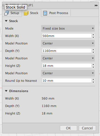
Stock settingsStock basically means the wood size in which you want to cut out your parts. The default will the size just enough to cut out your models. There is no need to add and padding if you are setting the zero of the machine properly. Set the height to the plywood thickness and make sure that the mode is 'Fixed size box'. You can see the dismensions below, now make sure that the plywood you are planning to cut has these diamensions.
- Now we need to create a tool for our operaion.There are many
default tools
available in the library within the fussion software but i would prefer to create a custon bit for
my operation. To do this
click your name on the top right and choose preferences.
Now from CAM >> check to enable. the cloud tools option
Create a new toolset with a name you want and a new tool with the following settings
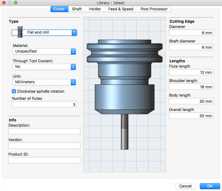
Cutter basic settingsHere the tool diameter is the the most important one. You can fill this up by either refering to the bit manufactures specifications or by measurng the bit or from the above listed docs. I got the data from the docs. Flute- this is the part of the drill bit which has that engraving. More details about flute and other parts of the machine can be found in the shopbot doc
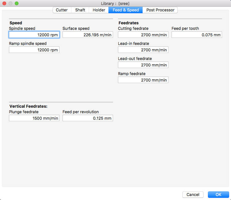
Feed and speed settingsYou can neglect the shaft and holder settings as they wont affect the cutting. But if you want perfect simulation in fussion setting them can help. The next importent settinga are the feed and speed. I have copied this settings from the Vcarve settings which was already being configured for the bit. You can find them here in the image.
Spindle speed is the speed of the spindle. Ramp spindle speed is the speed of the spindle while making helical cutting operaion into the material. Surface speed is the speed of cutting. Cutting Feedrate is the feed used in cutting moves. Feed per Tooth is the cutting feedrate expressed as the feed per tooth. Other feed rates can be set as same as the cuting feed rate.
Plunge feedrate is the speed of drilling down vertically, ie how much depth is drilled in a minute. You can leave the post processing tab with the default settings. - Once you are done with the setup you can go ahead and create the
cutting operations. I am using only the cutting operation and not the pockets. For cutting you need
to use 2d contours.
Create a 2d countour from the 2d dropdown. Choose the following settings
This link has all the documentaions about all these settings.
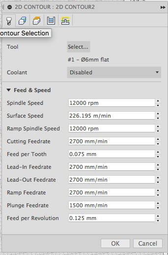
Tools settingsThe only thing you need to do on this panel is to select the tool which we have already created. This will automatically update all the required settings in this panel. Cloose coolent disabled.
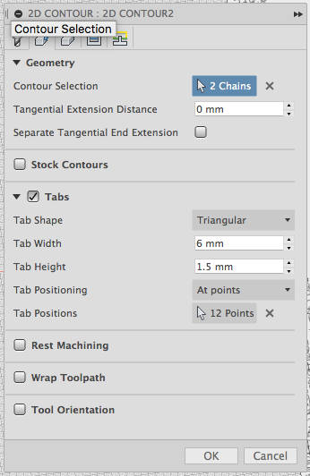
Geometry settingsHere you can choose the geometries to be cut, make sure that you choose the bottom curves else the machine will cut in the air. Also make sure that the arrow is outside the shape meaning outer cut. If the arrow shows from inside to outer it means inner cut. Simply click on the arrow to toggle this.
If you want tabs you can do that here. The settings i used are shown below. Here i have used manual placing of tabs, you can choose to put tabs at particular distance if you want.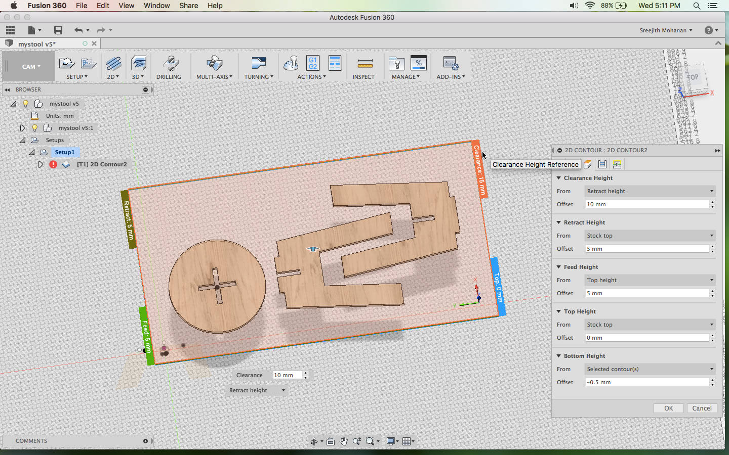
Height settingsThe default is okey except the bottom height. This i like setting to 0.5mm from the bottom of the stock to ensure that the pieces are properly cut out. Remember that all the heights are set relative to some other thing.
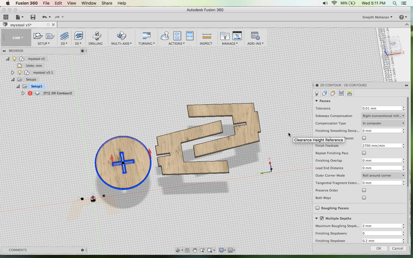
Passes.See the red arrows here? for the + shape it is inner cut, so arrow pointing from inside to outside and the outer cutting , we have the arrow on the outside meaning outer cut. Here i change the sideways compensation to right conventional milling and enable multiple depths and put the depth(max stepdown) to 3mm so that cutting happens in steps of 3mm each. For other settings the default is fine
- You can simulate your model for ensuring results, you can either
choose the setup as whole to see
the whole cutting , pocketing operations at once or just select one operation to see that alone.
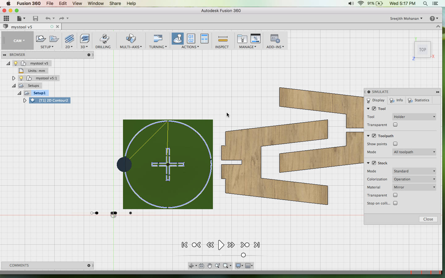
Simulaiton of the cutting operation.Here i have just choosen the circular part and simulated that alone. You can see the tabs and the cuts and the movement of the head. This is a nice way to inspect the cutting operations before it is being done. You can fix a lot of errors in your job by looking at this.
- Once you are satisfied with the simulations and verified all the
settings you can generate the
shopbot files. To do that
Choose post processing from the actions tab or click on the G1 G2 icon. This will open up a panel from where you can choose the export format to shopbot.cps- Open shopbotSBP format and save the file. Other settings will go with the default.
Remenber that you can generate files for a process by selecting that alone or the whole processes at once by selecting the setting in the tree. - Put on the safety gloves and the googles
- Now set the plywood in the bed and fix it tightly with screws.
- Put in the correct drill bits. Refer doc
- Now set the zero of the machine using the interface. Refer doc if you need assistance.
- Now you can load the stp file generated in the previous step into the shopbot control interface and fire up the machine to make the cuts.
g4. Into the big machine.
Before moving onto the machine make sure that you have read the second and third documents listed in the begining throughly and make sure to follow all the safety measures.
g5. Issues; they were all around.
- The first issue i faced was that when it came to cut out the seating in the chair, the
model went outside.
Cut going outside.This happend because i didnt place the zero of the machine in a place that the machine has enough room to cut everything. I didnt verify that the distance from the zero is enough for my model. Now i had to cut the seating again.
- This time i messed up with picking the tool and took some other tool in my cam
controls.
Plywood burned outPlywood burned out due to the collet rubbing over the ply. The tool i selected was having a grater cutting depth than 18 mm so the bit went so deep that the collet started rubbing over the ply.
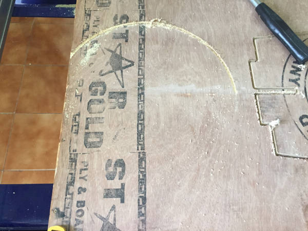
g6. Model Image
Cutting out
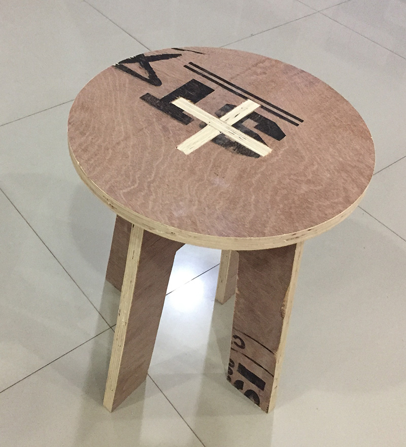
Model printed and fitted
Original fussion file
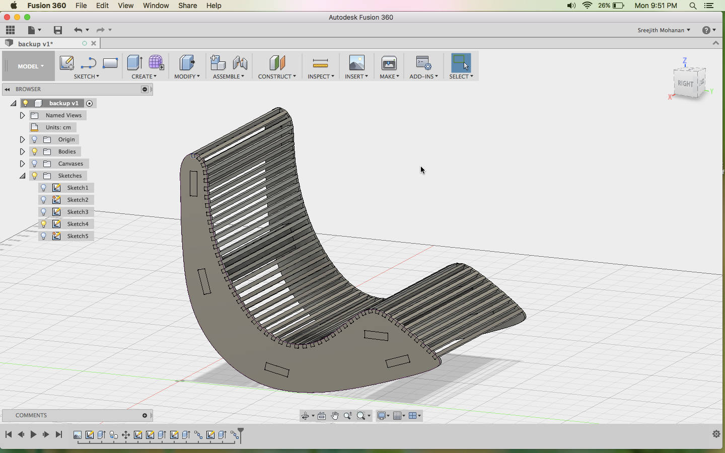
h. Re-designing the rocking chair
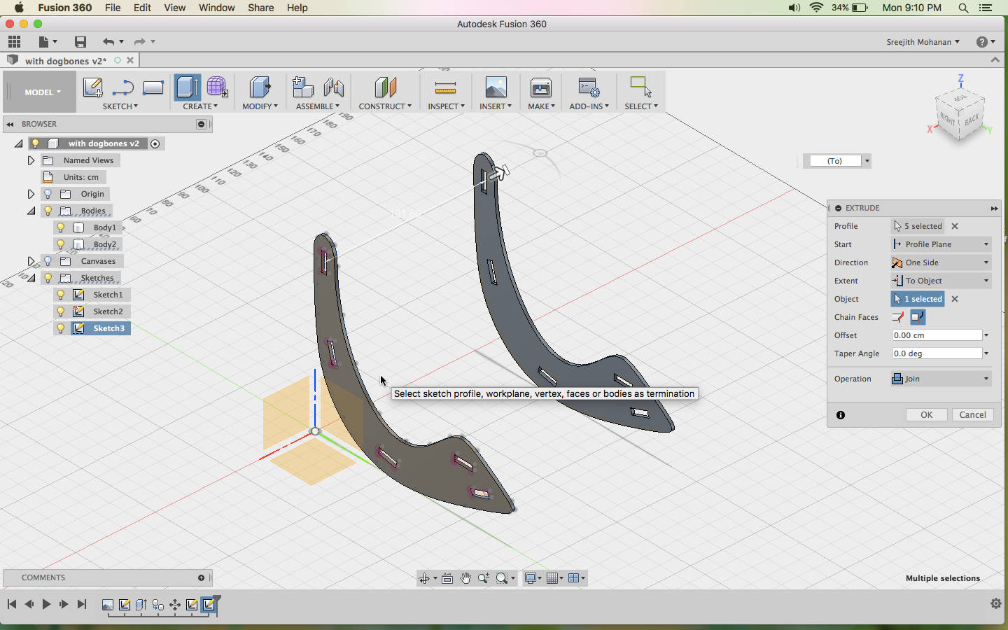
Now once i have tested fussion 360 cam and i have made this small chair i think it is time to go ahead with the first model i started with. After making the chair i realize that the plywood i was using was not hard enough to hold much weight. So if i use the same material to make the rocking chair which need to support the weight of a person, It will breakdown. I decided to redesign the model with more crossbars to make it more stable. I also does not want to use any nails to hold the parts together. I decided to use the press fit alone.
- Starting with the basic design of the side parts from the previous
design
Reusing the side parts from earlier design - Now start creating the side connecting parts. To do this you can
first draw the profile
on the side part and then extrude it out till the other end part. On the parts where the body will
on the side part and then extrude it out till the other end part. On the parts where the body will
rest i used the arc tool to get the curvature.
This type of structures where created by creating a construction plain and then creating the shape
and extruding it out.
Creating the inter connections - Later i added semicircle end to all the interconnections to make
the parts more strong. Then i created the slots for press fit, also
added the dogbone fillet for proper fitting.

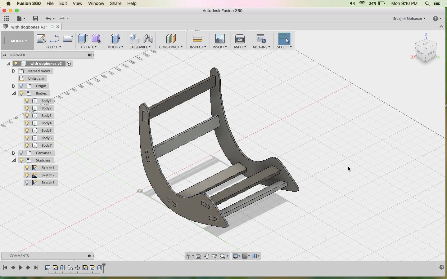
Slots for pressfit - Finally i flat packed the parts and prepared to cut. I used the
same CAM settings in
my stool example excapt for the feed size. You can see that one part doesnt fit to the ply and need
to be cut seperately.
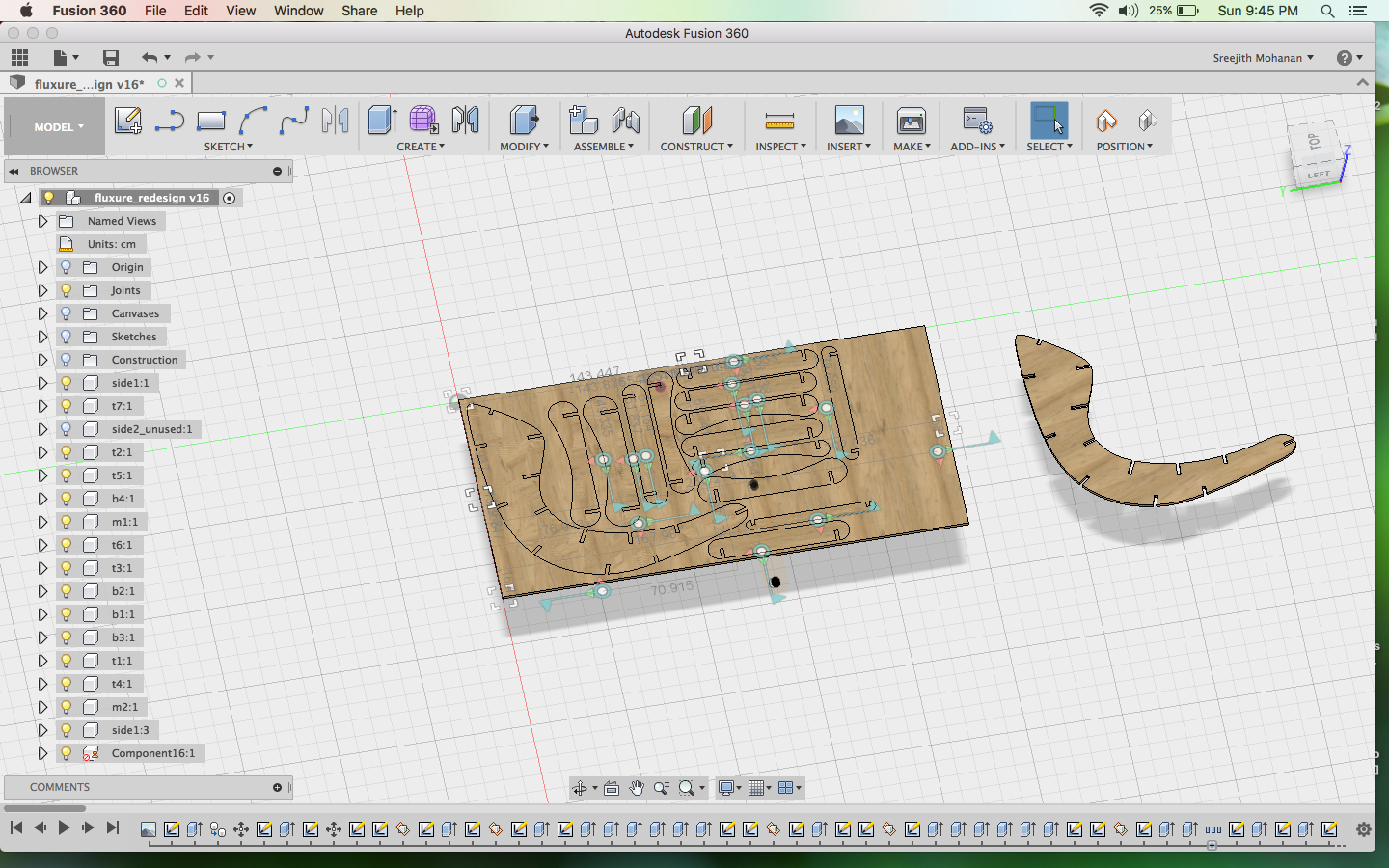
Sides of the chair. -
Finally i cut out the design in 18 mm plywood an fitted the parts.
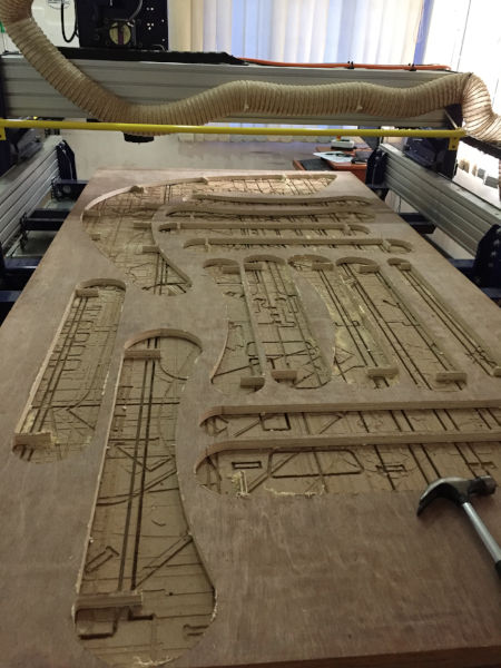
Cutting out
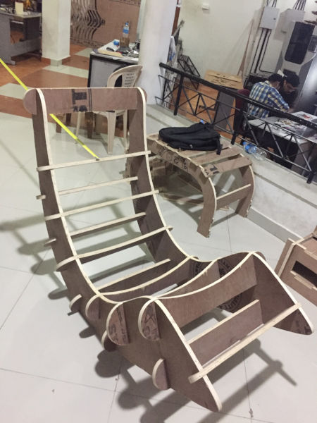
Model cut and fitted
-
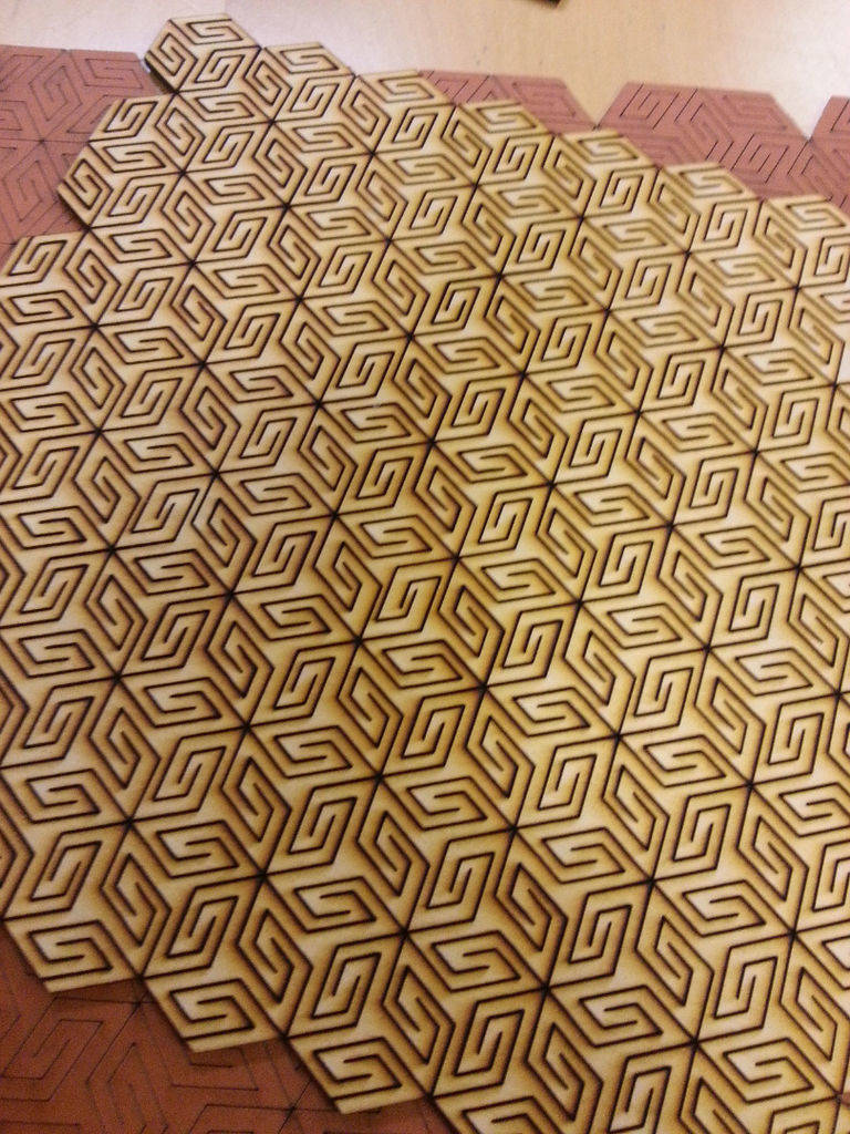
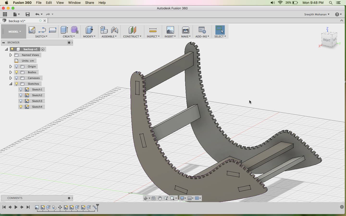
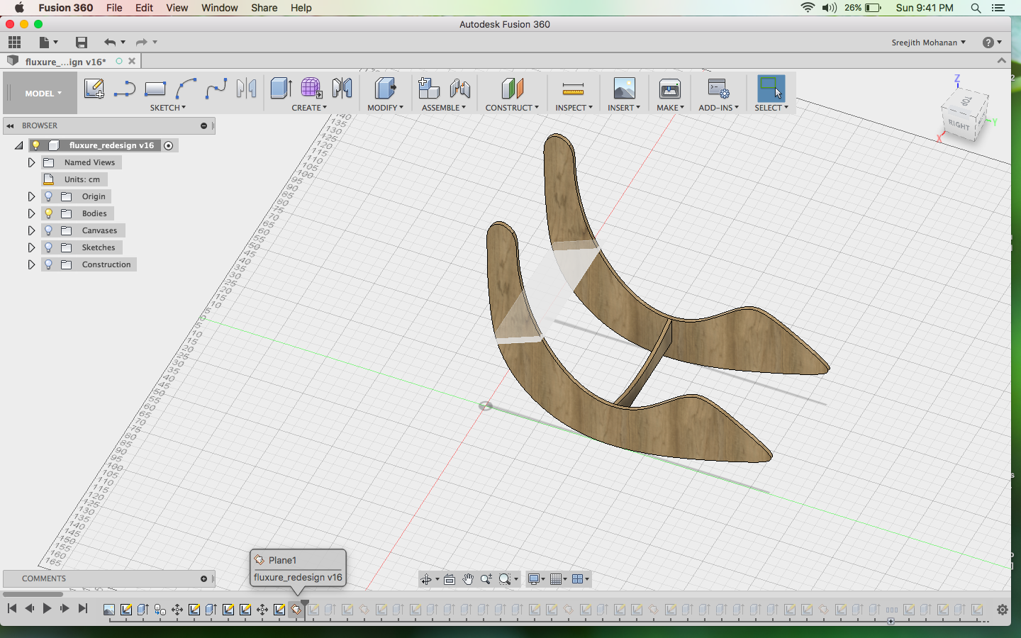
Now i had to make the flexture design.
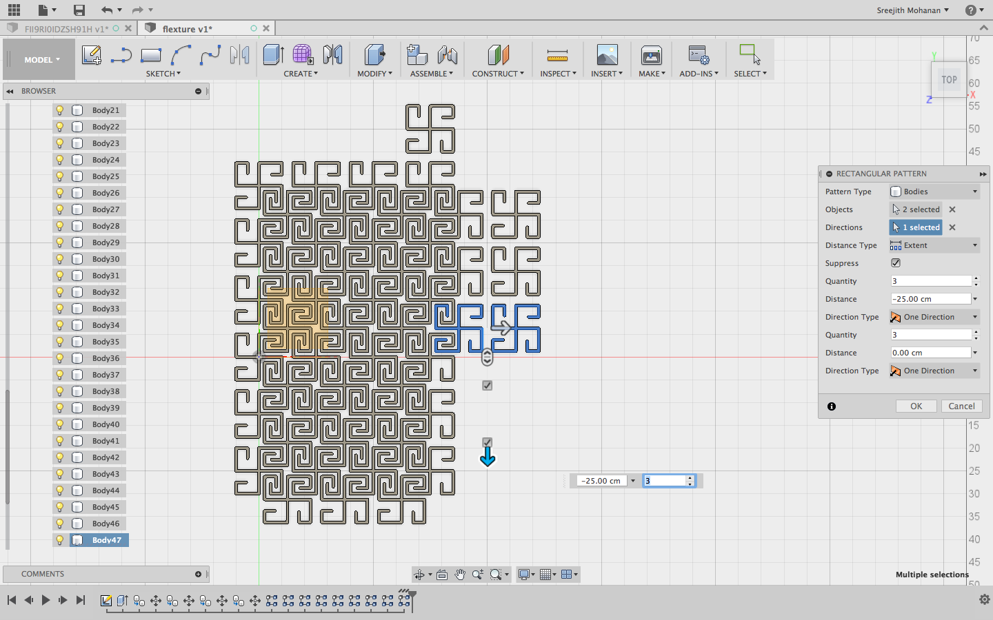
Designing the flexture
Designing the flexture
Original fussion file -
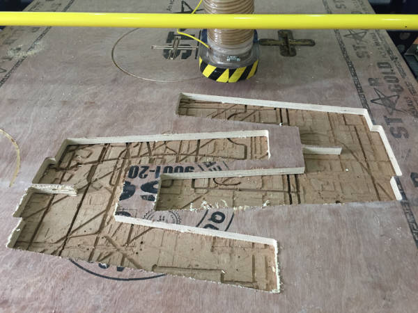
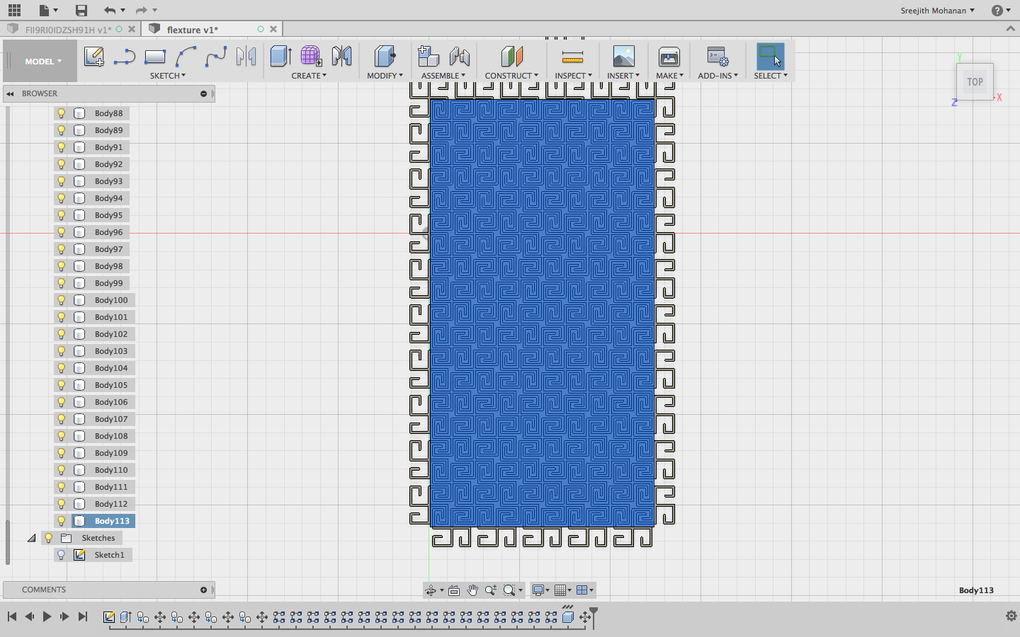
Finally i cut the flexture out in a 12 mm plywood.
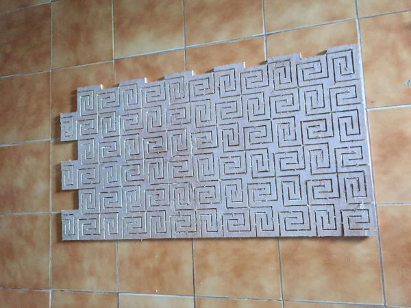
Flexture cut out
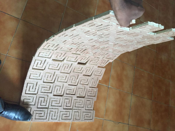
Flexture blending
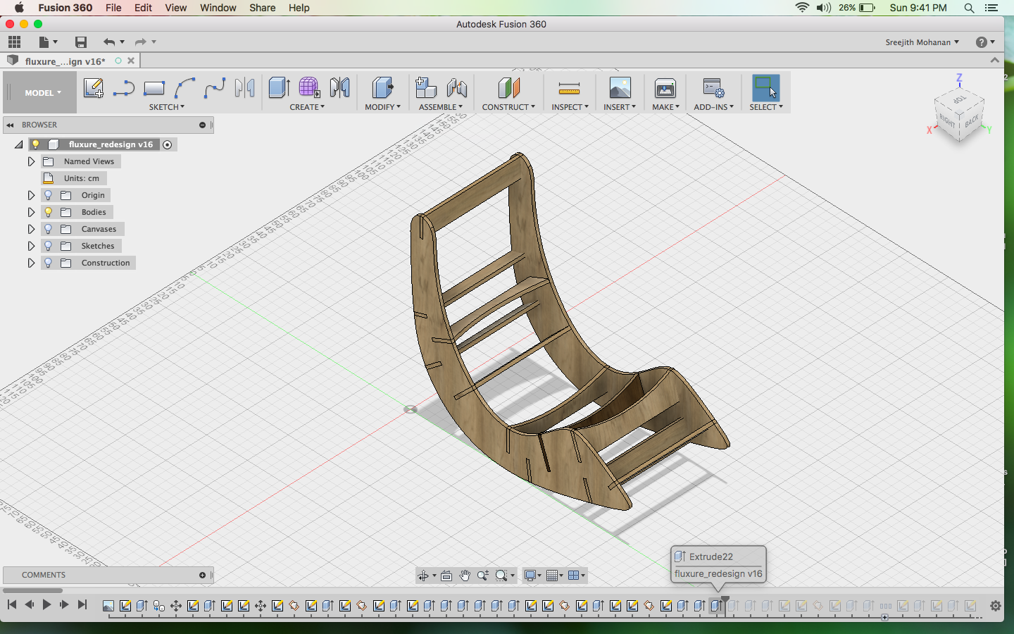
h1. Final Rendering
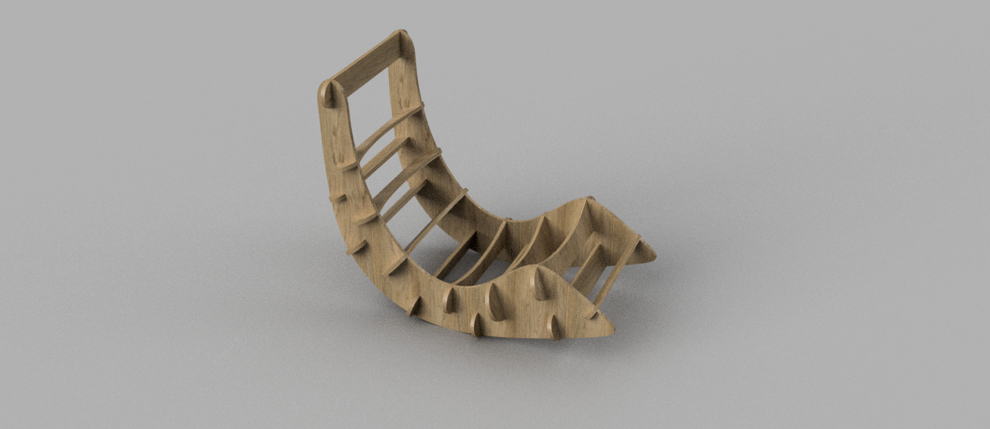
Final rendering
Cad model 3d
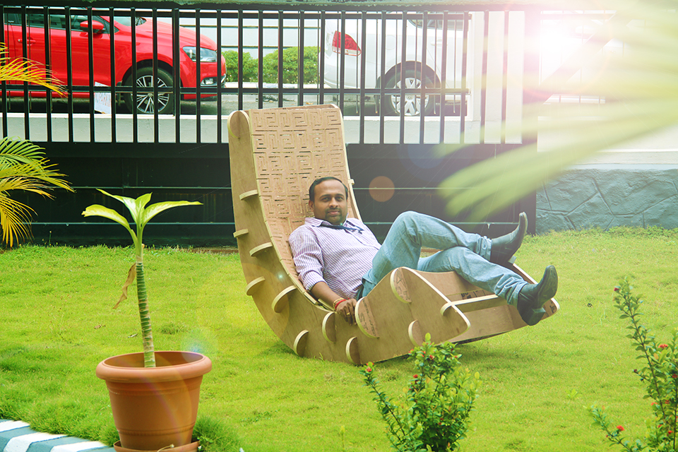
i. Its show time again

Original fussion file
J. Summary
- Learned to handle the Shopbot.
- Designed and made couple of furniture's with shopbot, componsating for allowance and dogbone fillets
- Experimented with the CAM functionalities in fussion 360 and learned to use them
- Experimented with flextures and their potential applications.

This work is licensed under a Creative Commons Attribution-NonCommercial-ShareAlike 4.0 International License.