14. COMPOSITES
Index
- Assignment
- Introduction
- Making the CAD model
- Generating the tool path
- Making the model in shopbot
- Cutting the fabric
- Making the composite
- Results
- Summary
A. Assignment
- Read the material safety data sheet (MSDS) and technical data sheet (TDS) for the resins that you're using.
- Design and make a 3D mould (~ft2 /30x30cm), and produce a fibre composite part in it.
B. Introduction
This week we are working with composites. As the name suggest composites consists of two or more materials. We combine them to for a strong material. The properties of the combination will be much better than the material alone. Today composites are used in places where metal was previously. The advantage of composites is that they are equally strong as the metal but is much lighter and is often cheap to manufacture. Composites usualy have a fibrous material bounded tightly by another material called matrix.The matrix binds the fiber together while the fiber gives the mechanical strength and stiffness. The fibers commonly used are glass, carbon, silicon carbide, asbestos etc. The matrix is usually plastic, metal, or a ceramic material. We use epoxy as matrix, burlap and cotton lint cloth as the fiber. I plan to make a fan blades this week
c. Making the CAD model
I used fussion 360 to do the modelling. The following is the model i made.
CAD model
Download the model
d. Generating the toolpaths
The model made with fussion was exported as stl file. We use Partworks software to generate the toolpath and the stp file which can be used in the shopbot for carving the model.The following is the step by step procedure of using partworks to generate the stp file.
-
Open partworks software and open the stl file in the software. You will be taken to step 1 of
toolpath
generation as shown in the screenshot below. This is the stage to set the Model orientation and
size.
The diamensions of the model will be automatically set. Make sure to make select top surface
to be top in the first section. Once you are satisfied with other settings, click next.
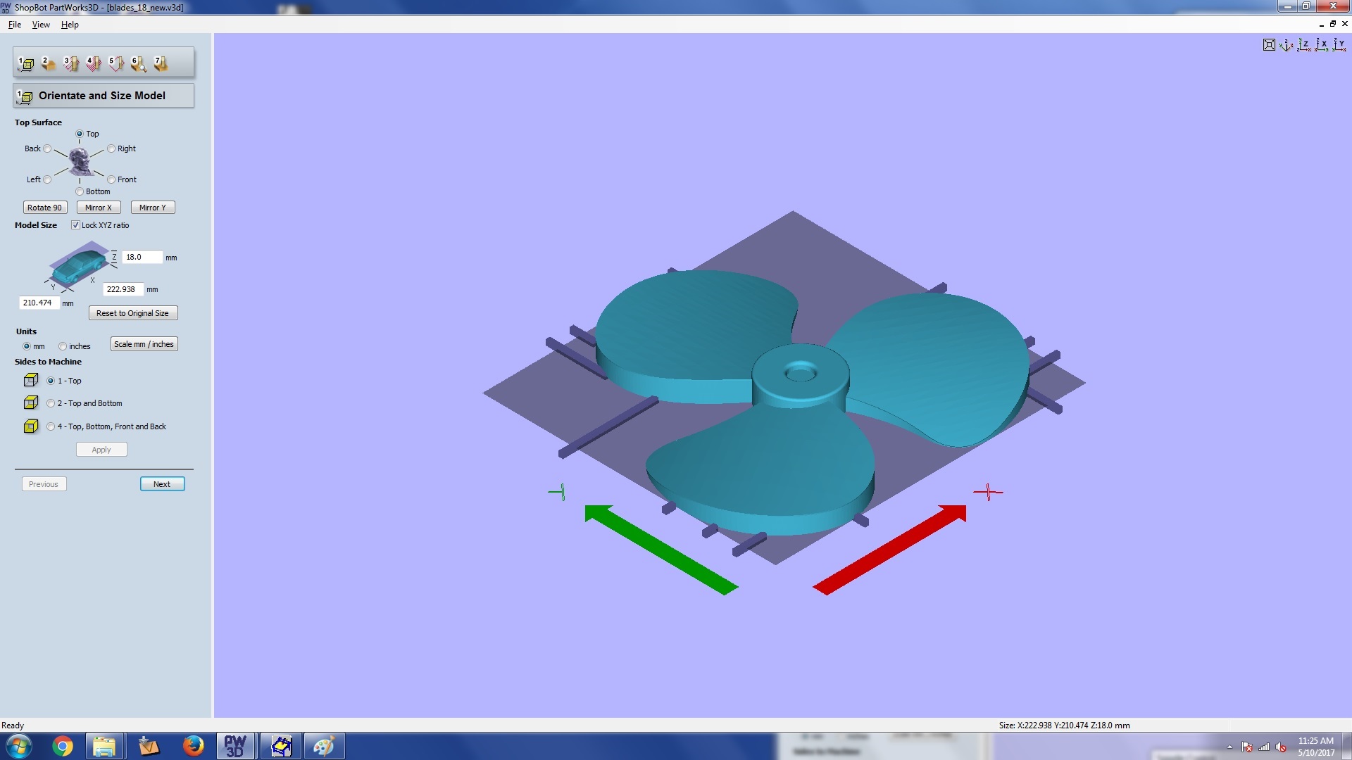
step 1: model orientation and size
-
THis is material size and margins section. Here we can set our stock size. and the origin.
We use bottom right as our origin for shopbot. Make sure to set zero on the top plane.
If you want to give some extra depth for properly cutting out the model then do it in the cut plane
position in model section. You can give something like a .5 mm extra depth from the bottom. Now
click next.
Here you have the option to add tabs to the model Use that if necessory. I have used a few tabs to
make sure
that the model stays to the stock after cutting.
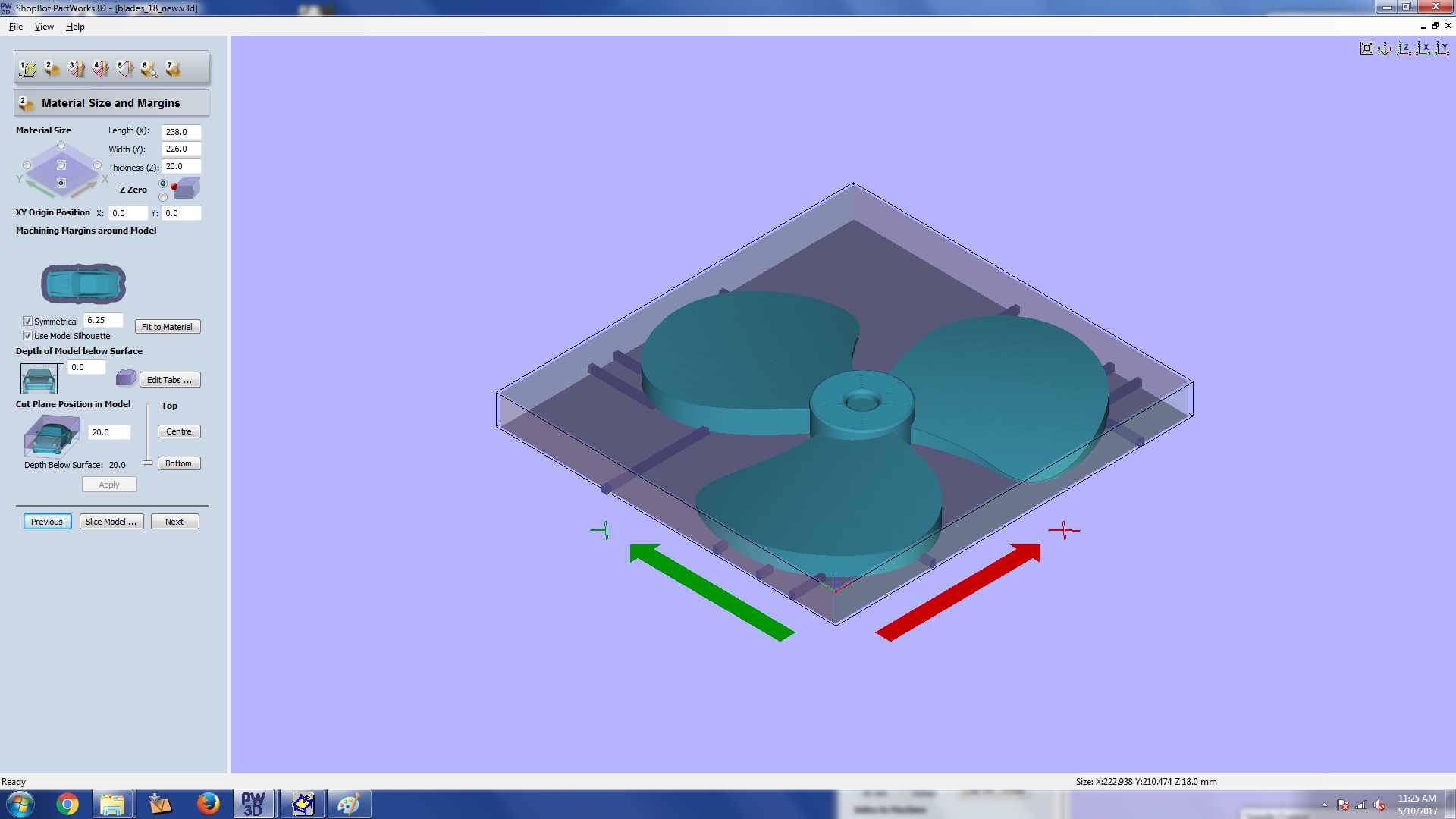
Step 3: material size and margins
-
This is roughing toolpath section. Here you can select bit and settings for your roughing
opereation.
Spindle speed, feed rate etc can be provided. You can look through the values i used. Once you are
done clink calculate
before moving on to the next section. This will generate the tool paths for you. Remember to click
the
calculate button every time you make changes.
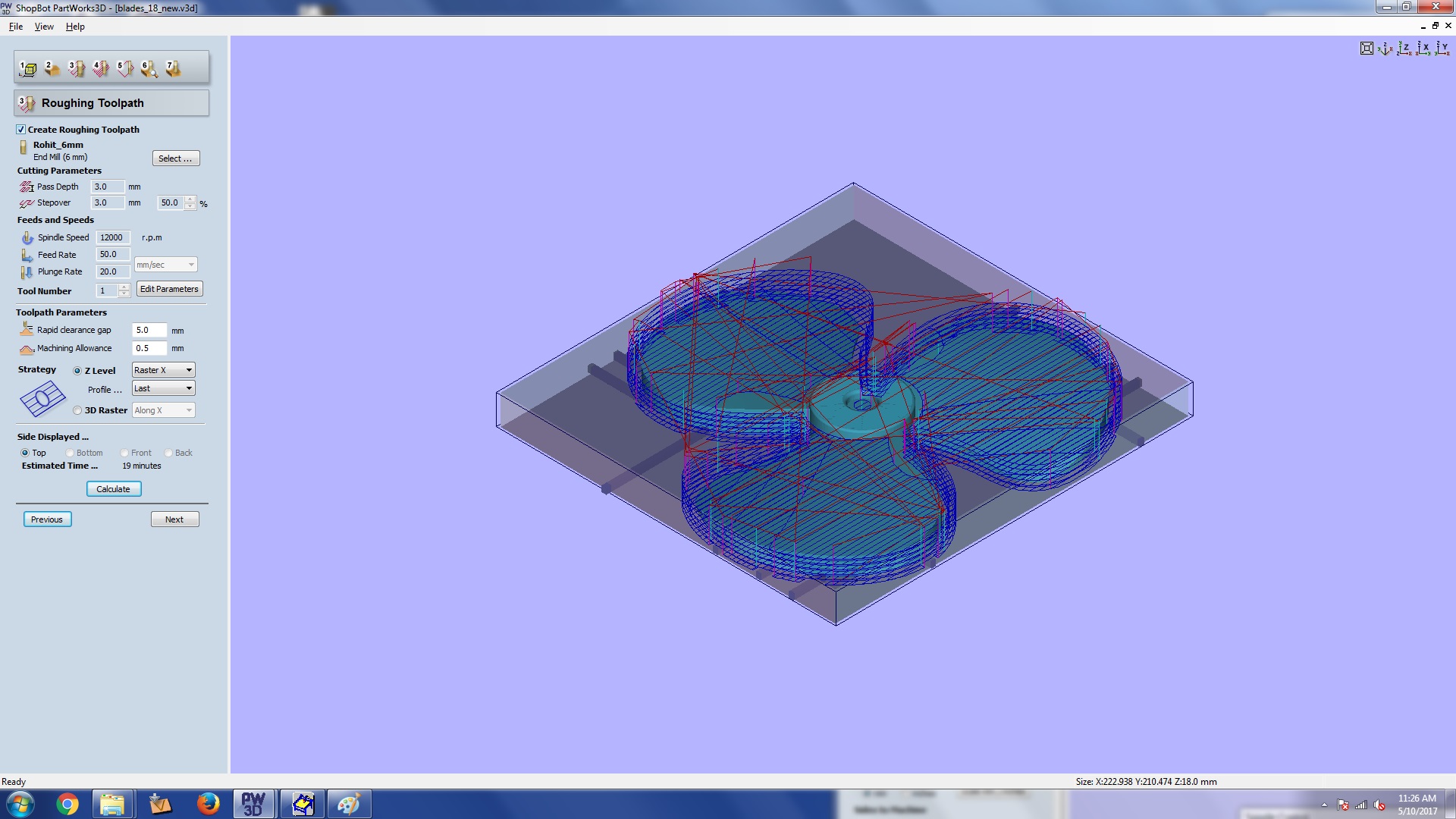
Step 3: roughing section
-
This is finishing tool path section. Here also we can put settings as we did in last section.
For finishing we use a ball nose end mill and for roughing a flat nose one. Once you are done click
calculate
before moving on to the next section. Do clink calculate agian everything you make changes.
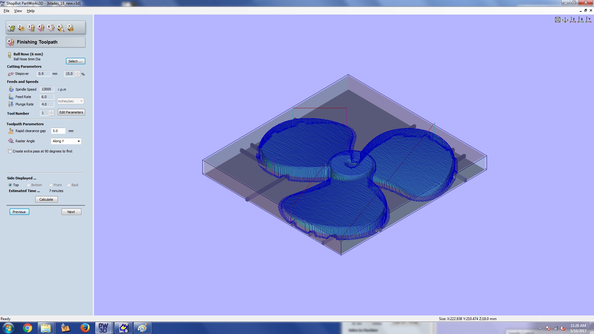
Step 4: finishing section
-
This is cut out section. Here we can provide settings for cuting out. Once you are done click
calculate
before moving on to the next section.
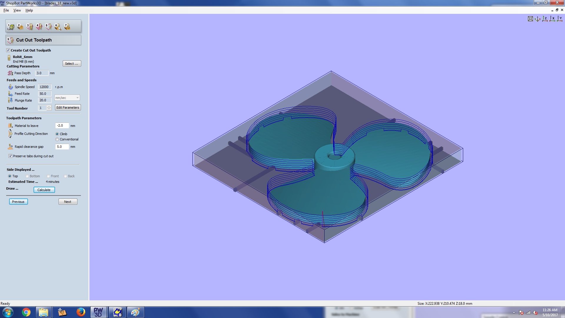
Step 5: cut out section
-
Once we are done with all the settings we are taken to the preview area, where we can review how the
roughing and finishing is going to happen. If you find some issue. Do go back and make changes.
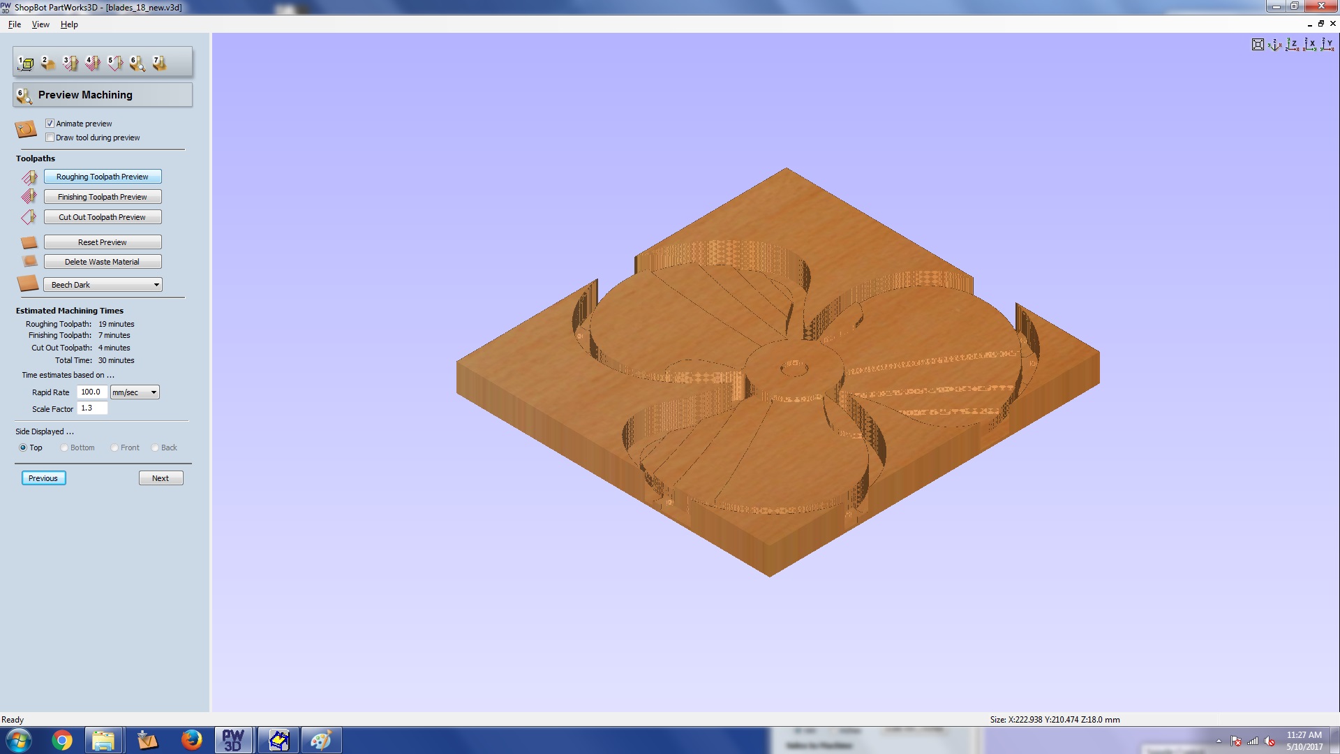
Step 6: Preview
-
Finally you can save the tool pathes as stp files for your shopbot. There are other file options also
in the dropdown. Save the roughing, finishing and cutting toolpaths.
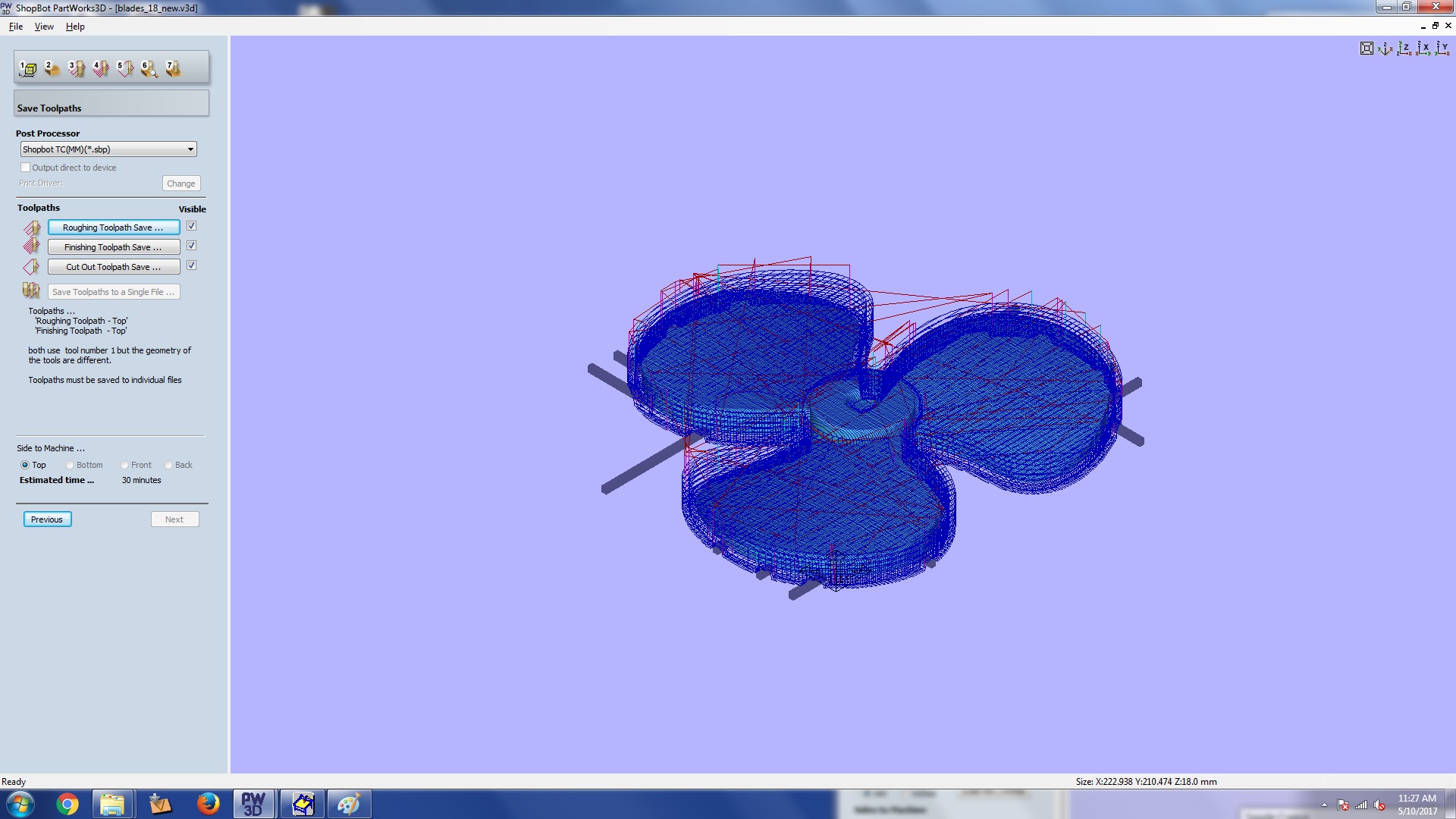
Step 7: saving toolpaths
e. Making the model in shopbot
-
First load the material and set zero in the machine. Load the roughing stp file and start cutting.
After rouging passes
-
After the roughing passes you can bring back the machine to the initial zero location already set
and then load the stp file for finishing
operation.
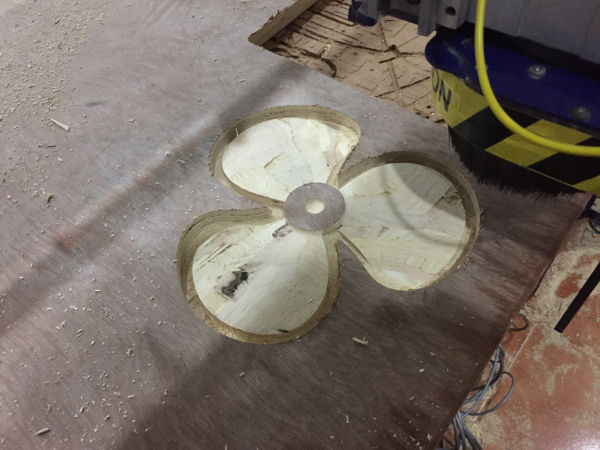
After finishing passes
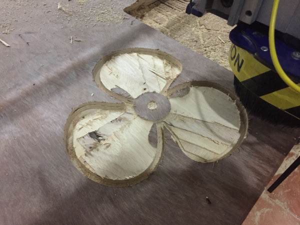
- After finishing you can do the cutting operation.
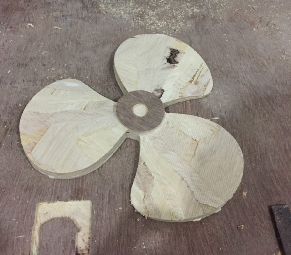
After cutting
f. Cutting the fabric
I wanted to cut the lint cotton cloth in the shape of the blade so that i dont have to trim away the material after apply the matrix.
I use the laser cutter to cut the shape in the fabric for me. I am using one more material made of jute, which i cut manually to the
required shape.
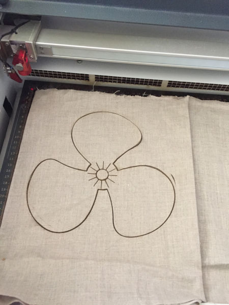
Laser cutting the fabric
g. Making the composite
- First i used to cellotape to create a coating on the top on the wooden part.
- I placed the fabric on the wooden part and tied them with jute. I also have a layer of jute in between
the cloth layers
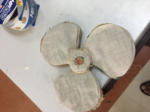
Fabric arranged and tied on the wooden model
-
As mentioned we are having Adthya epoxy
resin in our lab. This is what i am using for the work. Sone of the properties are listed below.
- Mixing ration 100:50(A:B)
- Curing time 4 hours
- Mild heating enhances curing
Now i mixed Adithya epoxy A and B in ratio 2:1 (100g, 50g) and wetted the fabrics in it. You can see that i have already cut the cloth in laser with necessary shape and size. I have also tied the cloth to the mould so that the region where the blades join the ring forms properly. As i have everything tied up i had to take the mixture and wet each cloth layer by layer. This is the picture of me wetting it layer by layer. The material used as thread for tieing is jute, so with will form a rigid structure with the other parts enhancing shape and strength. I am using 6 layes of cotton cloth and 1 layer of jute as my fiber material.
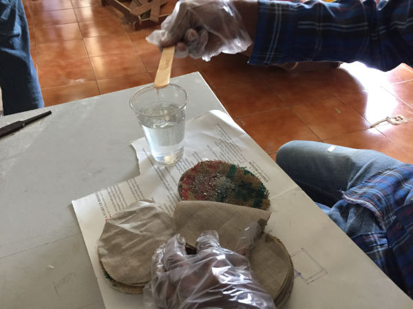
Adding the resin on the fabric
-
Finally i covered the whole thing with polythene sheet tightly and kept it for setting.
Covering the model
-
To get a perfect shape i placed the above setting sandwiched on a jute sac and a bag of saw dust on
top of it and over which i kept a weight.
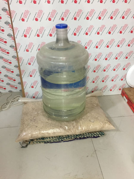
Keeping the model for setting
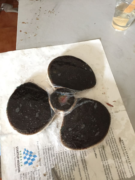
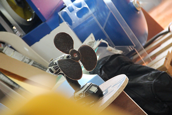
h. Results
After 24 hours i too the setup out and removed the polythene cover on the top and then removed the model out of the mould. The following are the results.


i. Problems and solutions
- The part where the blade joins the ring has two 90degree bends. I could not by ay means make the composite sit like that. Finally i used jute threads to tie the composite to the plywood mould. This solved the issue.
- Our vaccum pump was not creating enoug vaccum to pull the composite strongly to the mould. Finally i decided and put the mould- composite pair sandwiched in jute sack and a weight was kept on top of it. This in-fact gave enough pressure for proper setting and good finish in the composite.te
i. Summary
- Learned to use composites.

This work is licensed under a Creative Commons Attribution-NonCommercial-ShareAlike 4.0 International License.