Project Development
Goals
- Complete your final project. Track and document your progress.
GUI
At the time of writing the GUI is still in its embryonic stage: it only converts normal text to 6 cell Braille. The biggest issue I had while writing these few lines of code was the character encoding: python3 defaults to unicode but it took me a while to understand that, by default, the QT5 installed in my laptop used Latin1 as defaul encoding in their text widgets.
The next step will involve the creation of a dictionary that would map each Braille character to a byte (64 bytes for 6 cell braille, 255 for the extended 8 cell variant) and will facilitate the sending of the data array via serial port.
Last, but not least, the GUI will offer the possibility to translate into different language specific Braille (English grade1 and 2, Italian, French, Spanish, German are just some of the options available in Liblouis).
The GUI, even if still far from being aesthetically pleasing, is totally operational: it lets the user insert the text, it previews the braille translation and sends it to the machine via a serial port that can be defined by the user; for the time being the only language available is English Grade 2 braille, other languages will follow.
Here is the code in its current form (for the latest version and its evolution check the fabacademy git repo); the italian docstrings were originally intended for internal use only, they will get translated in english in order to automate the creation of documentation using Sphinx (truth to be told, this task has a really low urgency rigth now).
#!/usr/bin/env python3

import sys
import binarybraille
import subprocess
import time
import serial
from PyQt5 import uic
#from PyQt5.QtCore import QDateTime
from PyQt5.QtWidgets import QApplication, QWidget, QDialog, QMessageBox, QMainWindow


def empty_text():
    warning = QMessageBox()
    warning.setWindowTitle('Warning')
    warning.setText('No Braille text to print!')
    warning.setStandardButtons(QMessageBox.Ok)
    warning.exec_()

##############
## MAIN WIN ##
##############

class main_win(QMainWindow):
    braille_text = ''
    braille_text_byteobject = ''
    paragraphs_list = []
    binary_paragraphs_list = []
    integers_list = []


    def __init__(self, parent=None):
        super(main_win, self).__init__(parent)
        self.initUI()

    def initUI(self):
        uic.loadUi('ui.ui', self)
        self.setWindowTitle('LCD input application')
        self.translate_button.clicked.connect(self.show_braille_text)
        self.print_button.clicked.connect(self.print_braille_text)
        self.show()

    def show_braille_text(self):
        """Prende il testo dato in input dall'utente
        e lo trasla in Braille, secondo la lingua scelta
        dall'utente (questa seconda fase è ancora da implementare)
        """
        self.input_text = self.input_field.toPlainText()

        shout = subprocess.Popen(["echo", self.input_text], stdout=subprocess.PIPE)
        self.braille_text_byteobject = subprocess.check_output(["lou_translate", "unicode.dis,en-ueb-g2.ctb"], stdin=shout.stdout)
        self.braille_text = self.braille_text_byteobject.decode('utf-8')
        return self.braille_field.setPlainText(self.braille_text)

    def print_braille_text(self):
        """Prende il testo Braille, lo divide in paragrafi,
        prende ciascun paragrafo, accoppia carattere braille a
        relativa rappresentazione binaria, trasformando ciascun elemento
        della lista dei paragrafi in una lista di stringhe, trasforma
        ciascuna stringa nell'int corrispondente, invia la lista di int
        tramite seriale
        """
        self.binary_paragraphs_list = []
        self.integers_list = []
        if self.braille_text == '':
            return empty_text()
        self.ser = serial.Serial(self.lineEdit.text(), int(self.lineEdit_2.text()), timeout=2)
        self.get_paragraphs_list(self.braille_text)
        self.paragraphs_to_binary(self.paragraphs_list)
        self.binary_to_integer_list(self.binary_paragraphs_list)
        self.send_to_board(self.integers_list)

    def get_paragraphs_list(self, text):
        """Divido il testo in paragrafi.
        Trimma i paragrafi vuoti che le qt si lasciano dietro.
        """
        self.paragraphs_list = text.split('\n')
        if self.paragraphs_list[-2] == '':
            self.paragraphs_list = self.paragraphs_list[:-2]
        else:
            self.paragraphs_list = self.paragraphs_list[:-1]
        print('Braille text:')
        print(self.paragraphs_list)
        print('\n\n')

    def paragraphs_to_binary(self, par_list):
        """Trasforma ciascun elemento di self.paragraphs_list e lo trasforma
        in una lista di stringhe, rappresentazione binaria di ciascun carattere braille.
        Nota per me: potrei usare una list comprehension qui, per rendere il tutto più agevole
        """
        for par in par_list:
            binary_string = []
            for character in par:
                binary_string.append(binarybraille.binary_braille.get(character, '00000000'))
            self.binary_paragraphs_list.append(binary_string)
        print('Binary rapprentation of the text:')
        print(self.binary_paragraphs_list)
        print('\n\n')

    def binary_to_integer_list(self, binary_lists):
        """Trasforma binary_lists in array di liste di interi, che
        mi serviranno per essere spediti via seriale alla board.
        Ritorna lista di liste di interi. Anche qui, forse list comprehension
        """
        for element in binary_lists:
            temp_integer_list = []
            for b in element:
                temp_integer_list.append(int(b, 2))
            self.integers_list.append(temp_integer_list)
        print('Corresponding integers to send:')
        print(self.integers_list)

    def send_to_board(self, ints_list):
        """Invia gli int alla board
        """
        for element in ints_list:
            for num in element:
                self.ser.write(num)
                #print(num)


################
##  Start it  ##
################
if __name__ == '__main__':
    app = QApplication(sys.argv)
    ex = main_win()
    sys.exit(app.exec_())
Here is a quick video showing the translation process, with added a shell output that should illustrate the GUI inner workings (in the final product the GUI won't print anything to the shell):
PCB design
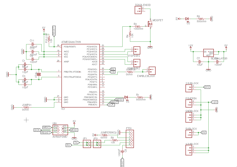
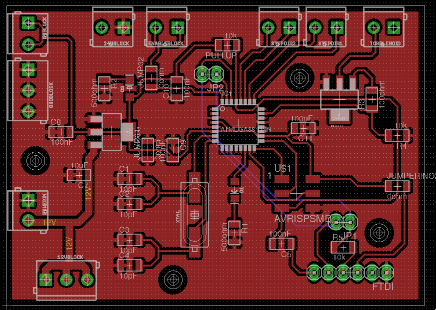
The board for my final project is, without a doubt, the most complex board I designed during these last 6 months. It's based on the ATMega328p microcontroller, in order to guarantee a full compatibility with arduino libraries, and it houses 2 alegro stepper driver carriers, a mosfet (used as a switch to operate the solenoid), the solenoid itself with its flyback diode, a linear voltage regulator (from 12V to 5V).
The pcb routing itself is pretty self-explanatory, so I'll briefly analyze its main points:
- 3 0.1uF decoupling capacitors, one for each vcc/gnd couple of pins
- a 16 MHz crystal with its capacitors (I needed 2 couple of 10pF caps in parralel, for in our lab we don't have any 20ish pF cap, as required by the ATmega328p datasheet)
- a linear voltage regulator to drop the voltage from 12V (used by the motors) to 5V (for the rest of the board), and its input/output capacitors
- a MOSFET to operate the solenoid, which is independently powered by a 24V bench power supply; I had to make the footprint for this component by myself, taking the LM1117 as a starting point (my ad hoc library is available here)
- 2 leds (and corresponding resistors) for debugging purpose: one connected to vcc and gnd (to know it the board is powered at a glance) and one connected to the microcontroller
- a 10k pullup resistor between rst and vcc
- isp connector
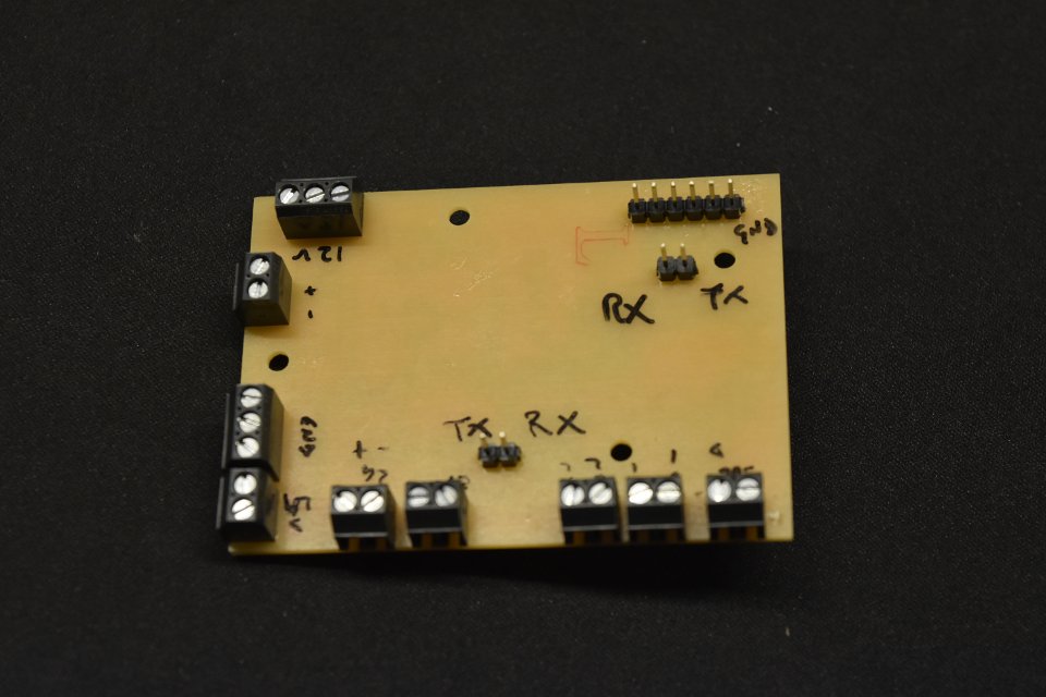
- FTDI connector (the resistor on the TX line and cap on RST are not longer present in my second iteration of the board. For their rationale check this link and this link)
- All the lock connectors needed to route the wires to the 2 pololu suppor boards (more on this later)
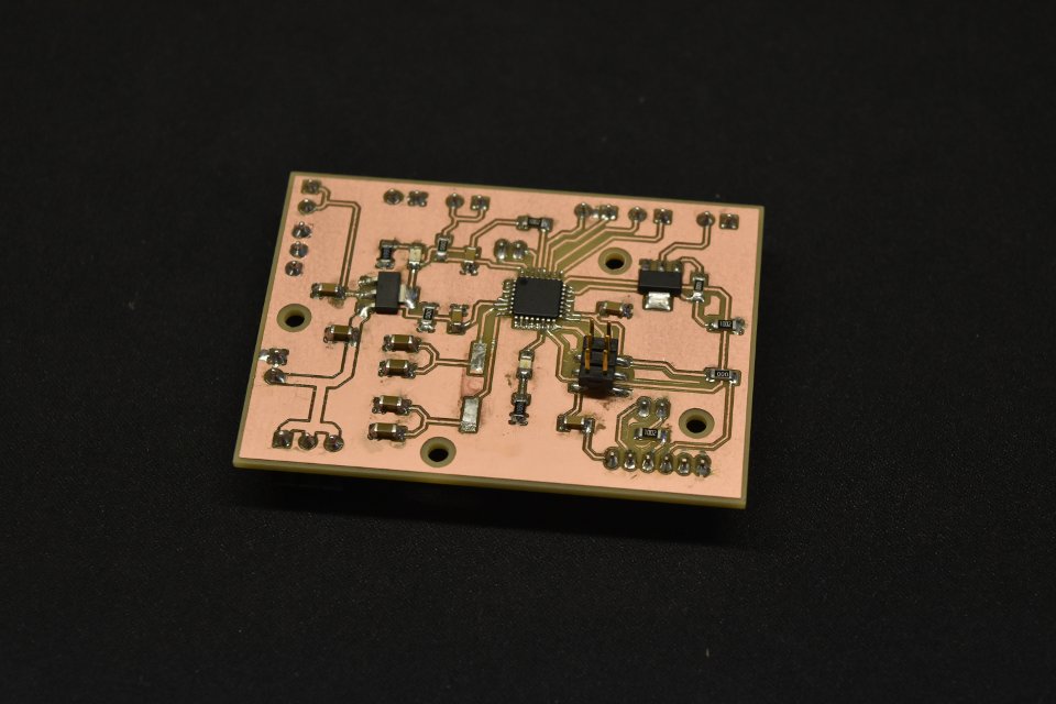
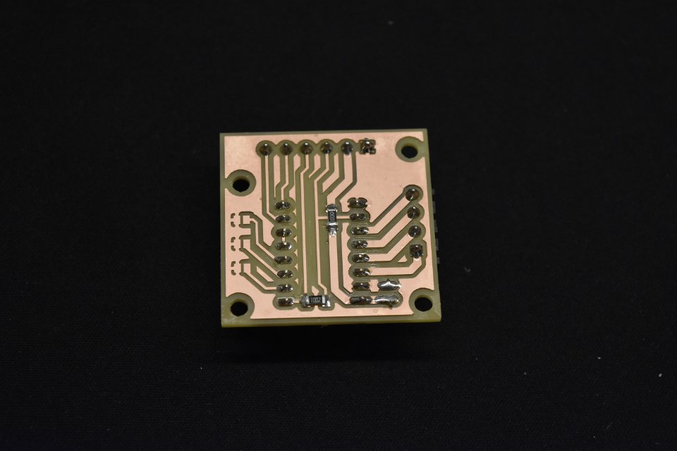
Alas the first version of the board didnt'd work at all at first, because of a couple of cold solder joints. As you can see from the following image the debuggin process took quite a toll on the integrity of the board (in this particular shot I had removed the crystal, under the delusion that it was a faulty one - turns out my mind slipped while harvesting the components for the stuffing and I picked 10uF instead of 10pF caps for my crystal)
In order to drive the stepper motors I decided to use a Pololu A4988 stepper driver. I designed a stand alone board for it because I wanted the ability to move them close to the motors. In order to make it right I followed the datasheet and the suggestions found on the manufacturer official site
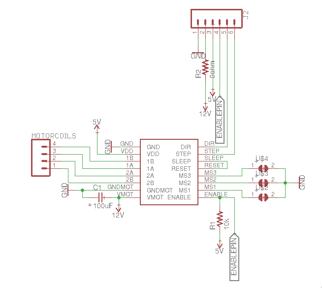
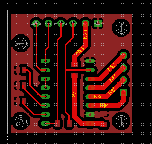
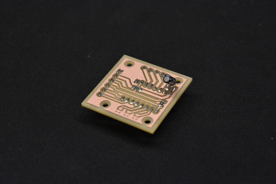
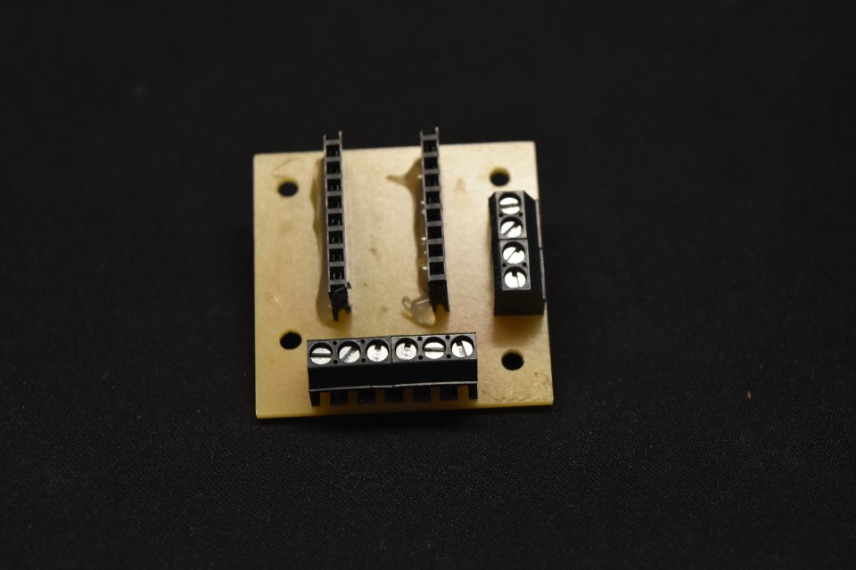
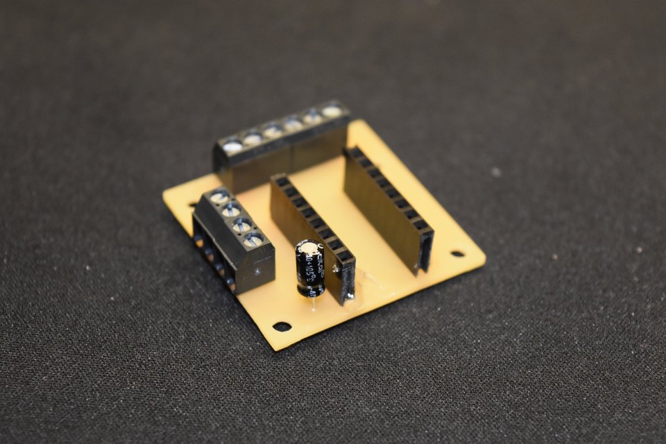
After finishing the first board I realized I made a bad design call: not knowing that we had no 47uF cap in a SMD form factor I placed it on top of the board, using the footprint found in the fablab library. The board would work nonetheless, but the soldering was a little too unpractical. Thus I fired up Eagle again and ditched the cap footprint, going instead for a 2pin connector which would allow me to place the electrolytic capacitor on the back of the board:
I then wired them to an Arduino and adapted a quick script (original took from here) to check if everything was right. The motor reacts as expected.
#define enablePin 13
#define stepPin 12
#define dirPin 11

void setup() {
  pinMode(stepPin,OUTPUT);
  pinMode(dirPin,OUTPUT);
  pinMode(enablePin,OUTPUT);
}
void loop() {
  digitalWrite(dirPin,HIGH);
  for(int x = 0; x < 200; x++) {
    digitalWrite(stepPin,HIGH);
    delay(1);
    digitalWrite(stepPin,LOW);
    delay(1);
  }
  delay(3000);

  digitalWrite(dirPin,LOW);
  for(int x = 0; x < 200; x++) {
    digitalWrite(stepPin,HIGH);
    delay(1);
    digitalWrite(stepPin,LOW);
    delay(1);
  }
  delay(3000);
}
Board code
After designing the board I got down writing the code for the board. The code would take a fixed set of integers from the serial port, write them in an array and then traverse that array 3 times, each time checking the relevant couple of digits in the binary rappresentation of the integers (via the bitRead function) and firing the solenoid when a 1 is found; at the end of each row the second stepper motor is fired, the paper gets pulled a little and the code starts over again.
Here you can find the code repository.
#define stepA 16
#define dirA 17
#define stepB 18
#define dirB 19
#define enablePin 15

#define fireSolenoid 14

#define interCellStep 20
#define changeCellStep 27
#define fullCellStep 67

#define changeLineStep 25

int myData[25];
int cellsWritten = 0;

void setup() {
  Serial.begin(9600);
  delay(100);
  pinMode(fireSolenoid, OUTPUT);
  pinMode(enablePin, OUTPUT);
  pinMode(stepA, OUTPUT);
  pinMode(dirA, OUTPUT);
  pinMode(stepB, OUTPUT);
  pinMode(dirB, OUTPUT);
  digitalWrite(fireSolenoid, LOW);
  delay(100);
}

void loop() {
  if (Serial.available() > 0) {
    for (int i = 0; i < 25; i++) {
      myData[i] = Serial.parseInt();
      //Serial.println(incoming[i], BIN);
    }
    for (int i = 0; i < 25; i++) {
      checkFirstRow(myData[i]);
      cellMove();
    }
    newLine();
    for (int i = 0; i < 25; i++) {
      checkSecondRow(myData[i]);
      cellMove();
    }
    newLine();
    for (int i = 0; i < 25; i++) {
      checkThirdRow(myData[i]);
      cellMove();
    }
    newLine();
  }
  delay(1000);
}

void checkFirstRow(int x) {
  if (bitRead(x, 1) == 1) {
    digitalWrite(fireSolenoid, HIGH);
    delay(5);
    digitalWrite(fireSolenoid, LOW);
  }
  interCellMove();
  if (bitRead(x, 4) == 1) {
    digitalWrite(fireSolenoid, HIGH);
    delay(5);
    digitalWrite(fireSolenoid, LOW);
  }
  delay(10);
}

void checkSecondRow(int x) {
  if (bitRead(x, 2) == 1) {
    digitalWrite(fireSolenoid, HIGH);
    delay(5);
    digitalWrite(fireSolenoid, LOW);
  }
  interCellMove();
  if (bitRead(x, 5) == 1) {
    digitalWrite(fireSolenoid, HIGH);
    delay(5);
    digitalWrite(fireSolenoid, LOW);
  }
  delay(10);
}

void checkThirdRow(int x) {
  if (bitRead(x, 3) == 1) {
    digitalWrite(fireSolenoid, HIGH);
    delay(5);
    digitalWrite(fireSolenoid, LOW);
  }
  interCellMove();
  if (bitRead(x, 6) == 1) {
    digitalWrite(fireSolenoid, HIGH);
    delay(5);
    digitalWrite(fireSolenoid, LOW);
  }
  delay(10);
}

void interCellMove() {
  digitalWrite(dirA, HIGH);
  for (int x = 0; x < interCellStep; x++) {
    digitalWrite(stepA, HIGH);
    delay(1);
    digitalWrite(stepA, LOW);
    delay(1);
  }
}

void cellMove() {
  digitalWrite(dirA, HIGH);
  for (int x = 0; x < changeCellStep; x++) {
    digitalWrite(stepA, HIGH);
    delay(1);
    digitalWrite(stepA, LOW);
    delay(1);
  }
  cellsWritten++;
}

void newLine() {
  digitalWrite(dirA, LOW);
  for (int x = 0; x < (cellsWritten*fullCellStep); x++) {
    digitalWrite(stepA, HIGH);
    delay(1);
    digitalWrite(stepA, LOW);
    delay(1);
  }
  cellsWritten = 0;
  digitalWrite(dirB, HIGH);
  for (int x = 0; x < changeLineStep; x++) {
    digitalWrite(stepB, HIGH);
    delay(1);
    digitalWrite(stepB, LOW);
    delay(1);
  }
}
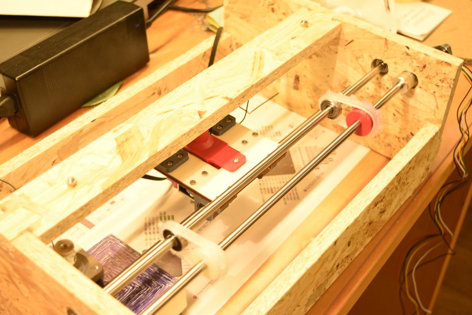
Design
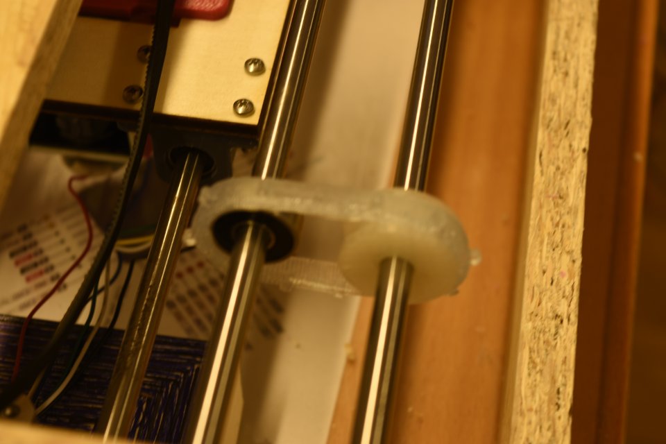
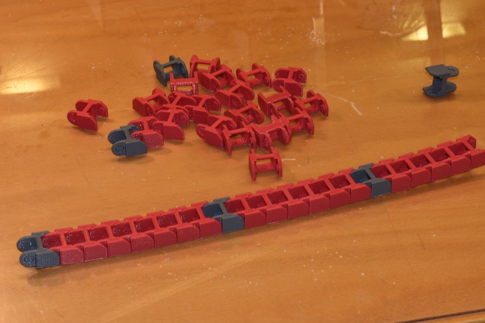
But for the linear and ball bearings, the solenoid, the tempered steel rods and the chain cable holder (taken from Thingieverse) I drew all the parts with Onshape, the links to the working files can be found in the links section below.
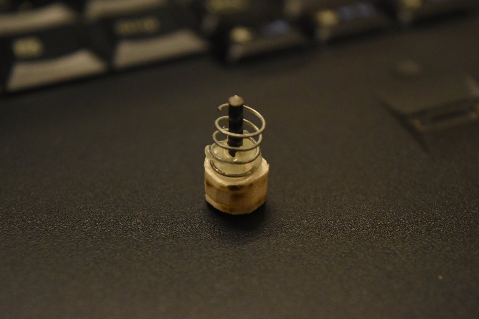
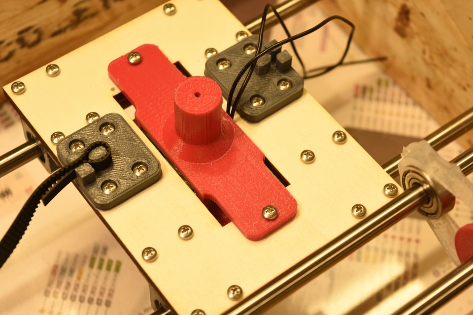
The actual embossing is done by a nail I hammered in the middle of a plywood disc and then blunted with a grinding gear; I then glued a spring on it, in order to help it return to its original position after the solenoid activation.
This end effector is then housed in a shell that will be fastened to the central sliding platform.
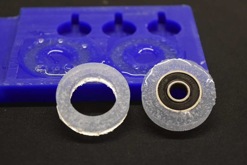
Concerning the paper feeding mechanism I made a couple of silicone tracks in order to take advantage of the holes on the feeding rails on each side of the paper. Alas they don't work quite as expected: the little bumps on the tracks fit in the holes too tightly and they refuse to let go of the paper once the bar start moving, therefore the paper becomes all mangled after a few cm of advancements. For the next iteration I plan to squeeze the paper between two couples of ball bearing covered in silicon.
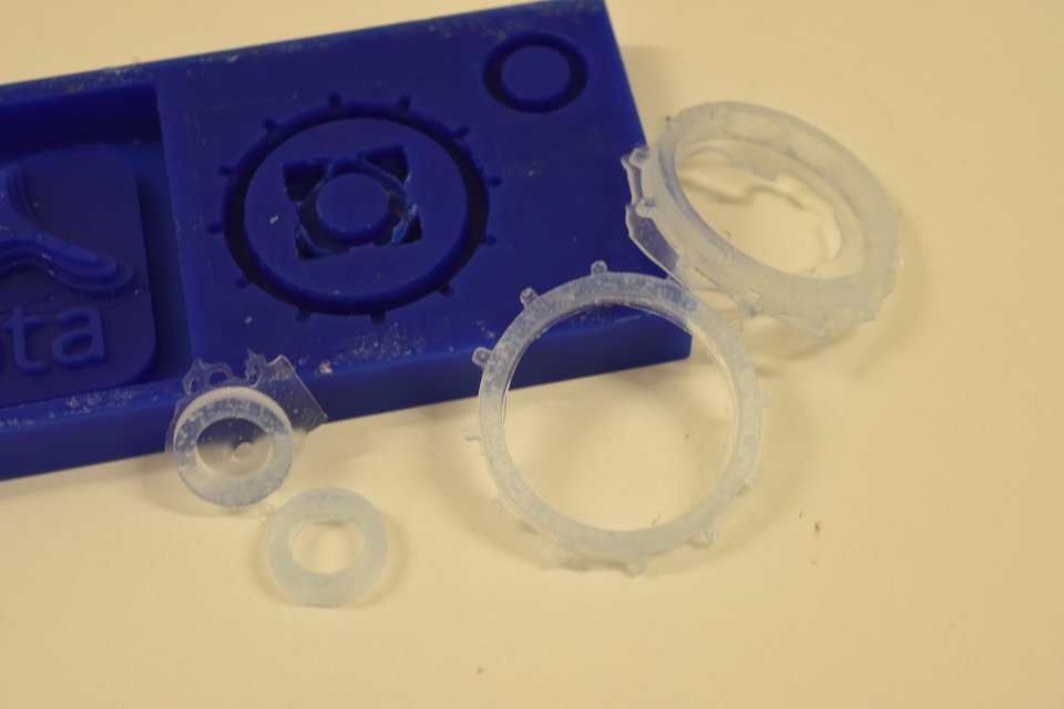
I modified the design in order to feed the paper through 2 vertical couples of silicone rolls, therefore I had to remake the mold from scratch.
Schedule, final thougths and considerations
The schedule for the future plans outlined during week 17 is still valid, and it seems to me that the deadlines scheduled to implement the upgrades (in a spiral fashion) are quite realistic.
What has worked? What hasn't?
To my great pleasure the rationale behind the main components proved to be right: the embossing system leaves good, defined traces on the paper, the new feeding system grips the paper sheet firmly and the logic behind my board proved to be right (up to a point, more on this later).
On the other hand, the motor system is still messy, with the timing belt enveloping the embosser head (the friction will tear it up pretty quickly, I'm afraid), the motor holder way to close to the rod bars (it makes for an unpleasant experiece while fastening it) and still the lack of a system to manually adjust the pression of the embosseing head on the paper. As I said, the board proved to be right up to a point, because I used a flyback diode with the wrong specifications (when turned off the solenoid is switched off the current attemps to keep flowing, possibly harming the microcontroller), and my MOSFET fried as a result. For further testing I had to connect my motor drivers board to an arduino and completely forgo the solenoid activation.
What tasks remain? How will I complete them in time?
It's clear that I'll need to solder another master board from scratch before the final deadline. This may be difficult because if the other diodes we have in the lab won't meet the right specification I may need to order something ad hoc from digikey or any other reseller.
What questions still need to be resolved?
The other questions still without answers concern future improvements: how can I change my GUI in order to handle longer texts? If I want to speed up the embossing using 6 solenoids (thus writing one cell in a single passing) how can I arrange them in order to keep the right dimensions of the cell itself (solenoids powerful enough to leave a trace on paper are quite big)? For now I used normal paper, whereas specific braille paper is way more heavy: will my 32V solenoid be able to dent it in a satisfactory fashion? And if it will fail to do so, what alternative methods are left to me? There are only the first questions that I need to give an answer to if I want to take my project a step further.
what have I learned?
In no particular order:
- Bugs and behaviours not accounted for hide in any line of code I write; any time estimate should be at least doubled
- After all this time I still am unable to guess how much time a print will take, and this "time deficiency" stacks up really fast
- When you'll thing you have your design sorted out, that's when you discover that you forgot about something vital
- Endless screws may be a better system for linear motion than timing belts and pulleys; maybe more expensive, but simpler
- Being a little more confortable with pure C and ditching the Arduino environment altogether would be a smart move, in terms of freedom and power of choice
- Having a ground plane on big pcbs is handy, but the soldering can sometimes become problematic on bigger ground pads, because the heat tends to dissipate quickly
Links
- tar.gz - archive containing all the files needed to reproduce my project (3d models, code, eagle working files, drawings for the parts to be cut) - check the complete contents of the archive at the bottom of the project page
- Onshape working files
- Eagle library file - custom library for the MOSFET