Networking and Communications
Goals
- Design and build a wired &/or wireless network connecting at least two processors
Wired network
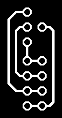
First of all I tried to connect my previous board (made during week 8 and 11) using the I2C bus and an Arduino board as a master. Since I lacked ribbon cable connectors or enough exposed pins on my slave boards to use jumpers I had to fire up eagle and design a little support board to douple the SDA, SCL, VCC and GND headers on my middle slave
I then confronted the Attiny44 pinout with an arduino uno pinout and connected my boards.
On a software level I noticed that the attiny44 has no TWI support, using the standard Wire library was, consequently, a no go.
I used TinyWireS as a drop-in replacement, manually installing it in my arduino library folder (under GNU/Linux it defaults to /home/youruser/Arduino/libraries, anyway you can check the right path from inside the IDE, under preferences.
I then configured my arduino IDE to support my attiny board, following the instructions found here: long story short you have to point the board manager to an external repository and then install the board definitions from there
With my IDE finally configured I wrote 2 simple sketches for my arduino and my boards; in order to test the basic connection I kept the code to the bare minimum, with my arduino trying to retrieve 2 different numbers from my slave boards
//Master node code
#include < Wire.h >

#define slave1 8
#define slave2 12


void setup() {
  Wire.begin();
  Serial.begin(9600);
}

void loop() {
  Wire.requestFrom(12, 1);
  while (Wire.available()) {
    int n = Wire.read();
    Serial.print("Node1: ");
    Serial.print(n);
    Serial.print('\n');
  }
  delay(1000);
  Wire.requestFrom(8, 1);
  while (Wire.available()) {
    int n = Wire.read();
    Serial.print("Node2: ");
    Serial.print(n);
    Serial.print('\n');
  }
  Serial.print("done\n");
  delay(4000);
}
//Slave1 code
#include

void setup() {
  TinyWireS.begin(12);
  TinyWireS.onRequest(send);
}

void loop() {
   TinyWireS_stop_check();
}

void send() {
  TinyWireS.send(1);
}
As you can see TinyWireS is a total drop-in replacement for the standard Wire library, except for send in place of write and for that "TinyWireS_stop_check();". To my undertanding tha function is needed since the attiny44 lacks a hardware interrupt for “end-of-transmission” events, so we got to keep checking for them via software.
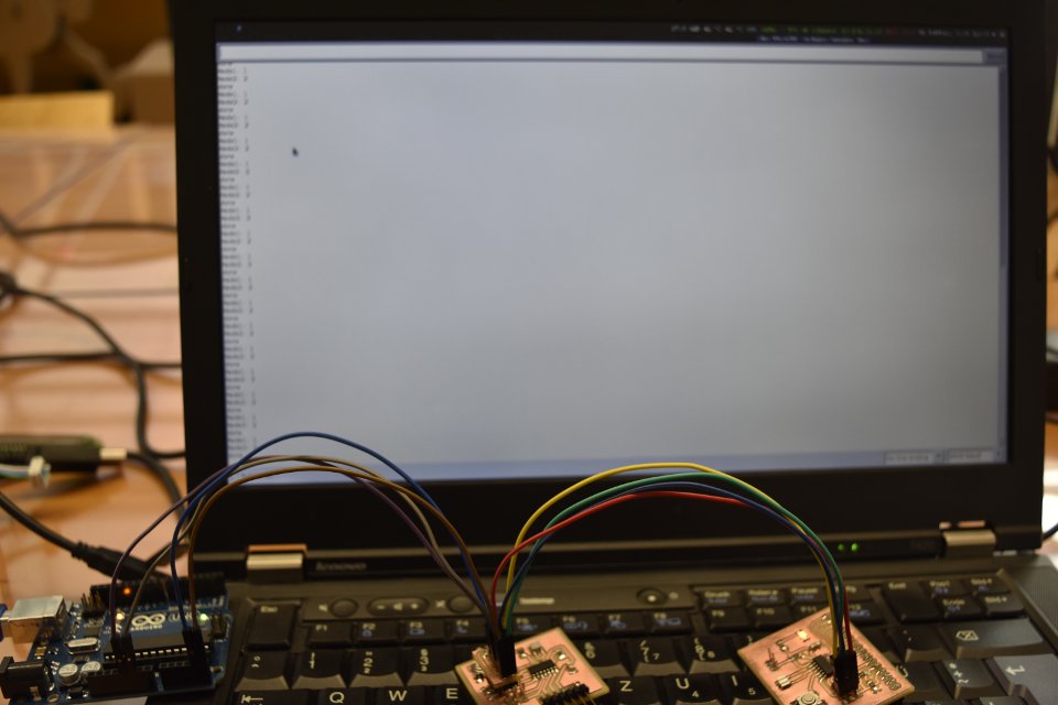
My basic code worked as intended, so I moved on (the serial terminal shows a endless list of "node 1: 1, node2: 2, done").
Wifi
I then tried to use an ESP8266-01module we had lying around in the lab. This little board is somewhat limited (it has only 2 I/O pins exsposed) but suited me fine for a didactic purpose.
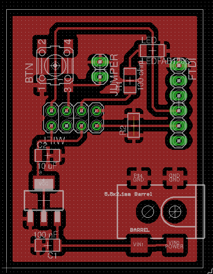
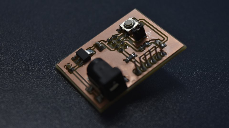
First of all I designed a dev board to supply power to the module from an external source (a 9V - 1A Arduino power supply) with a linear voltage regulator, a button and a led (in order to make some basic interactions between 2 modules) and jumper (in order to program the board you have to connect GPIO0 to ground).
After completing the first board I realized that we had only one wifi module in the lab, so I forwent the initial idea of having 2 boards interacting and simply tried to connect the board to my lab network:
#include < ESP8266WiFi.h >

const char* ssid = "schiara";
const char* password = "*******";
void setup(void) {
Serial.begin(115200);
WiFi.begin(ssid, password);
  while (WiFi.status() != WL_CONNECTED) {
  delay(500);
  Serial.print(".");
  }
Serial.println("");
Serial.println("WiFi connected");
Serial.println(WiFi.localIP());
}

void loop() {
}
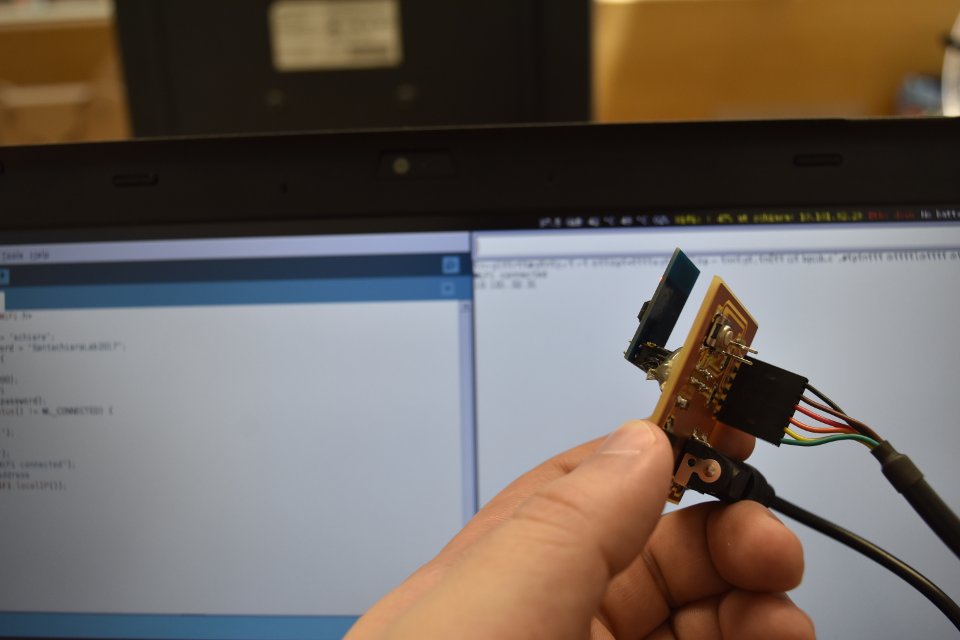
(Ok, this picture should show a serial monitor stating "Wifi connected" and my ip address, you have to trust my word on this)
Conclusions
All things considered I'm disappointed in myself, for I did very little compared to my initial plans. I'll keep exploring this topic in the next weeks.
Links
- Week 15 - eagle files (tar.gz)
- Internet of Things with ESP8266 - nice introductory book
- Esp8266 basic tutorial