Introduction
The assignments of this week was:- Make something big on a (CNC machine)
DESIGN
For this week assignment I decided to build a table. I know that it isn't the most original things to do, but as final project I want to build a tea table 2.0 (see final project page) so I thought this week was perfect to understand how can do it and what errors to avoid.
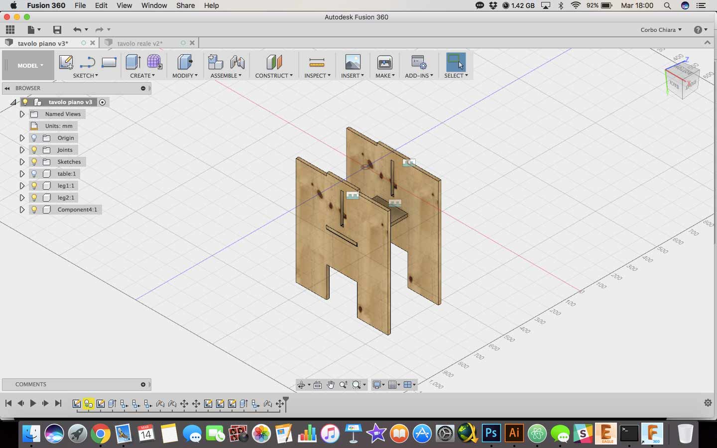
I have draw a sketch of it on Fusion 360. Why a 3D software? Because whit it I can create a preview of my works by assembling all pieces with join tools. Then I have decide to use the Laser Cutter for build a scale model of it and this is the results.
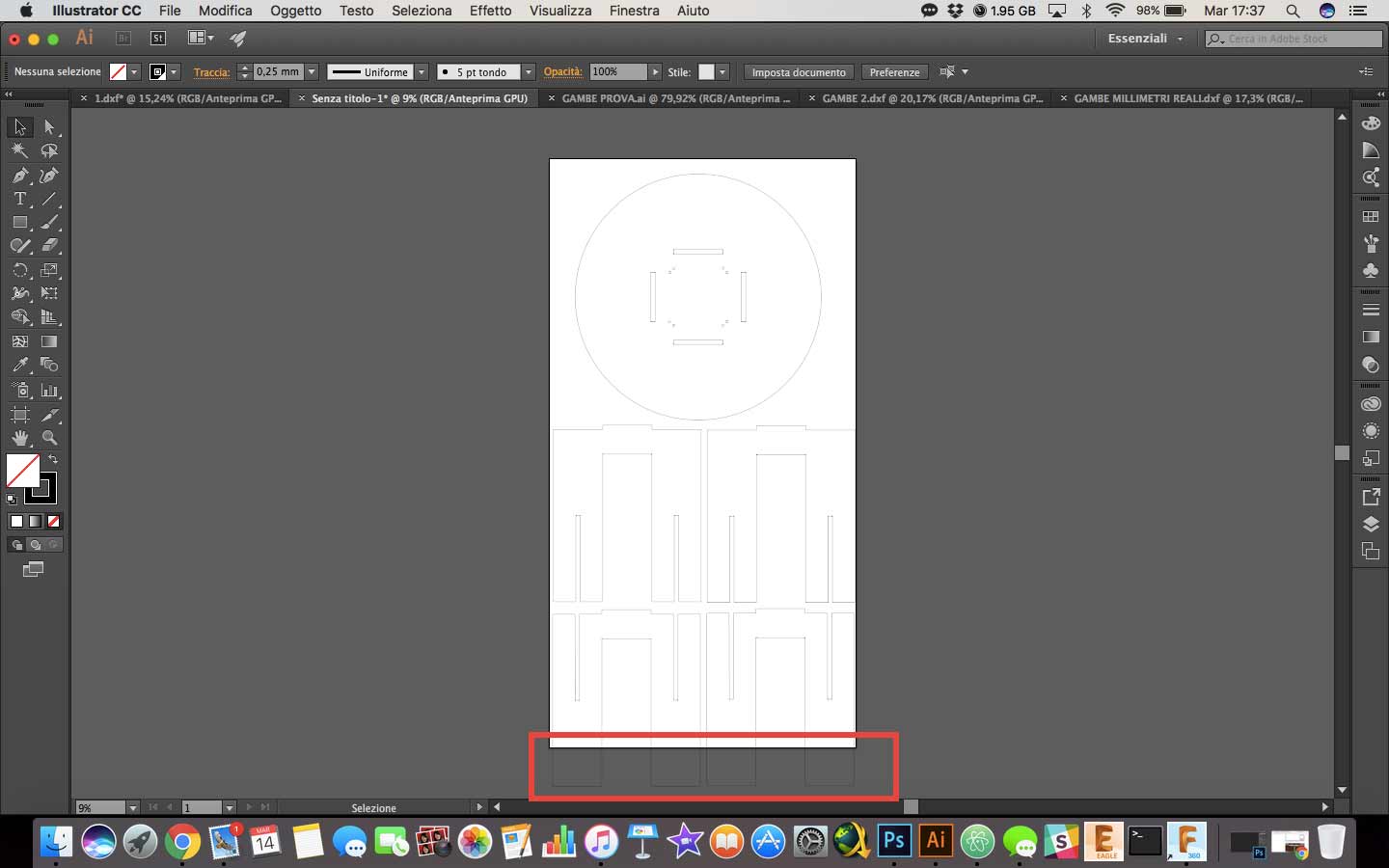
At this point I have created a new Illustrator's document with the real OSB board dimension, where I have imported all my pieces for check if I have enough space for cut it all. I sunrealize the space was not enough, so I had to change my model.
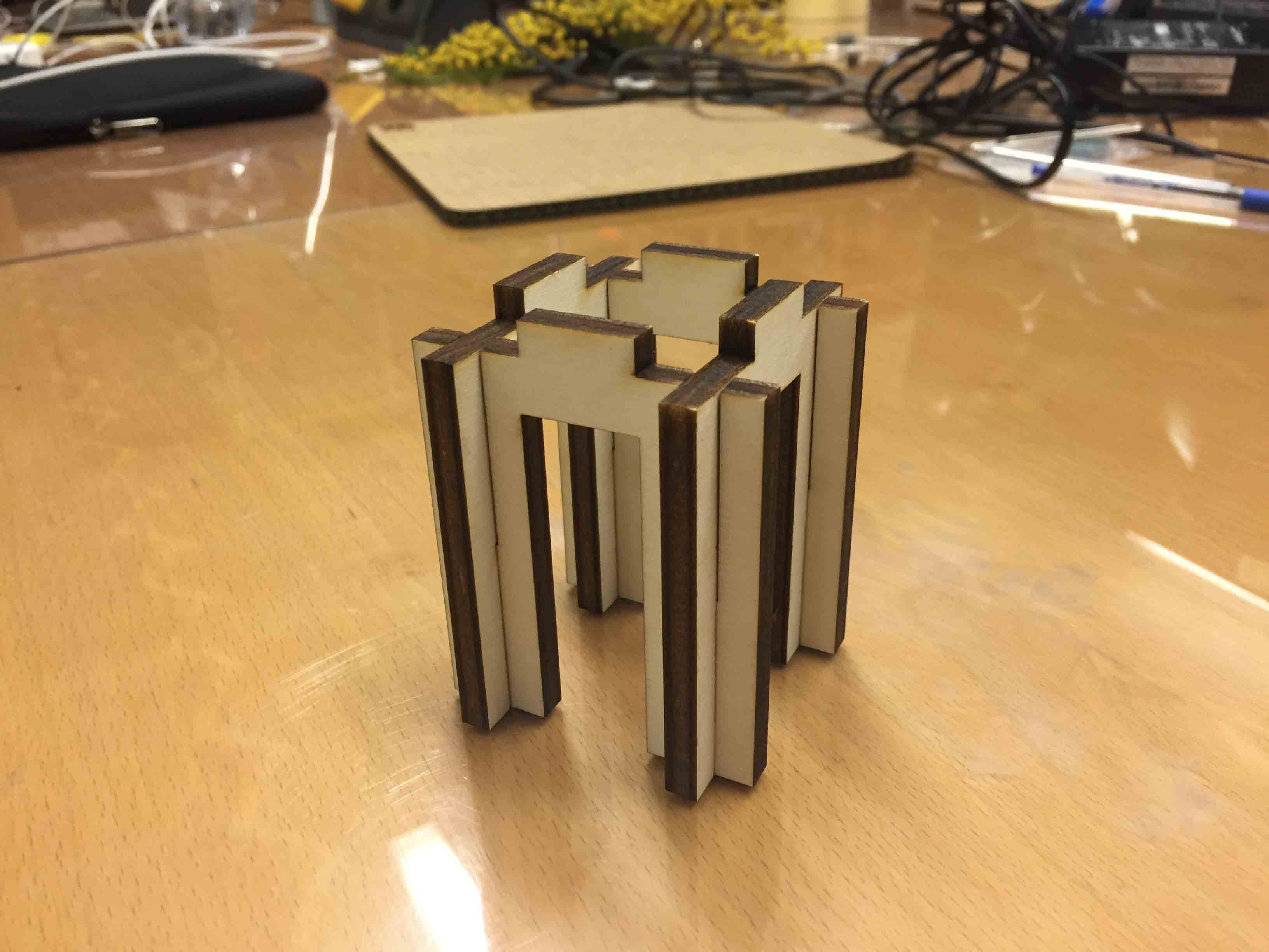
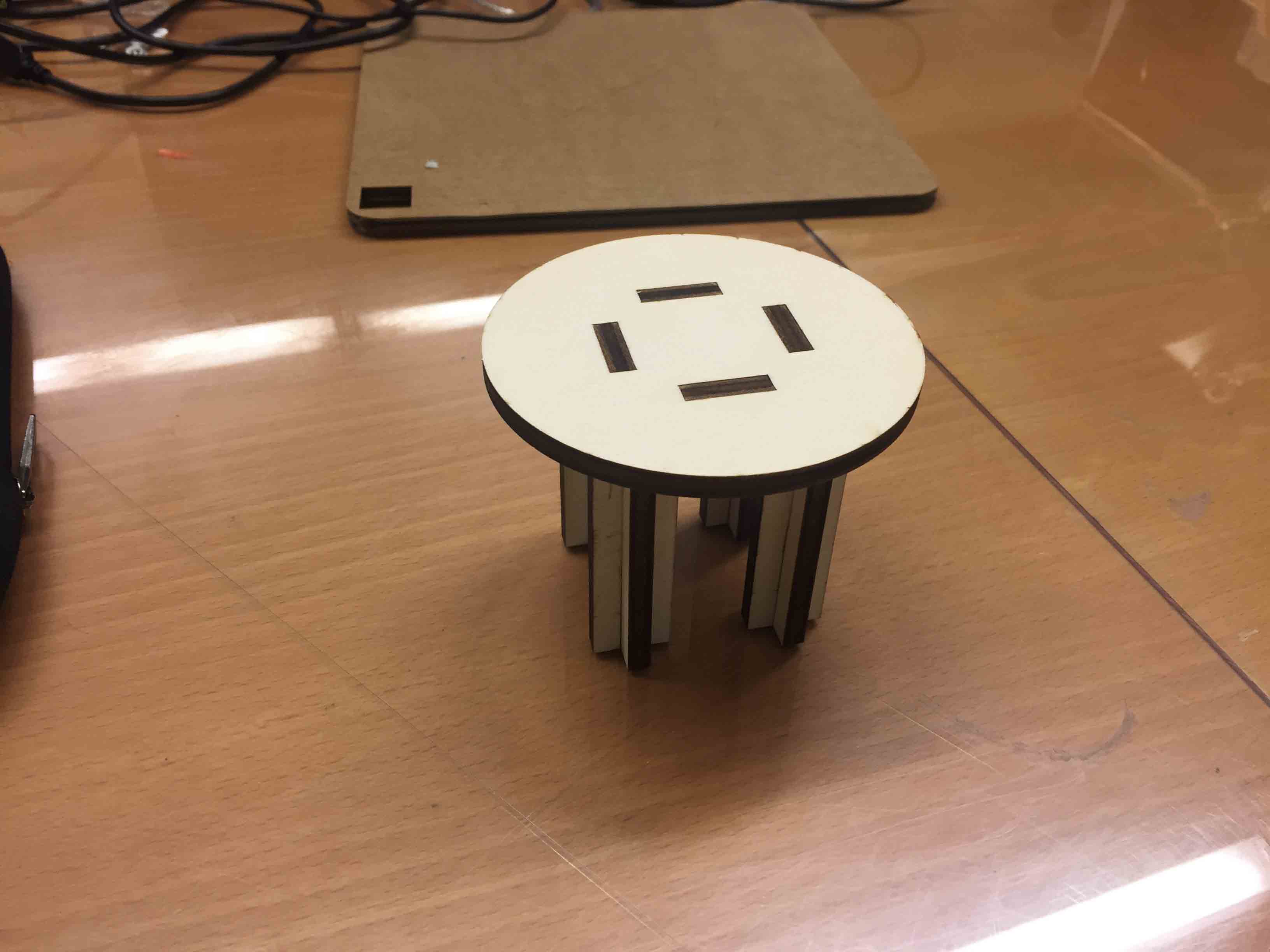
I tried to resize all pieces but I haven't solve my problem. So I have decide to change the table legs, sketching another type of joint but using the same design. This is my new design:
I used the same sketch for the tabletop but I have deleted two holes.
SHOPBOT
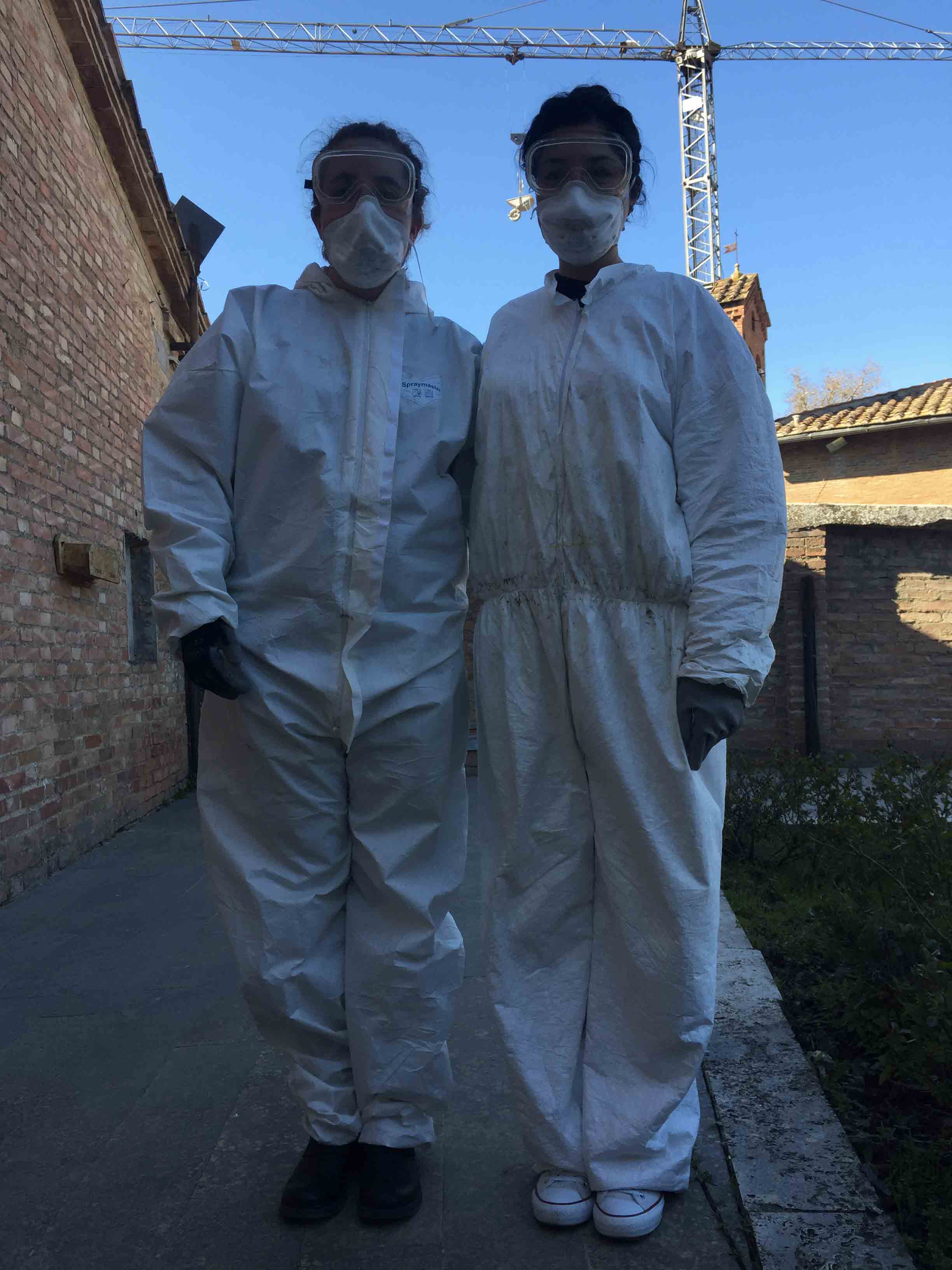
Before describe the process that I have used for the cut, I must spend some word about this machine. This is the most dangerous machine so it is important be careful. You may cover yourself, wear safe glasses, mask and gloves. Ask at someone to help you, it's important have someone who check your work, sometimes you could forget something of important. I have asked help to Silvia Palazzi, my kind classmate :) .
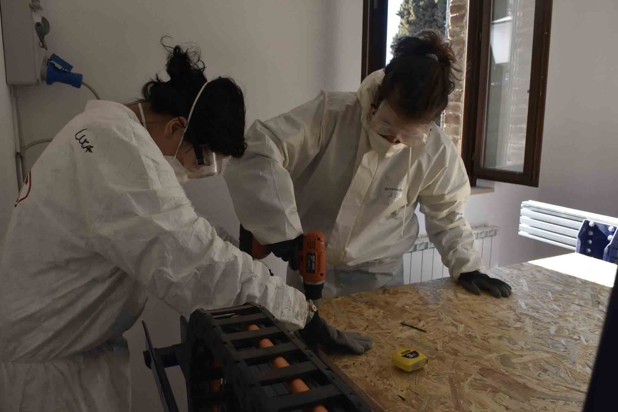
After becoming a ghostbuster, I have fixed with screws my OSB board on a MDF board on the ShopBot machine.
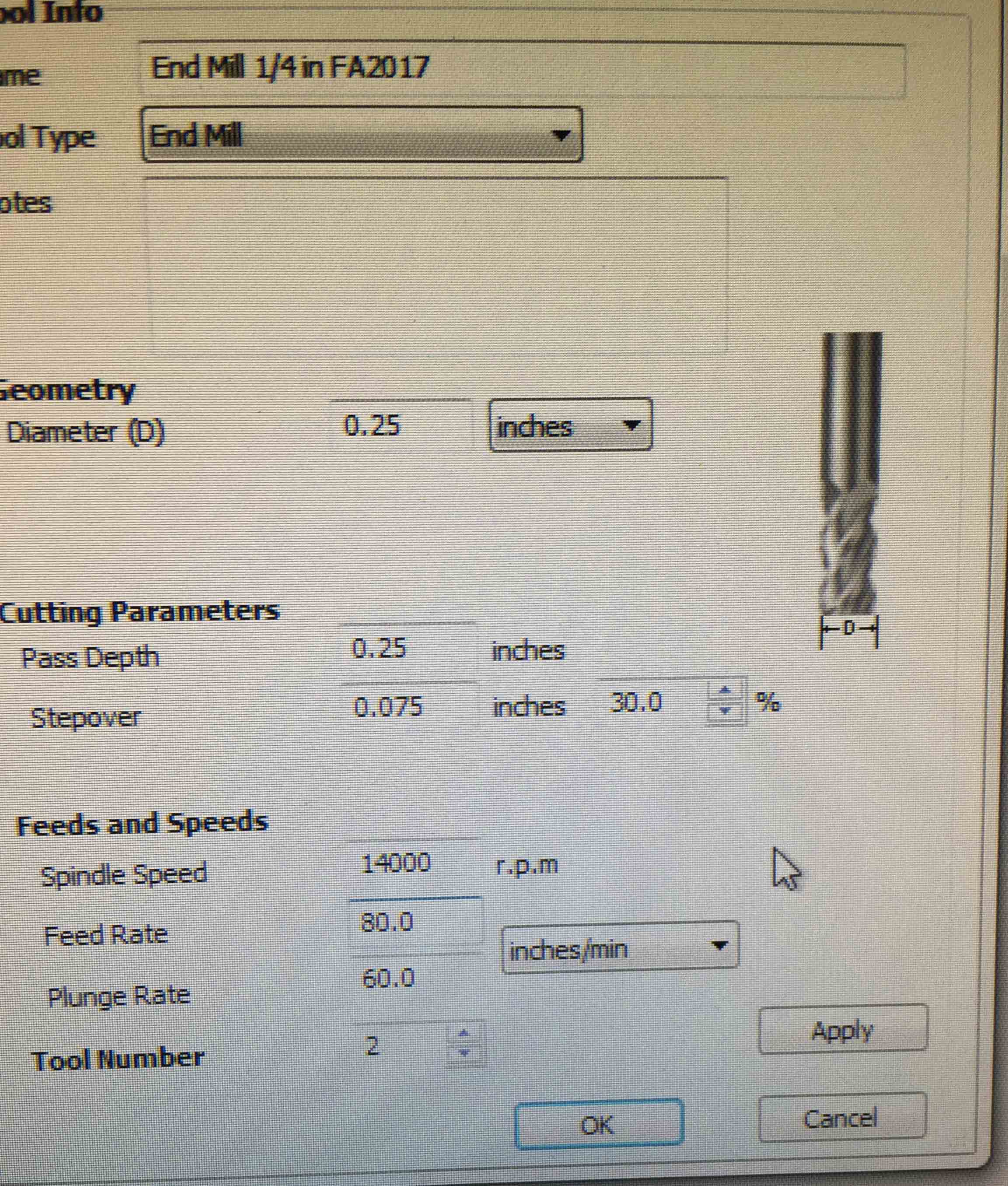
After that I had to calculate the Feed Rate (how fast the endmill moves during the cut). To find this value I had to do this operation:
RPM: "Revolution per minute" of spindle
chip load: It indicate how many materials will be removed during the cut. We can find this value in a table, for each material, who given the dimension of endmill.
cutting edge: Number of cutting profile on endmill
Our result was 192 inch/min but we used a lower value to be sure.
After that I have opened my sketch on Vcarve for creating my toolpath. I started with the pocket.
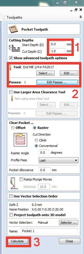
1: I have changed Cut Depth with the height of my material
2: I have selected my endmill and I have set 5 Passes
3: I have pressed on Calculate to create my toolpath file.
After that I have prepared the cut toolpath.
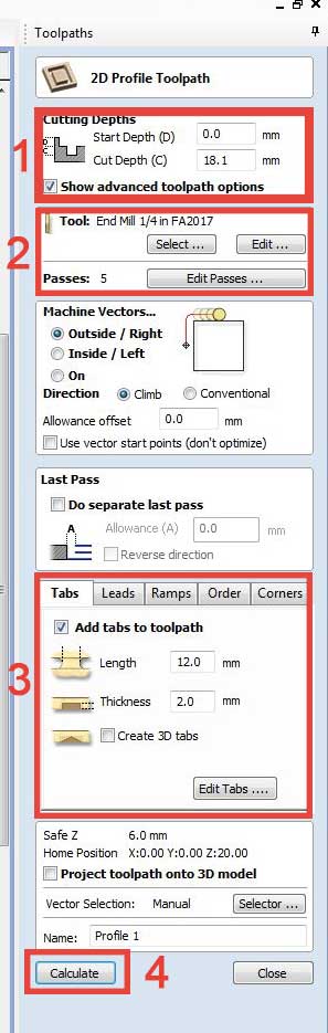
1: Same thing as the pocket. I have changed Cut Depth with the height of my material
2: I have selected my endmill and I have set 5 Passes
3: I have added the Tabs and edited leght and thinkness
4: I have pressed on Calculate to create my toolpath file.
I have followed this workflow two times, one for joints and one for the external cuts. After that I have done some tests with ShopBot for checking that the endmill didn't go up the screws. I have setted X, Y and Z axis on origin.
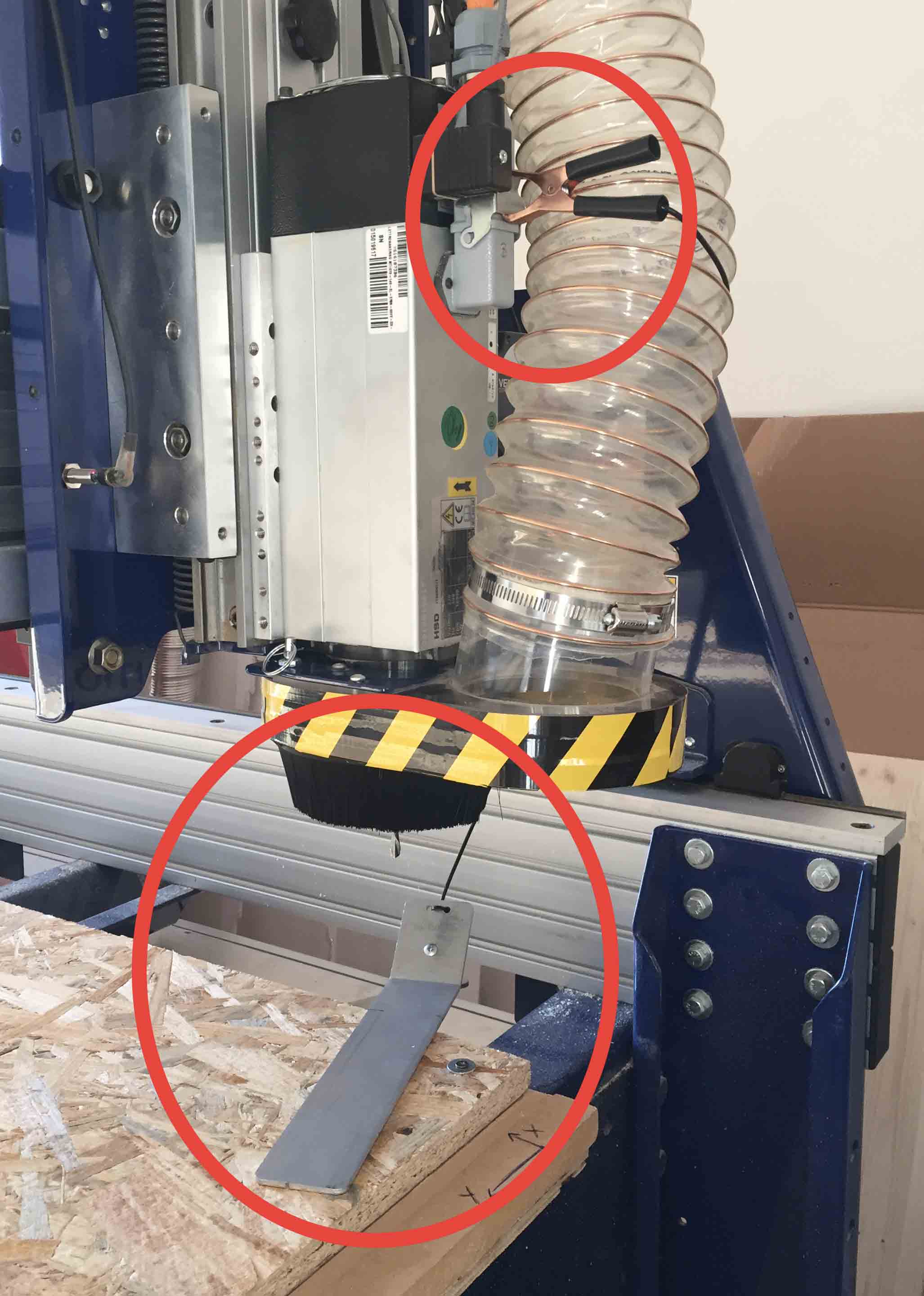
NOTE: To set the Z axis I have used this tool
I had to set alligator clip on circuit-closing spot. I have turning on the aspirator then I started to cut.
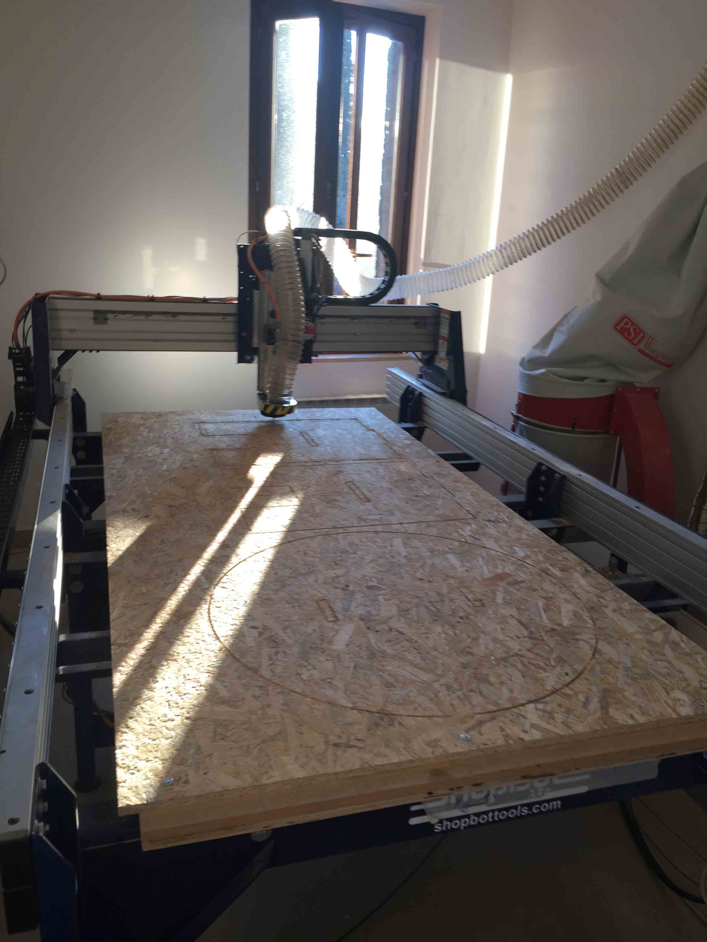
It's most important be focused during the cut, because you must be prepared if something wrong happen. I keep stop button always in my hands. When cutting is finished I had to remove all parts, and at this point I saw a lot of problem in my design:
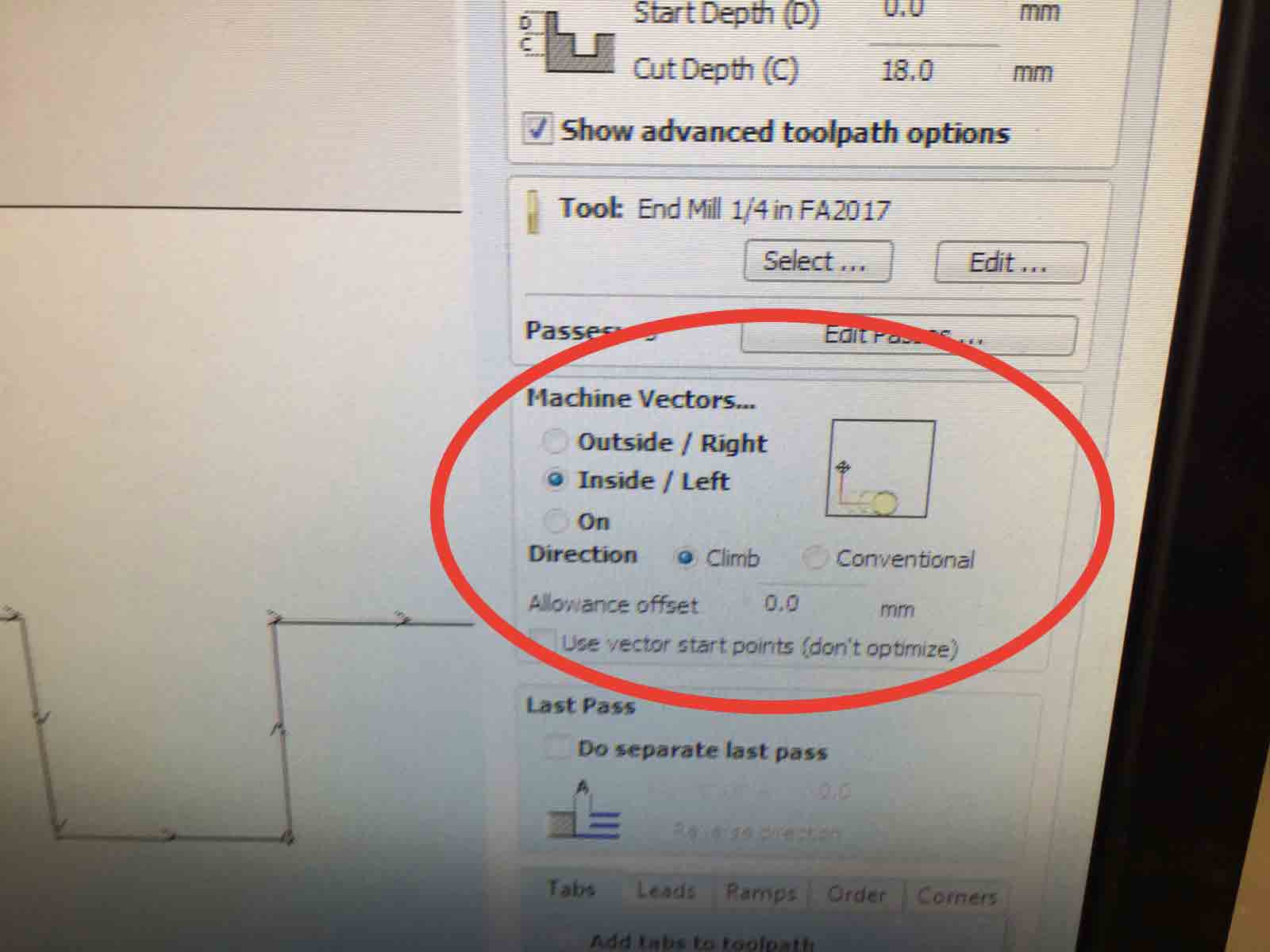
FIRST: Joints was widest as the height of material.
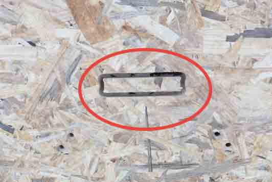
This happened because I haven't set Machine Vectors in the right way. For the inside cuts I had to choose Inside/Left cut, not Outside/Right. Using the wrong set the ShopBot cutted an hole high the hights of material plus the endmill diameters.
SECOND: Slot was 10 centimeters smaller than male joints. In this case was totally my fault. I chose the wrong sketch. During the design process I have done some attempt to find the right way for cut all parts in one board so I have exported the wrong sketch.
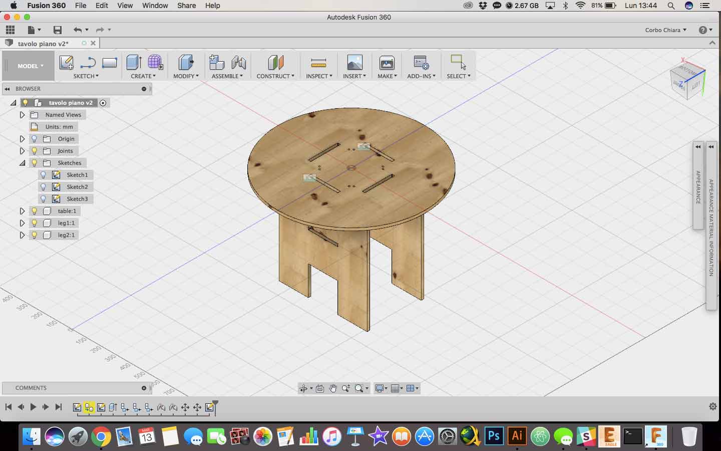
Luckily I have been able to use a bonus piece of board (cause the first error wasn't totaly my fault. My instructor forgot to tell me that), so I have cutted again my tabletop. This time I have checked thousand times before. This is the 3D model of my final table.
I have cutted the tableplane and with the help of Alessandro Alonzi I have assemble it. I had some problems to asseble it because I have used two different woods with different thickness. Joints was smaller 3 millimeters. So with the help of sandpaper and patient, I have tried to widen the holes. I haven't great results, so I decided to chang instrument. Dremmel was the right choise. With it I have been able to smooth in homogeneous way. To insert them I still used an hammer, expecially because I was tired and my arms was distroied. At the end, I have build it and this is the result.
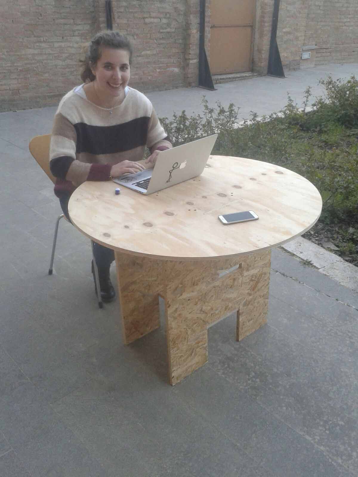
I know that it isn't the most beautiful and stable table in the world, but during this week I have understand which errors I have to avoid during final project development.
SUGGESTION: To avoid all this problem, is always useful do a test cuts. As you can see in my documentation I have done it only with the first model and not with the final one. This cause I put my trust only of the 3D assamble, but it's wrong. If I did a test cut I could have seen all problems without wasting material.
CONCLUSION AND DOWNLOAD
This week was fantastic! One of my favorite at the moment! Too bad for my ugly design, but thanks this week I can say "Bye Bye Ikea!"
You can find all files here

This work is licensed under aCreative Commons Attribution - ShareAlike 4.0 International License.