WEEK 4 - ELECTRONICS PRODUCTION
Introduction
The assignments of this week were:- Make an in-circuit programmer by milling the PCB (program it, so that you can use it to program your board in Electronics Design week, and in other weeks)
- Optionally, trying other processes.
MILLING
For this week assignment we have built a FAB isp . Our instructor have raccomended us to mill the Fab Optimus.
Why Fab Optimus? Because I think that the mini USB connection it's stronger and durable than classic USB.
On FabISP page I had two versions as to choose from.
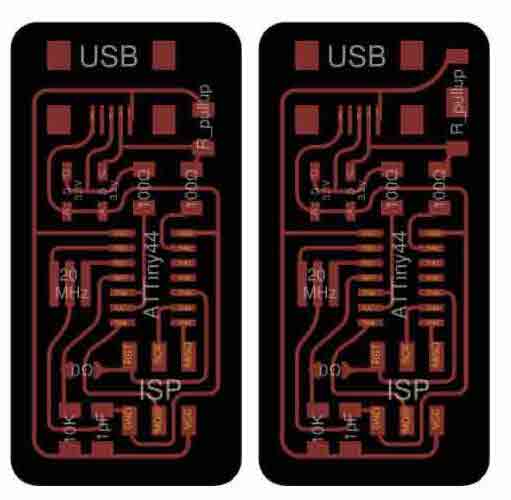
The difference between these two it's that the first one have a 1.5K pullup resistor and the second one have 1.0K pullup resistor and a 0.5 pullup resistor (whose parallel combination is 1.5K). I have chosen the second one because in our inventory we didn't have the 1.5K one. I have downloaded the images
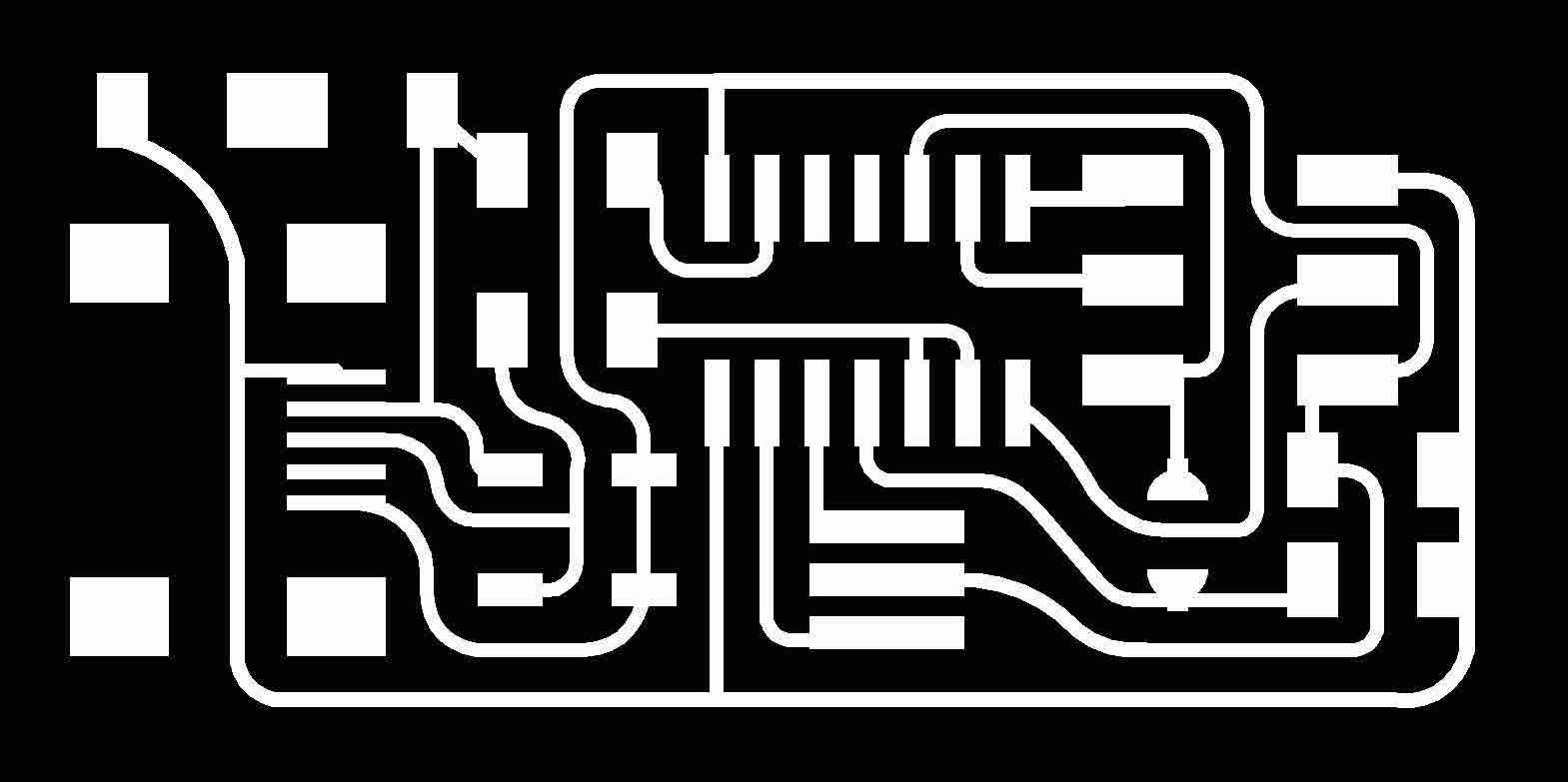

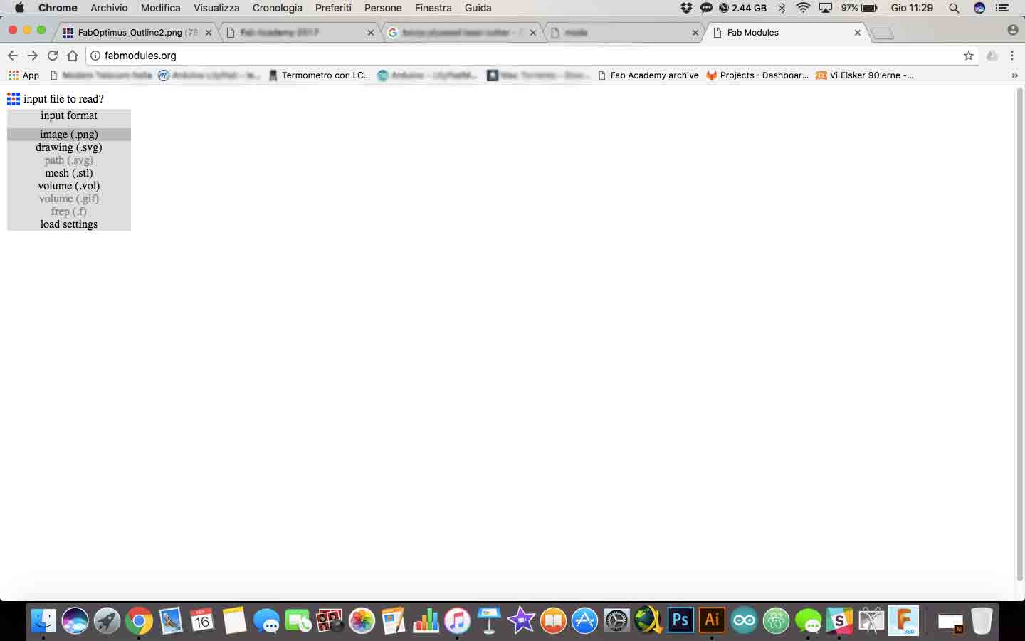
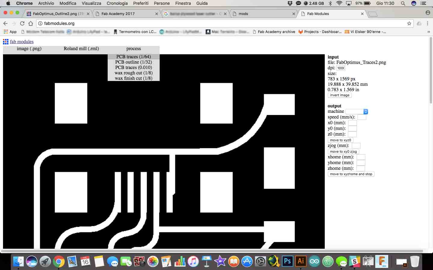
I have used Fabmoduls to generate the files needed for the machine in our lab. I have upload the PNG traces file on Fabmodules
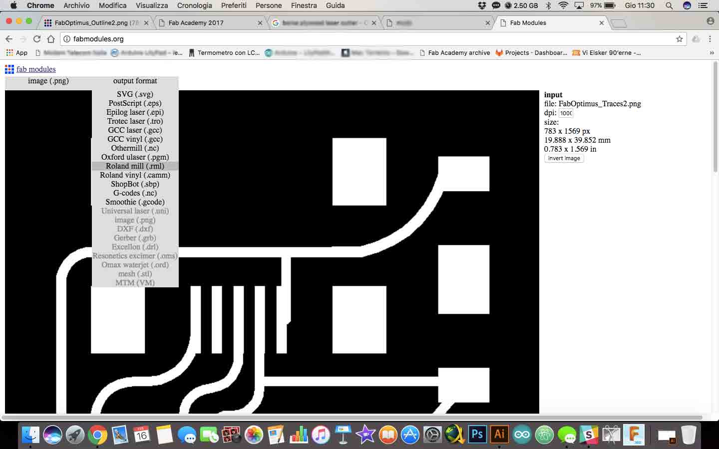
Then I have chosen the right output format. We have a Roland milling SRM-20 in our lab, so I have clicked on RML extension.
After that I have setted traces parameters. The difference is the kind of processing. For mill the trace I must be use a 1/64 inches tip, for outline I must be use a 1/32 inches tip.
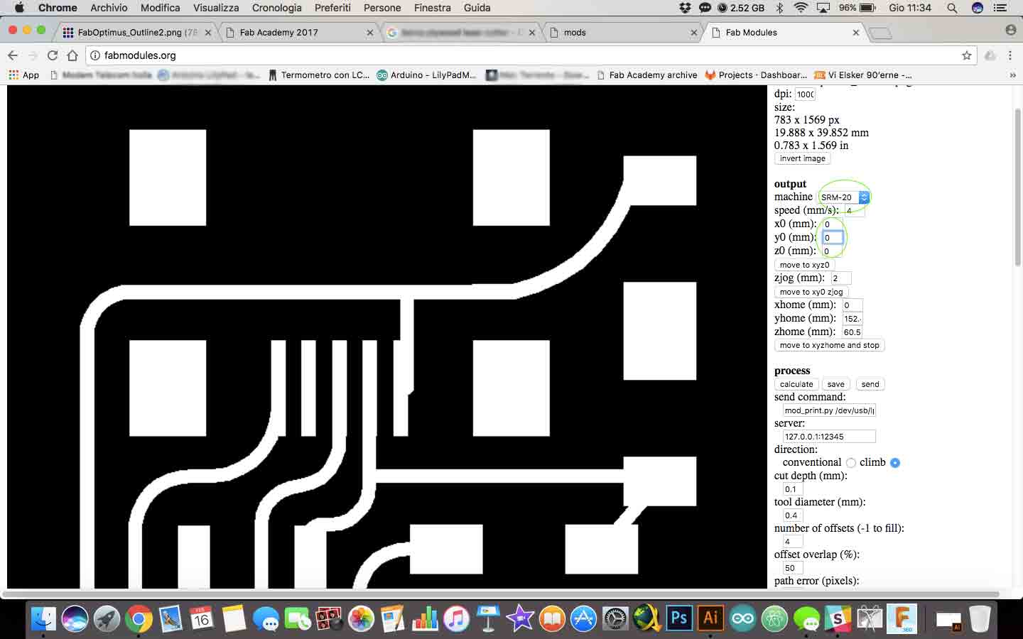
Then I have modified settings in this way:
- model: SRM-20
- x0, y0, z0: I have annulled parameters because I have setted it manually.
At this point I have pushed on calculate button to have a preview of path that the machine would have done. Then I have pressed on save button for download the file (You can find it at the bottom of the page).
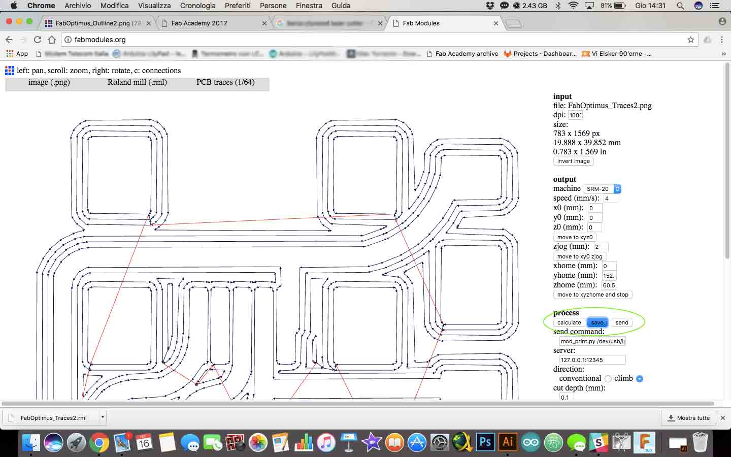
I have followed the same process for outline picture. I have changed only the process value with outline 1/32.
Now it's time to move the files on another computer whit the Roland's software. There is the most important commands, usefull for our work.
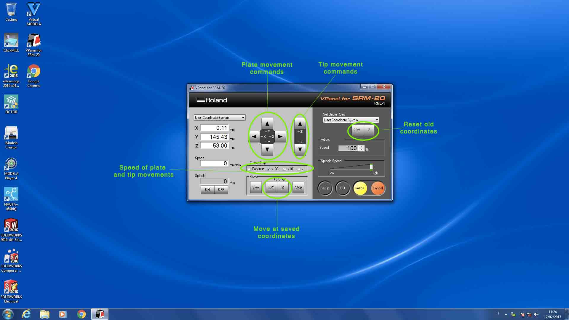
I had to set up X, Y and Z axis parameters.
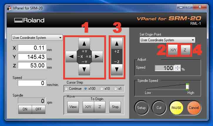
1: With the arrows I can move the work plate in the starting position.
2: By pressing this button I have saved the coordinates.
3: Moving Z arrow I can move the tip. The right position for the tip is 4/5 millimeters between plate and FR4 board.
4: By pressing this button I have saved Z coordinate. But before moving on with milling I had to move tip touches the plate.
After each milling (traces and outline) you can use the same X and Y coordinates but not Z axis. You have to re-set up each time.
I have uploaded my file (I must be started with traces file for ensure that the material doesn't move during the work) then I have pressed Cut button.
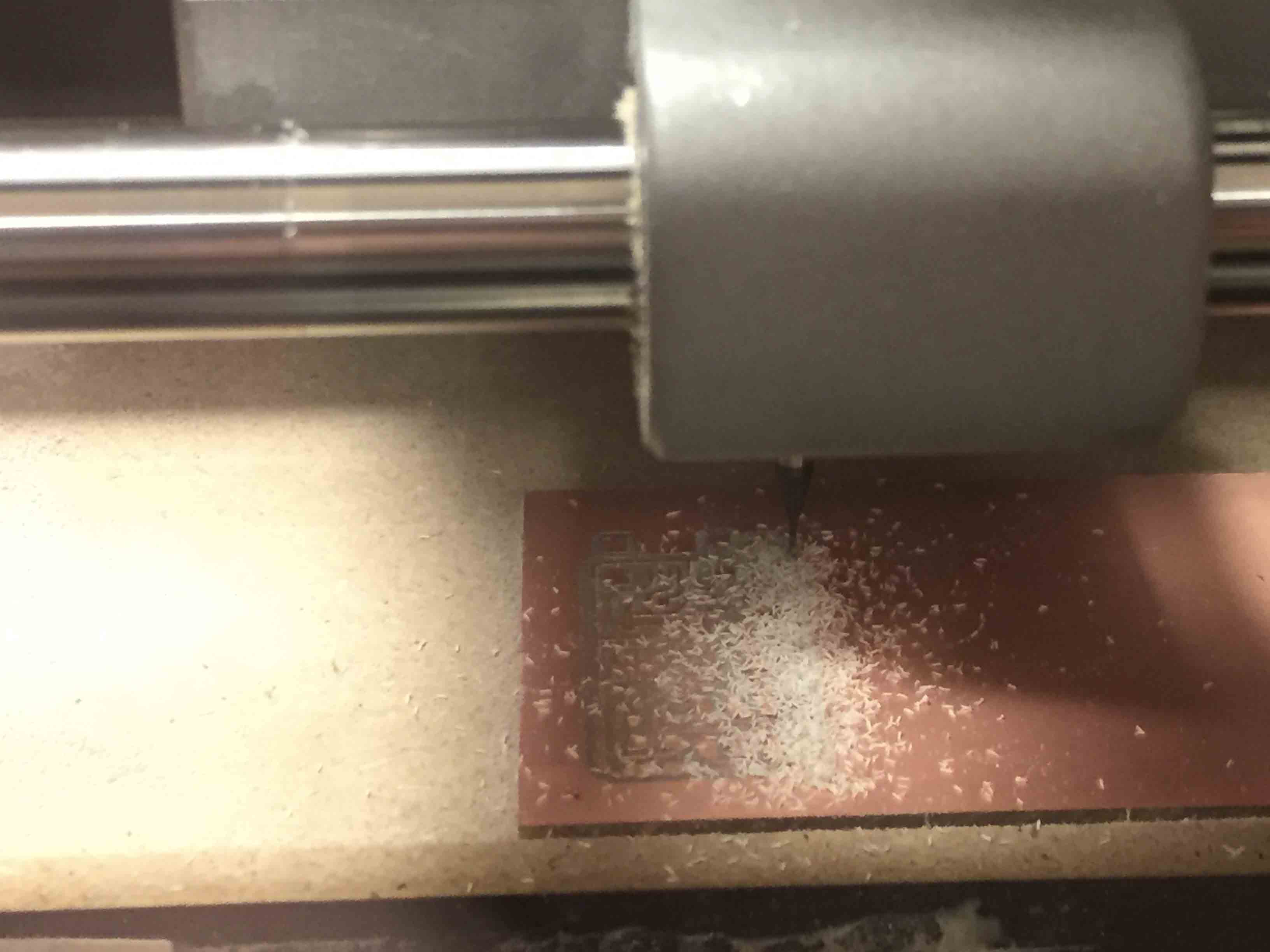
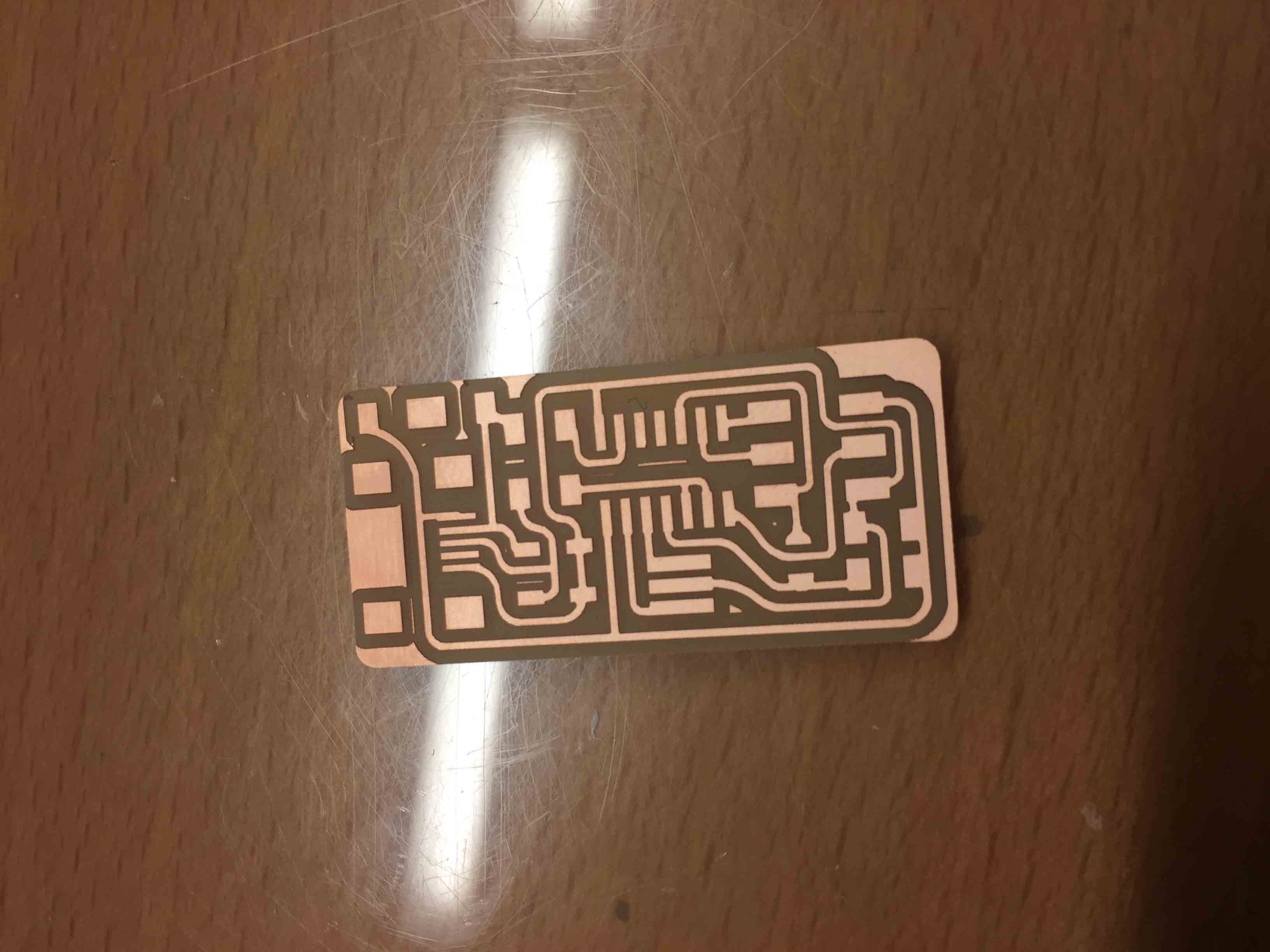
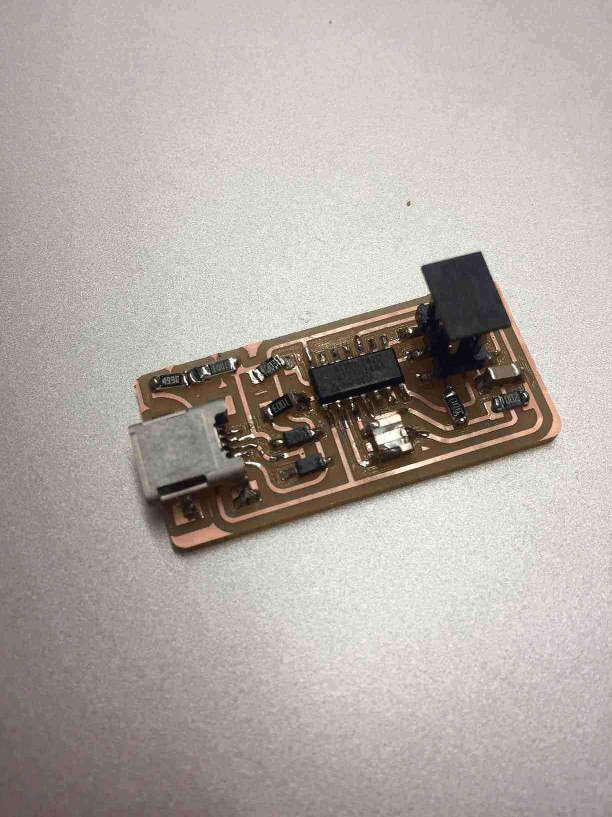
After 15 minutes of work, this is the result.
Now It's time to soldering!
SOLDERING
After milling I have washed my board with soap and water for remove waste material and allow solder material sticks better. Next step was look which components need for my Fab ISP, so I have write down the BOM (bill of materials)
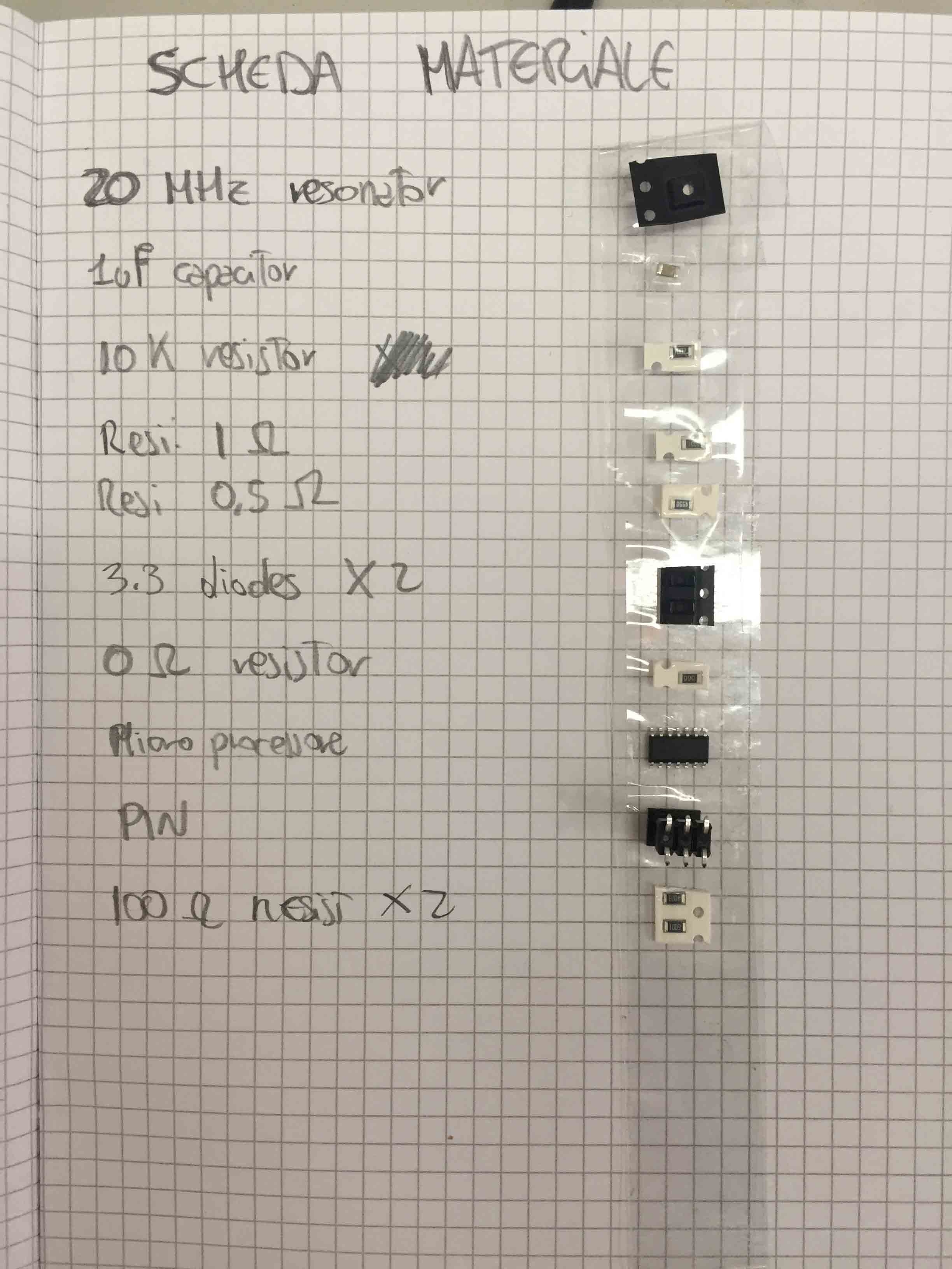
I have looking for all componets in lab inventory and then I have started to solder. I have started with ATTiny44 , the hardest components to solder.
The microcontroller and the diodos have a established position. For understand what is the right position, on this components you can find a point (for microcontroller to sign VCC pin) or a line (for diodo to sign CATODE pin).
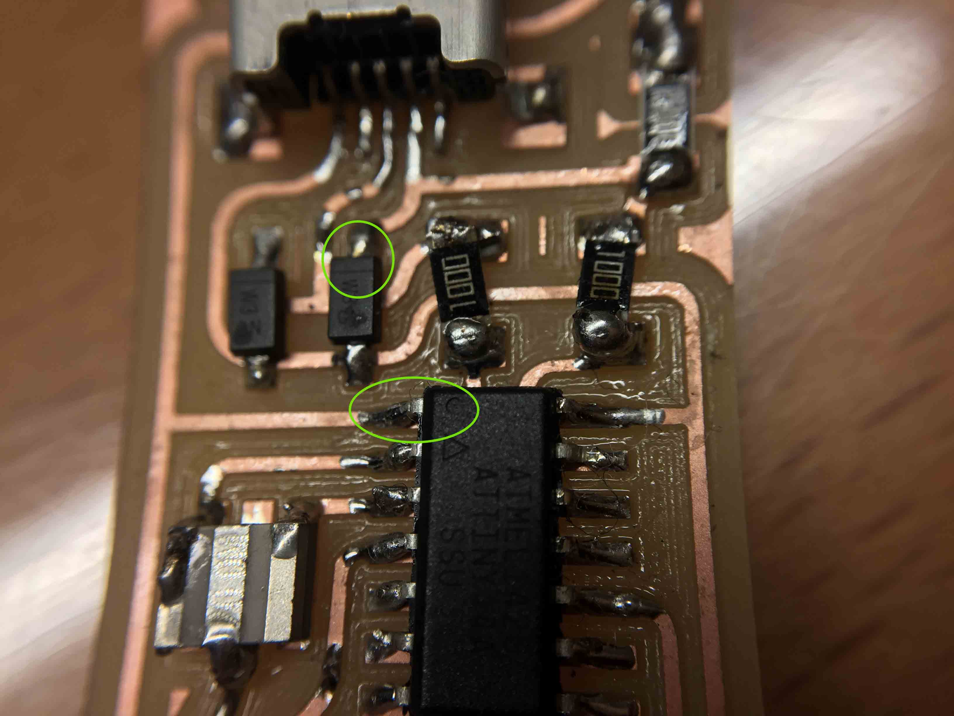
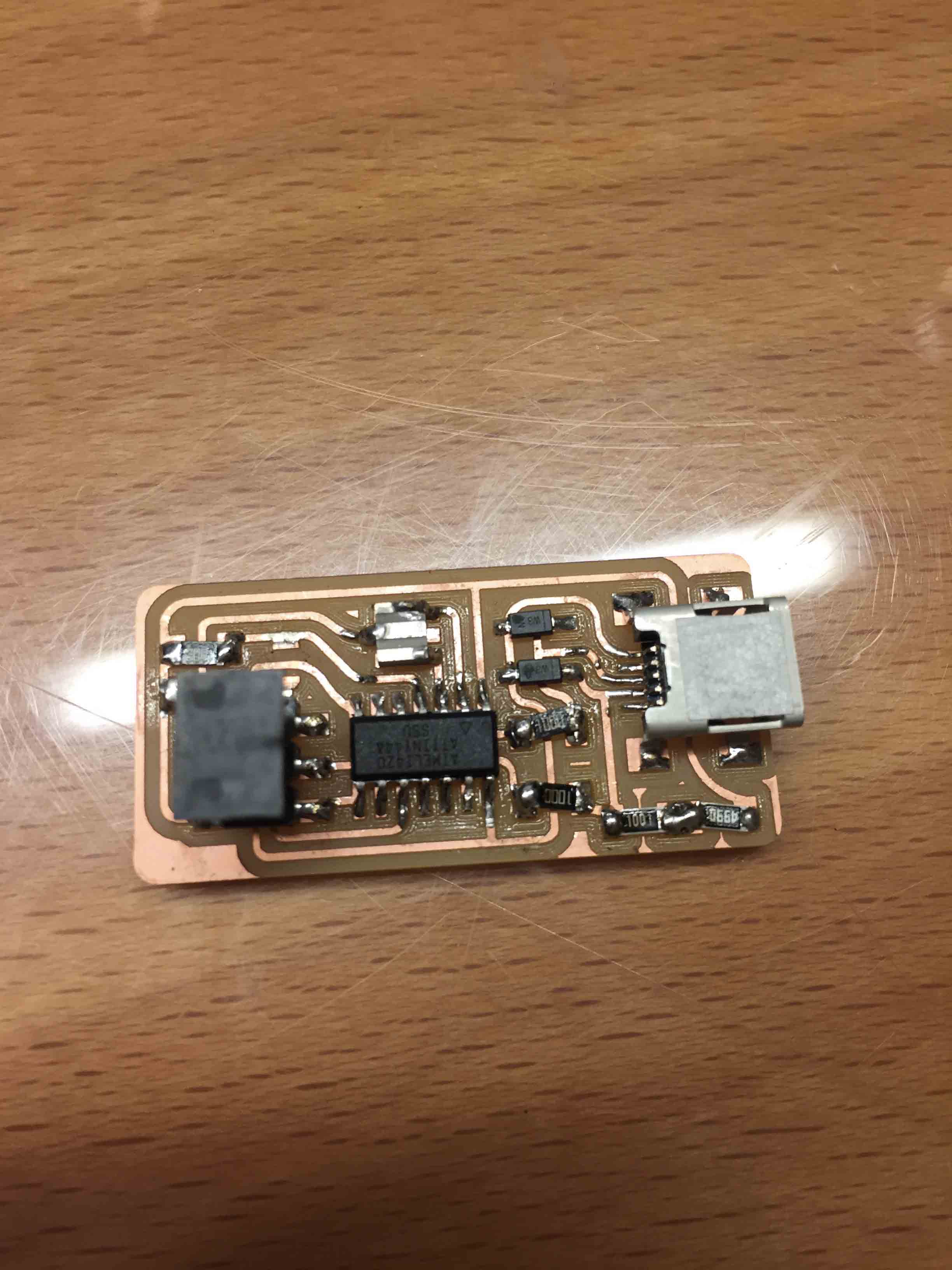
After 2 hours of work I have solder all components and this is the result. It isn't beautiful to see but it was the first time for me.
PROGRAMMING
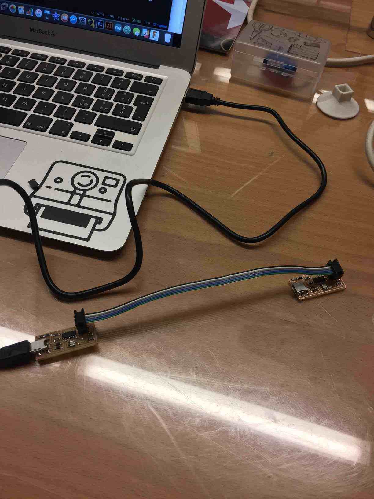
After that it's time to programming it. For doing it I have followed this tutorial. I have a Mac OS, so I have followed steps for it. I have downloaded FabISP firmware (download it at the bottom page) and then I have unzip it on my desktop. For programming it I need to use another programmed board for attach it at mine.
I have followed this step to procede:
- Edit Makefile - I have changed file in this way:
 AVRDUDE = avrdude -c usbtiny -p $(DEVICE)

                    #AVRDUDE = avrdude -c avrisp2 -P usb -p $(DEVICE)
- Open directory who have saved modified firmware:
cd Desktop/fabISP_mac.0.8.2_firmware
- Then type:
make clean
I had this response:
- Second step is type:
make hex
I had this response (under blue circle):
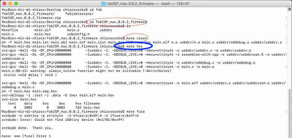
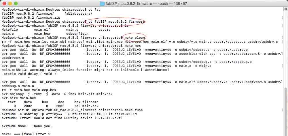
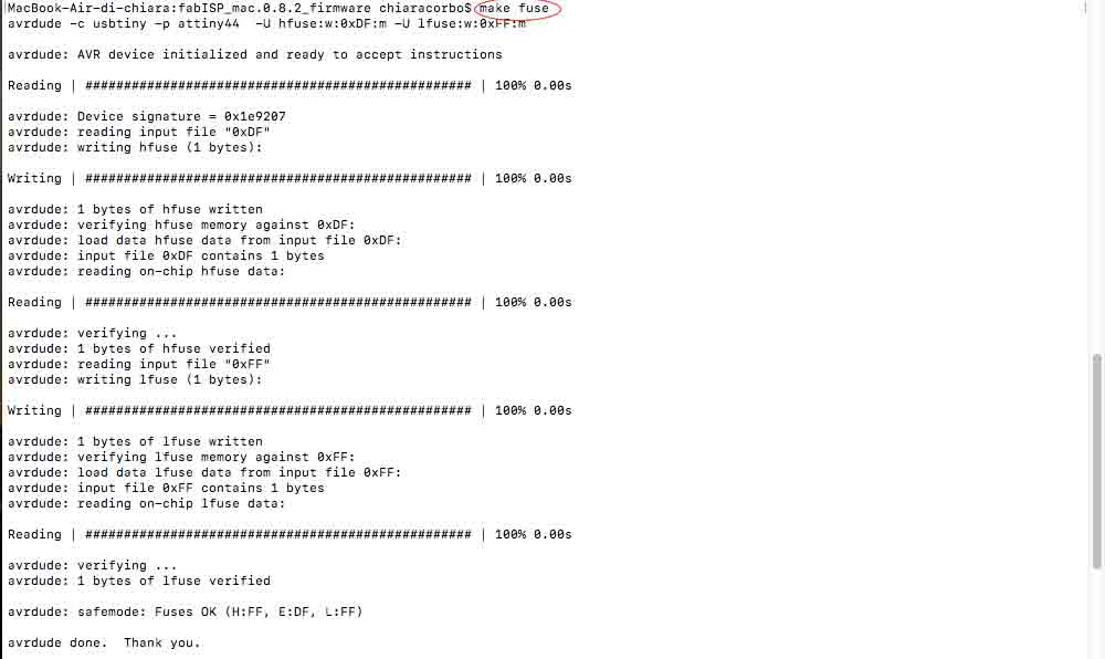
- Third step is type:
make fuse
I had this response:
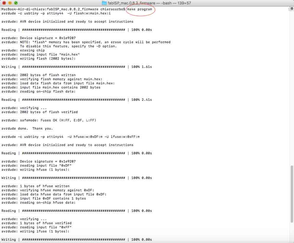
- Fourth step is type:
make program
I had this response:
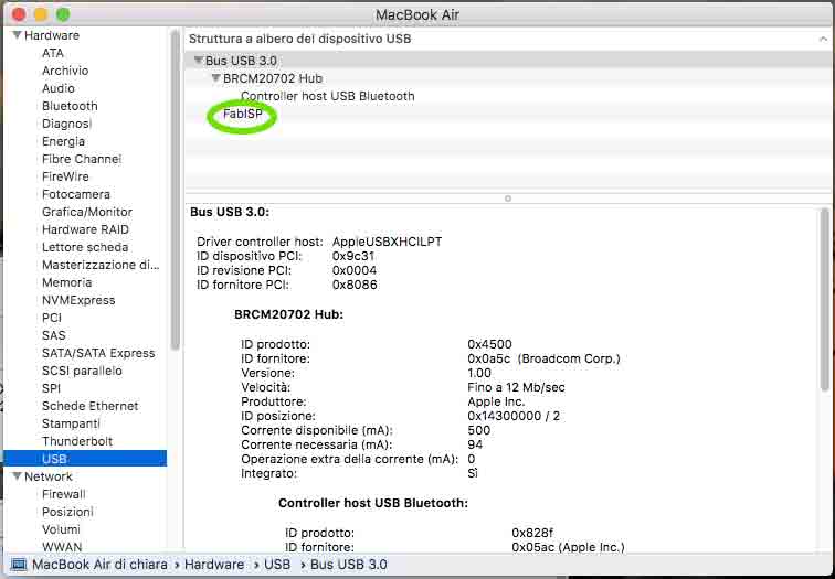
Now it's time to test it, check if your pc recognises the board. First of all I have removed 0Ω resistor then I have connected it at my pc with a cable. I had a problem: My computer haven't recognised it. I've checked my board with a multimeter.
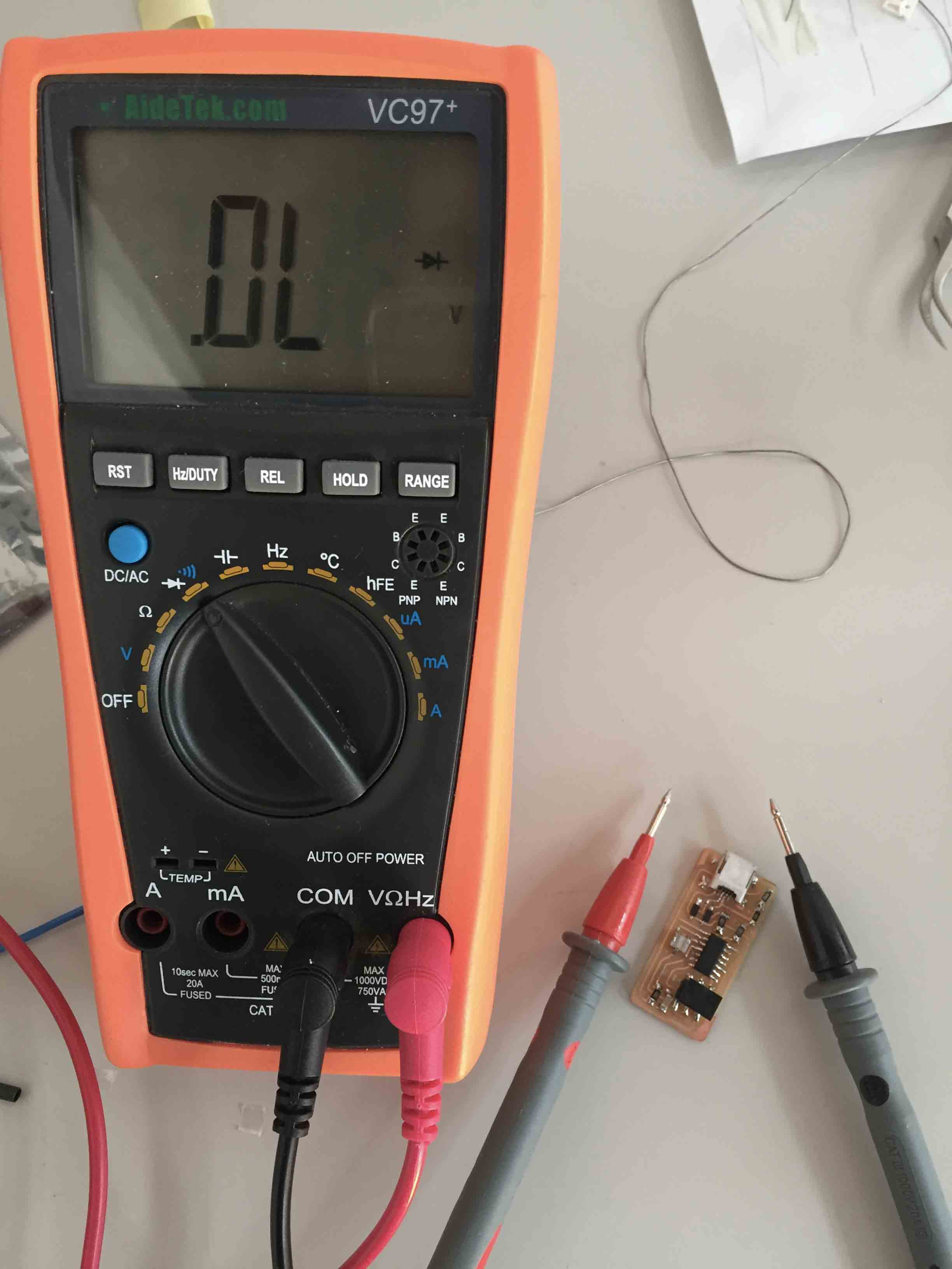
With it I have founded a problem with a resistor solder. I have fixed it and I have done another checkup. Now every solder works but the I haven't fixed the problem. With an help I have understand the problem. I have solder the wrong resistor, so I have changed it.
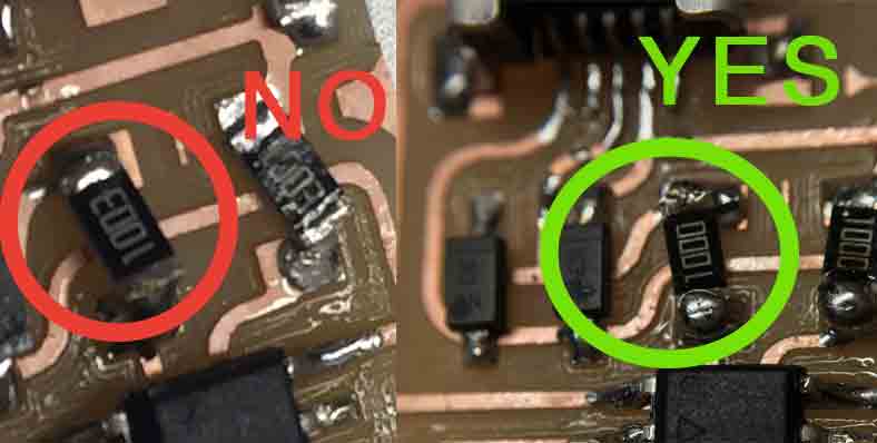
Now I have done another test with multimeter and all solder works, so I have tested it connecting the board at my computer and...now it works!! YEAH!!
DOWNLOAD
You can find all files here.

This work is licensed under aCreative Commons Attribution - ShareAlike 4.0 International License.