Introduction
The assignment of this week was:- Add an output device to a microcontroller board you've designed and program it to do something
STEPPER MOTORS
Before starting to test output devices, I have spent some time to study what stepper motors are and how they works. For our machine we have to use four steppers motors, so our instructor suggest us some tutorials to read.
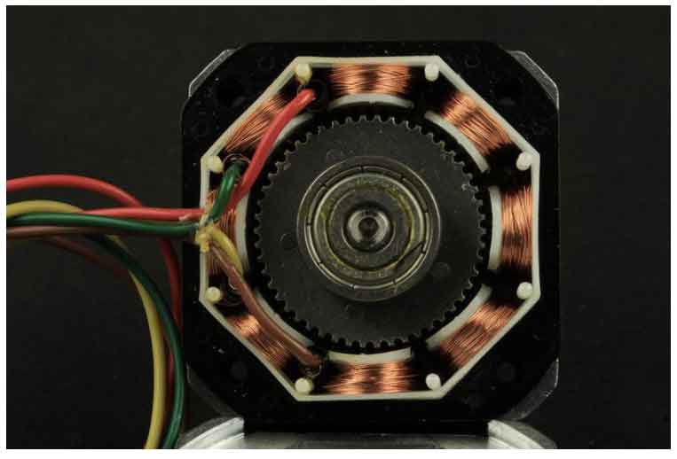
This picture showed how it looks inside. They have a multiple coils that are organized in group called "phases". By energizing each phases, motor will rotate step by step. There are different sizes and styles and electrical characteristics. For our project we will use the same motor of 3D printers.
STEP COUNT
Each motors have different number of step per revolution. Range is from 4 to 400. We use a stepper motor with 200 step of revolution. Understand this value will be useful to calculate how many steps my motor must do to make a complete revolution.
COILS
A stepper motor may have any number of coils. But these are connected in groups called "phases". All the coils in a phase are energized together. There are two different way to energized coils.
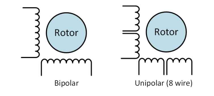
UNIPOLAR motors always energize the phases in the same way. A lead will be always positive and the other always negative.
BIPOLAR motors alterning the phases polarity, so all coils can works at the same moment. A two phase bipolar motor has 2 groups of coils. A 4 phase unipolar motor has 4. A 2-phase bipolar motor will have 4 wires - 2 for each phase. Some motors come with flexible wiring that allows you to run the motor as either bipolar or unipolar.
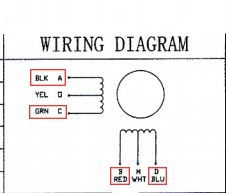
It's important to know what represents each cable. To understand it I have used the datasheet.
CNC BOARD
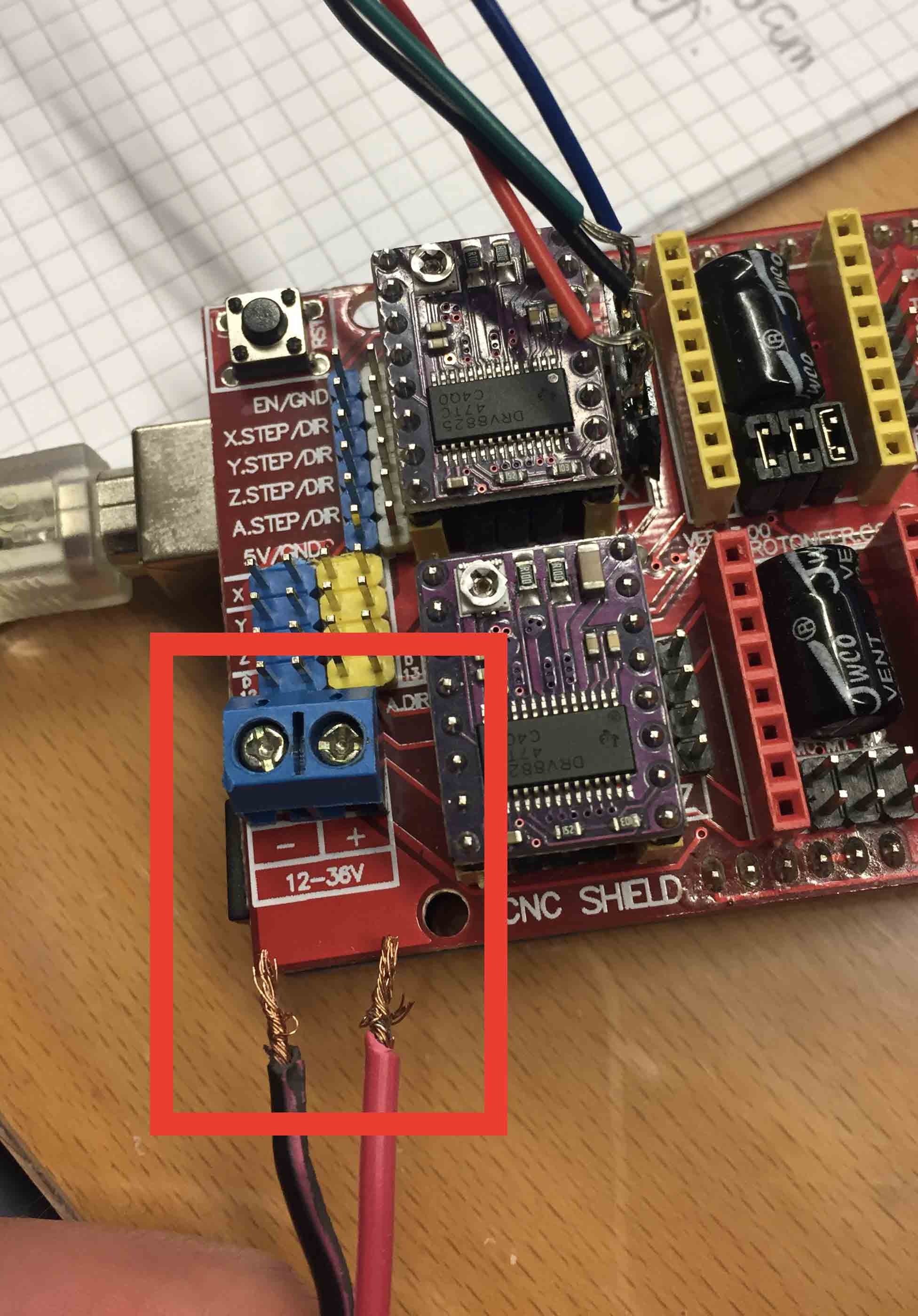
To use this stepper I chose the cable that I have underlined in the picture. I chose that one because they allow me to rotate motor clockwise and anti-clockwise. After that I had to solder a female connector at the cable and then I have connected it on my CNC board. Cable didn't have any order.
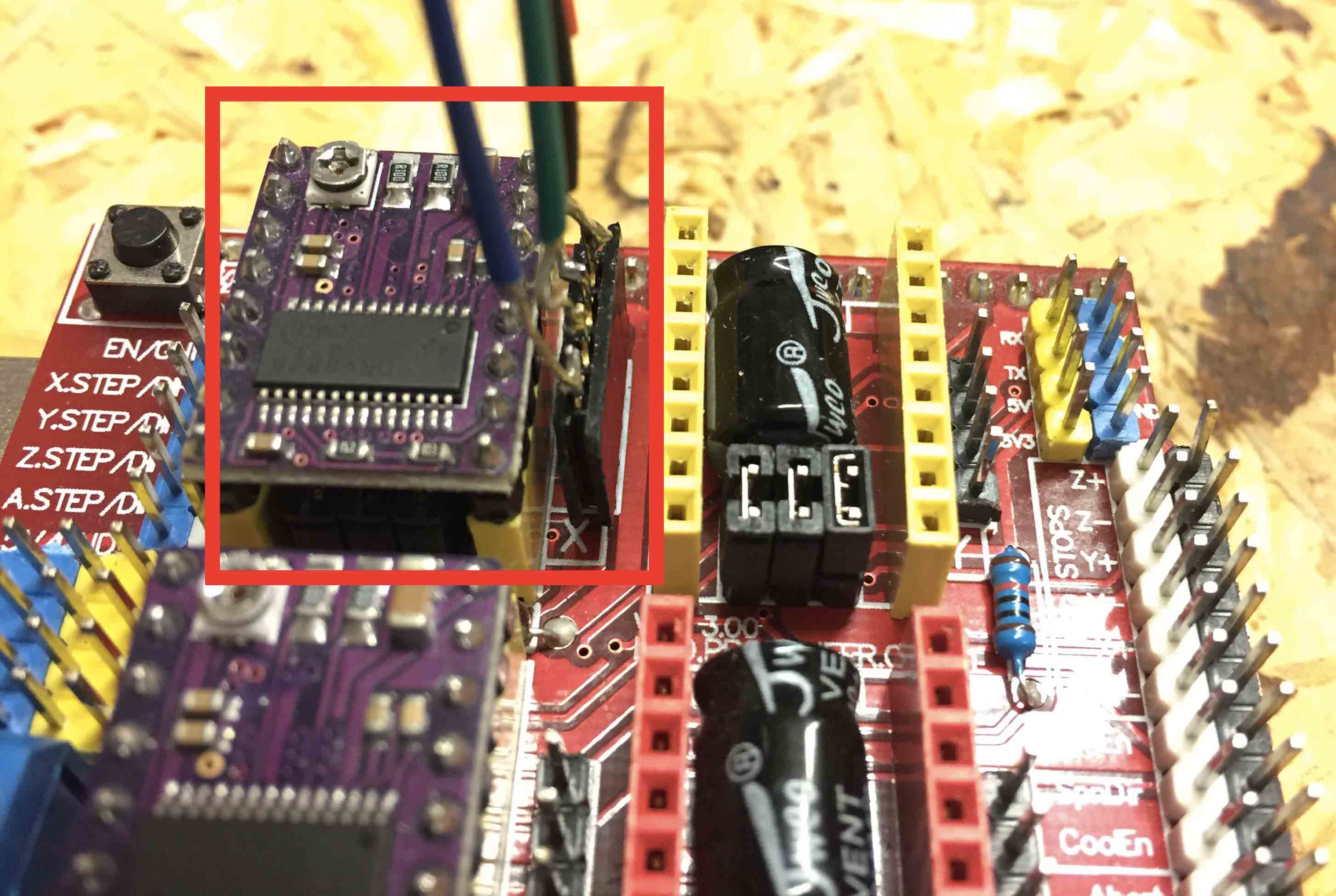
As you can see in the picture, on my CNC there are a stepper driver. I need of it to move my motor and to uploaded the code. This is a schematic of stepper driver.
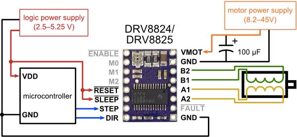
The CNC board require of an external power supply so I used one to 12V. The CNC board works with a power range from 12V to 36V. Red cable is positive and black cable is negative.
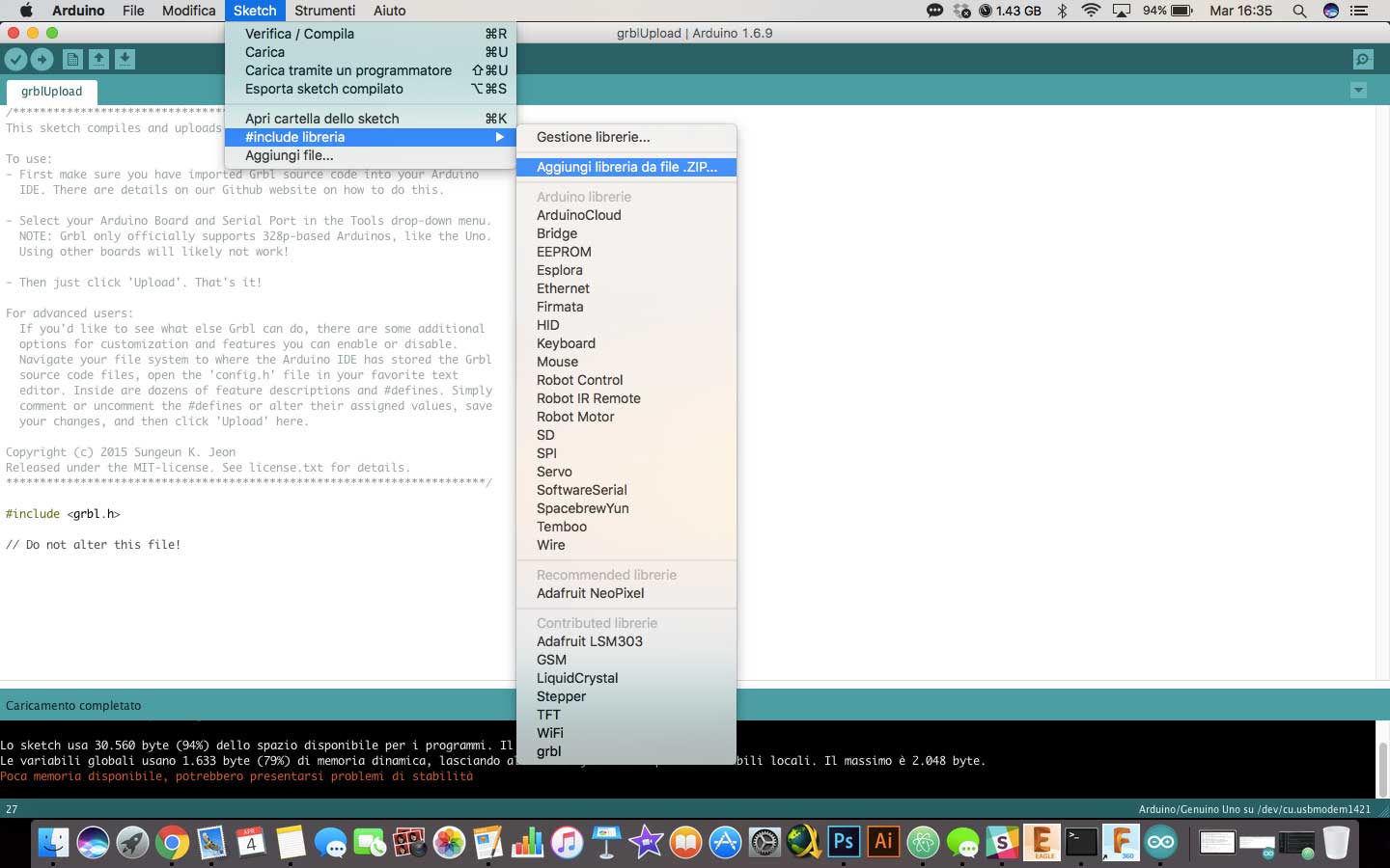
Hardware is ready, now it's time to prepare the software part. First of all I have downloaded GRBL Library. GRBL is very useful open source software for controlling the motion of machines. Most of 3D printers or other open source machine works with it. It works with Arduino's IDE so to upload it as library, I have followed this tutorial from GRBL's page.
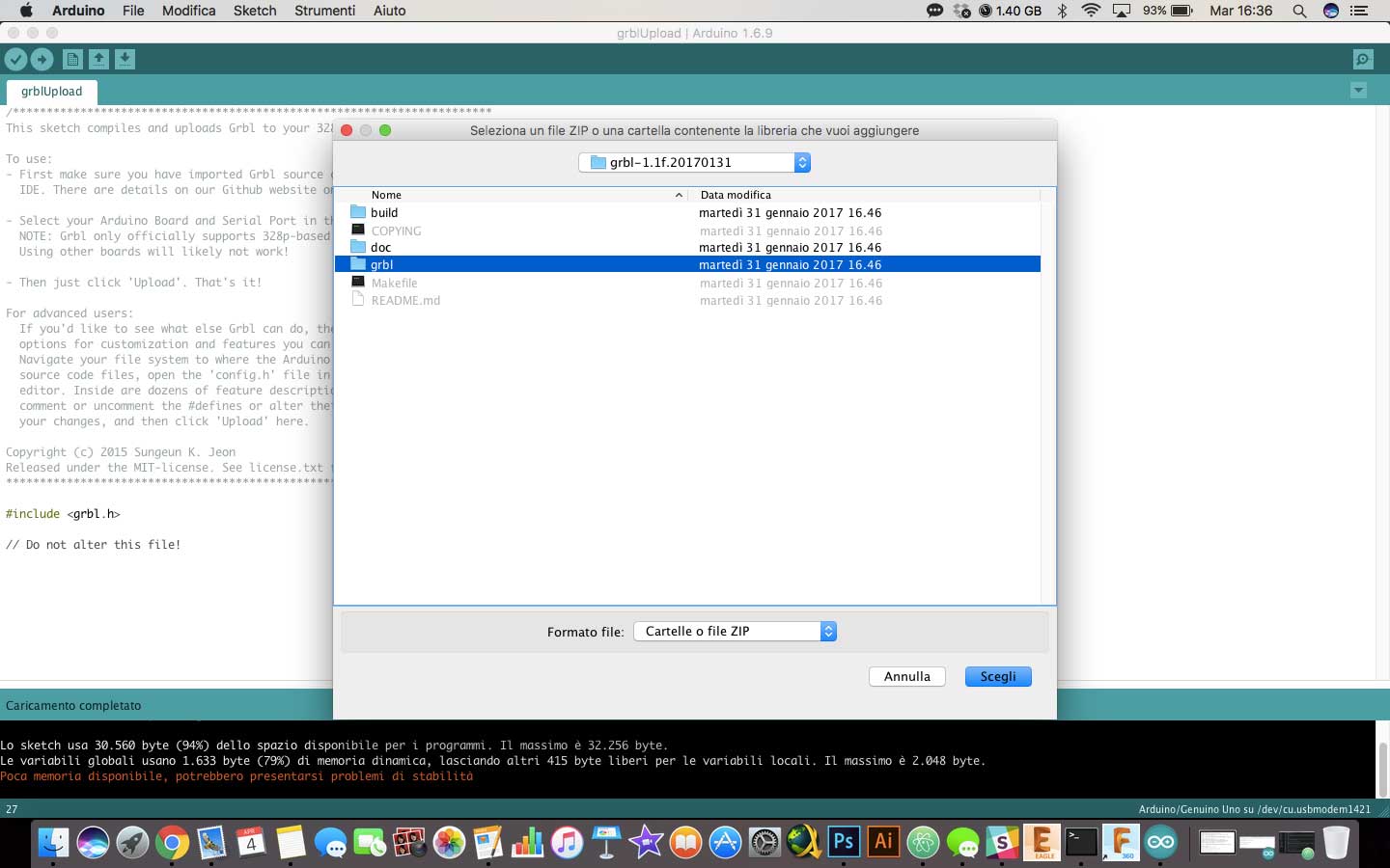
- I have downloaded all zip files and then I have unzipped it.
- I opened Arduino's IDE and then I added the library following this procedure
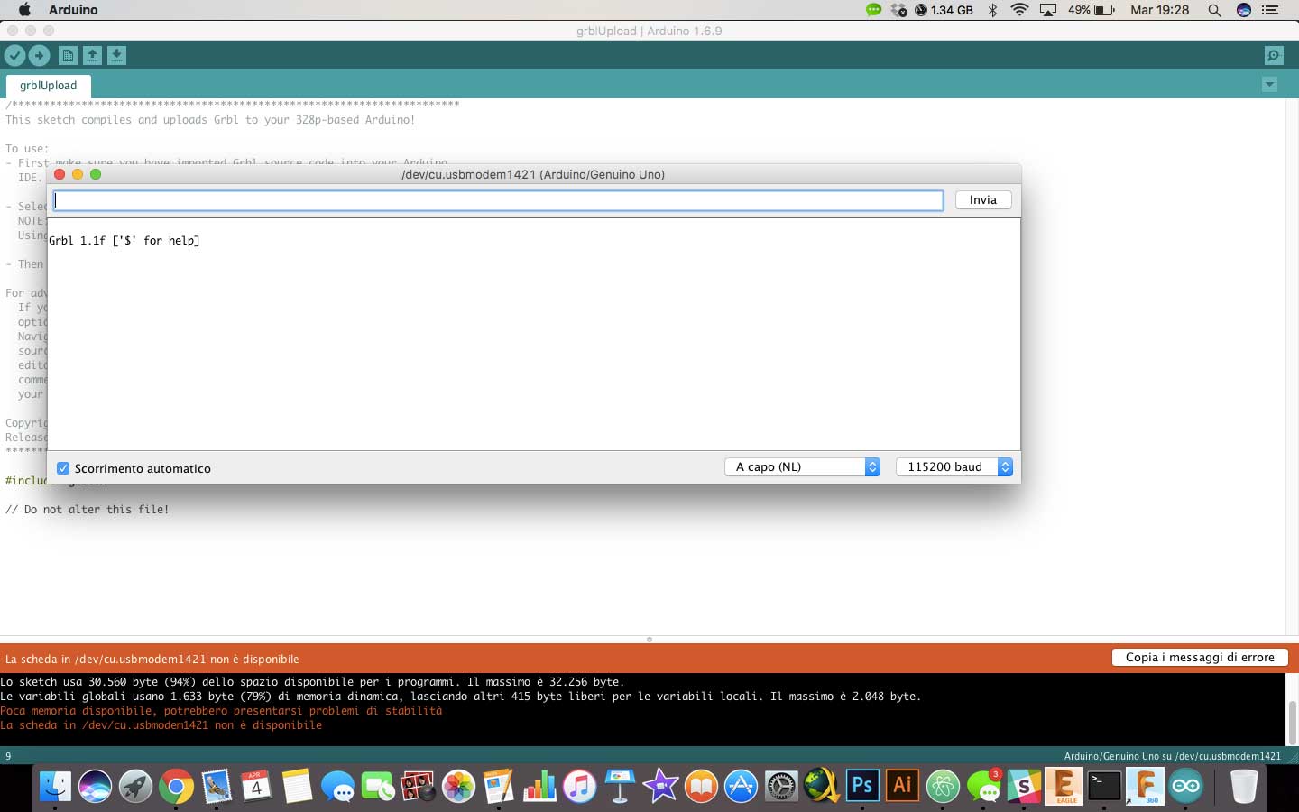
- Then I opened GrblUpload to check if Arduino's IDE recognises the library. It is an example.
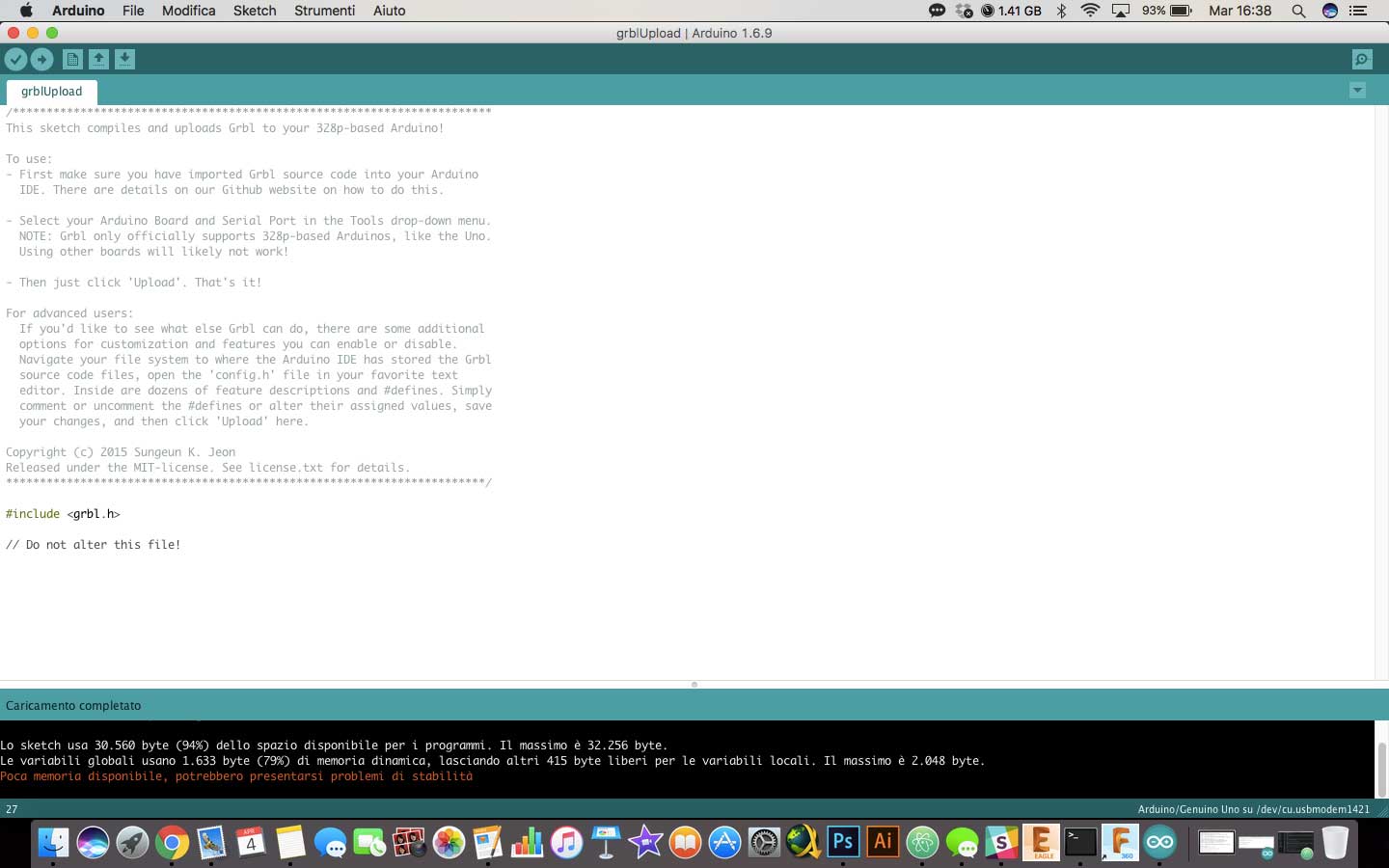
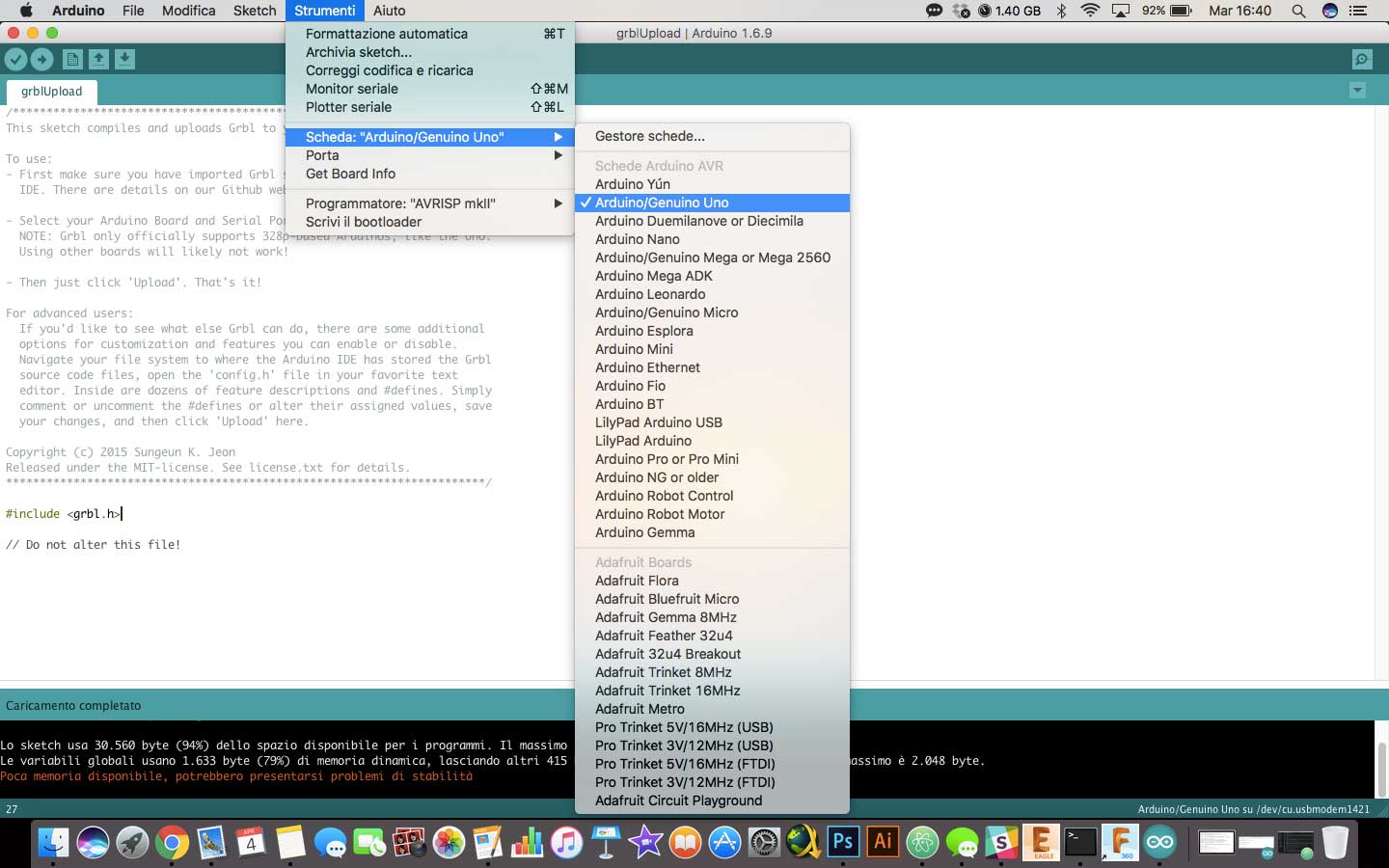
- After connecting Arduino to computer I had to select the correct board and serial port.
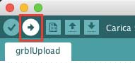
- Last step was uploader GRBL on Arduino with Upload button.
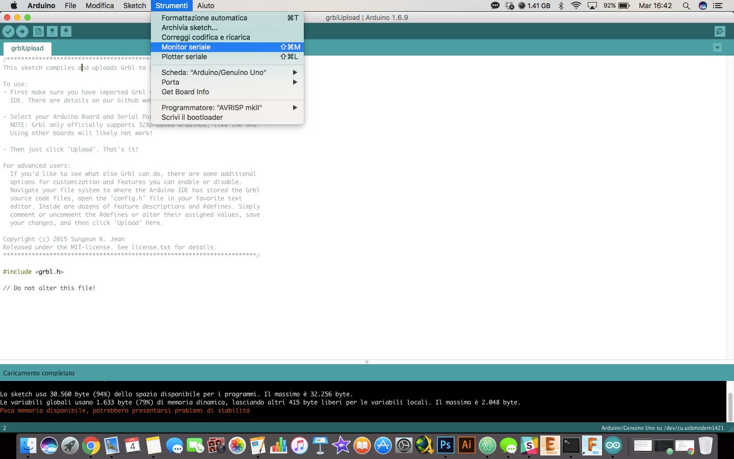
At first attempt motors didn't work because baund was low. Baund value is correspond at comunication speed from software to hardware. Default value was 9600 bound but I've setted it at 115200 bound.

Software work, but I didn't have any output. I checked the connector and I found the problem. Solder were weaker. I fixed them and then stepper works.
Movement wasn't linear but I haven't found right setting yet.
G-CODE
After stepper motors I spent some time to read how G-Code works. It was useful to know because I will use it to program motors for our machine. I found this tutorial clear and useful for a beginner.
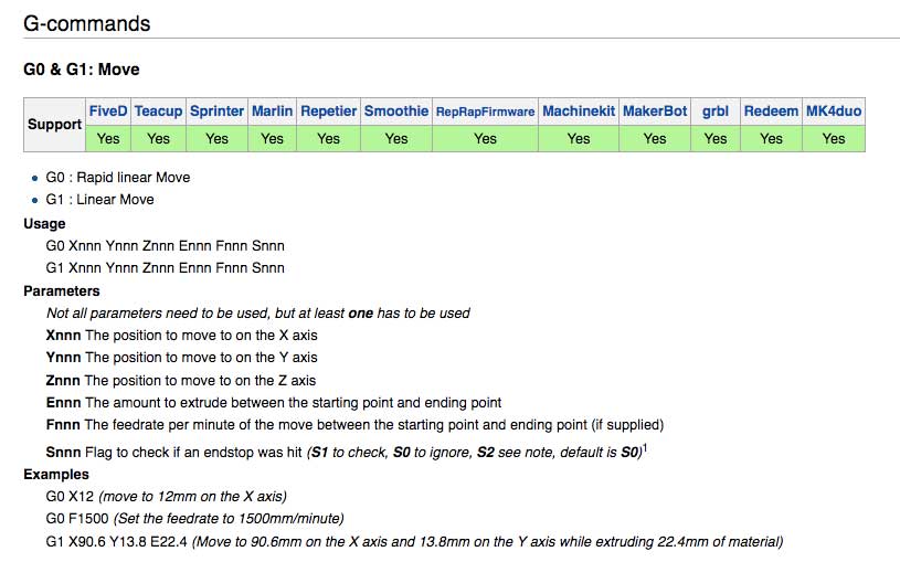
It describe the function of every command and told me if a particular command was supported or not by GRBL.
RGB BOARD
In addition to stepper motors, this week I've tried to build LED RGB board. Using Neil's board I have drawn my own. The RGB LED it is a 3-in-1 components, so each LED needs of your own resistance. To understand which were the right one I have used this site. So basically it needs to 3 microcontroller pins (one for RED, one for GREEN and one for BLU, and obviusly the fourth to VCC). So I have redraw it on Eagle using Neil's board like example.

This is my board.
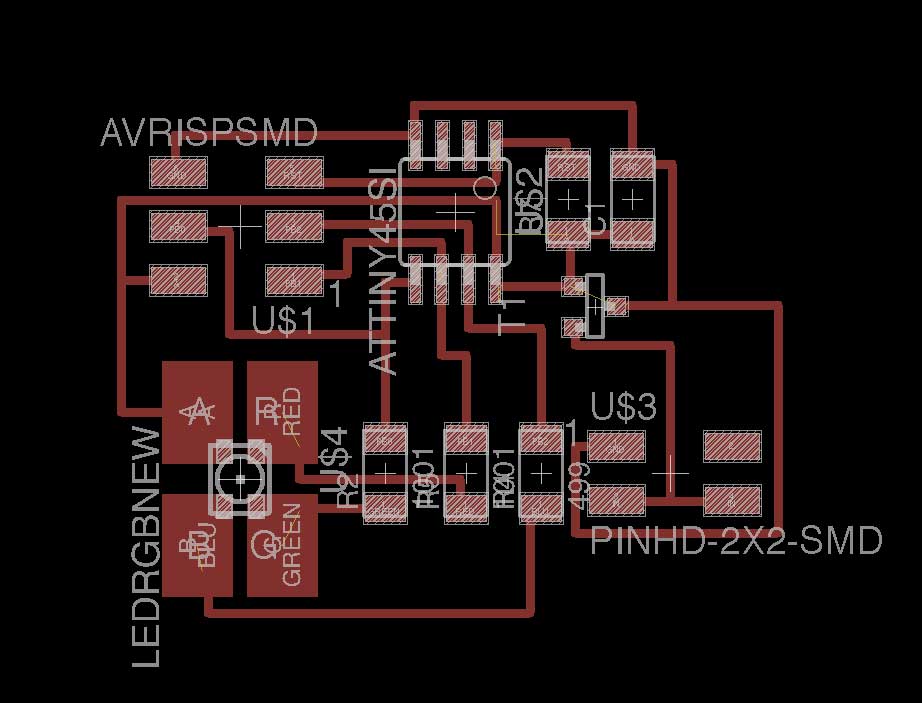
As you can see in the picture LED pad are to big. Probably it is a different LED but it was the only one who had this LED position. In the Fab library who I had installed on Eagle, I had two RGB LED:
The NEW one
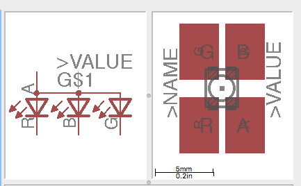
and the OLD one
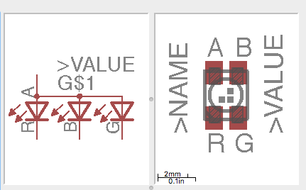
As you can see they have a different LED position, and I have tried to design a board with the smallest one, but haven't been able to connect everything correctly. Then I've decided to use the right component with bigger pad. I've created traces and outline files with Fabmodules then I have milled and soldered it.
At the end I have uploaded Neil's code on it to see if it works.
Then I tried to do my own sketch, I have wrote in with Arduino IDE, not with C because it is most complicated to me.
const int green = 0;
const int blue = 2;
const int red = 1;


const int delayTime = 20;

void setup() {

  // Set digital pin as OUTPUT
  pinMode(green, OUTPUT);
  pinMode(blue, OUTPUT);
  pinMode(red, OUTPUT);

  digitalWrite(green, HIGH);
  digitalWrite(blue, HIGH);
  digitalWrite(red, HIGH);
}

int ValGreen;

void loop() {


  ValGreen = 255;  //RGB green values

  for( int i = 0 ; i < 255 ; i += 1 ){

    ValGreen -= 1;

    //with this sketch I gradually turn off the green LED

    analogWrite( green, 255 - ValGreen );

    delay( delayTime );
  }
}
With this sketch I turn off green LED slowly, with a 20mm/s of delay.
UPDATE JUNE
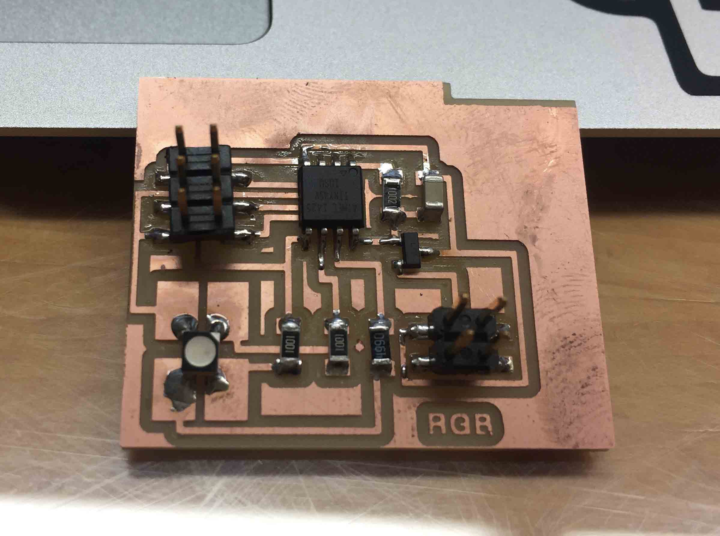
I have design another board for the output device. My final project board is designed to use a coin vibration motor. As Silvia suggest me, I have read this tutorial to understand which components are useful to use it. To create my board I need:
- Diodo SCH
- 0.1µF ceramic capacitor
- 1KΩ Resistor
- Transistor
Mosfet N is used expecially with ON and OFF devices, Mosfet P is a transistor with improved skills. More electron pass in it. ( link) On Eagle I have drew my board and then I have milled and soldered it.
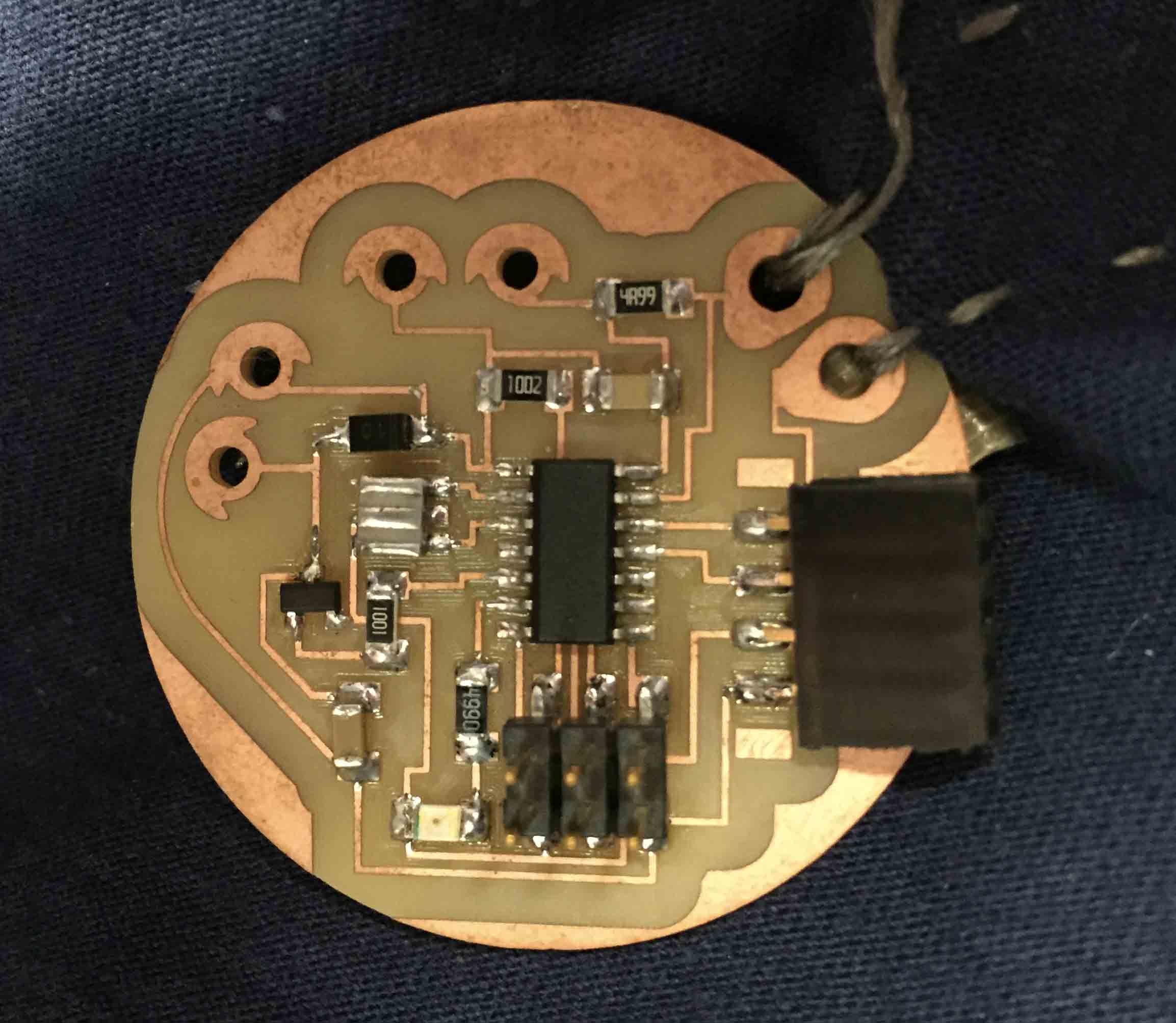
As you can see, in it I have included a Led as debug. I think it is useful to had an quick test. To use my board with coin vibration motor I have wrote this sketch in Arduino IDE:
int ledPin = 7; // choose the pin for the LED
int motPin = 8; //pin motore
int vePin = A0;   // choose the input pin (for a pushbutton)
int val = 0;     // variable for reading the pin status

void setup() {

  pinMode(motPin, OUTPUT);  // declare motor as output
  pinMode(ledPin, OUTPUT);  // declare LED as output
  pinMode(vePin, INPUT);    // declare pushbutton as input
}

void loop(){

  val = analogRead(vePin);  // read input value
  if (val > 60) {         // check if the input is HIGH (button released)
    digitalWrite(motPin, HIGH);  // turn motor OFF
    bluetooth.write(1);  //Il dato viene inviato al bluetooth perchè sia elaborato e quindi trasmesso
  } else {
    digitalWrite(motPin, LOW);  // turn motor ON

  }
}
If you read I have used an input device to test it. I have used the pressure sensor made for my final project.
DOWNLOAD
I spent most of my time to study how stepper motors works and I can says that they aren't a mistery for me now. I was scared about it at the beginning but now I'm very happy of my result.
You can download my files here

This work is licensed under aCreative Commons Attribution - ShareAlike 4.0 International License.