Design and build a wired &/or wireless network connecting at least two processors
Learning outcomes:
*Demonstrate workflows used in network design and construction.
*Implement and interpret networking protocols
Have you:
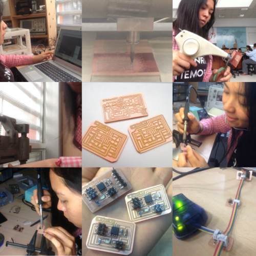
*Described your design and fabrication process using words/images/screenshots.
*Explained the programming process/es you used.
*Outlined problems and how you fixed them.
*Included original design files and code.
I have to design and build a wired or wireless network connecting at least two processors.
First step
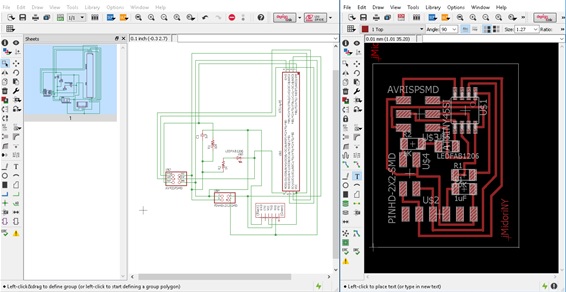
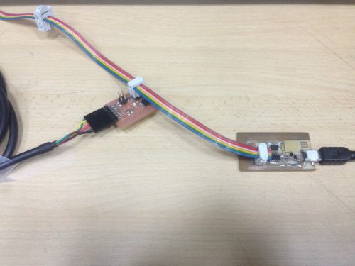
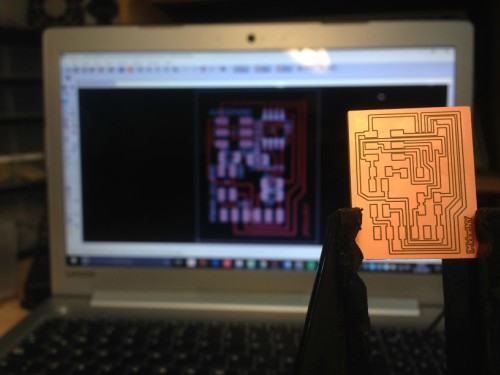
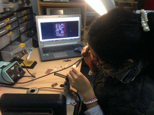
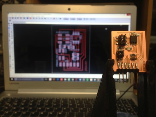
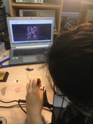
I chose to work with the RS232 as a serial bus asynchronous. Then I started designing the bridge and node boards with the "Eagle" software, then I performed all the procedure for its construction, first milling the card using the Roland Modela 20X machine and then soldered the components that are needed for each one. I used one bridge and two slave boards.
Here you have the list for bridge board:
JP1
Attiny45
R1-rst
C1
Pin HD 2*2 SMD
R2
Led
Here you have the list for slave boards:
JP1
Attiny45
R1-rst
C1
FTDI
Pin HD 2*2 SMD
R2
Led
Second step
To program the board, I downloaded from the Fab Academy classes, "C" and their respective "makefiles".
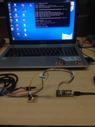
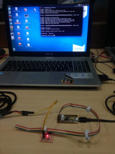
Using Ubuntu, I proceeded to program the micro controller with the previously downloaded files. I used UsbTiny to program it.
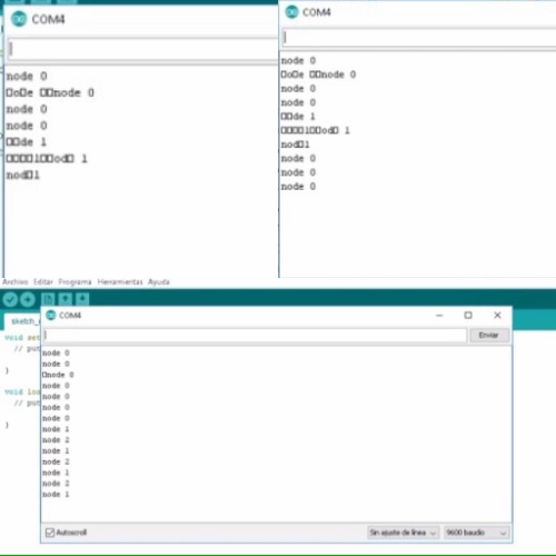
I defined each node in language .C, node 0 (bridge), node 1 y 2 (slaves).
The programming of each node was successful, however as we can see in the image and video when the computer sends the information, the nodes do not emitted any response.
In this case, I I used RS-232 as serial bus. In order to learn more, I read this data.
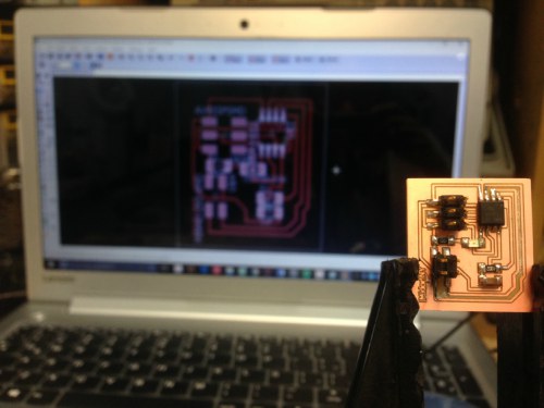
Fabricating boards:
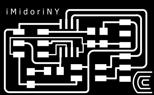
BRIDGE:
I opened Eagle software and after selected all the components that I needed from the fab library :
Here you have the list:
JP1
Attiny45
R1-rst
C1
Pin HD 2*2 SMD
R2
Led
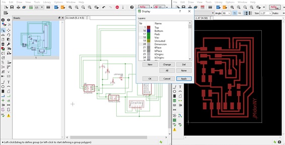
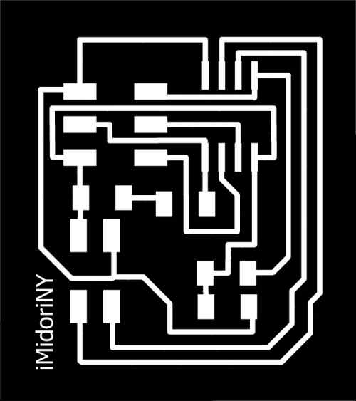
I ordered them and made a board file.
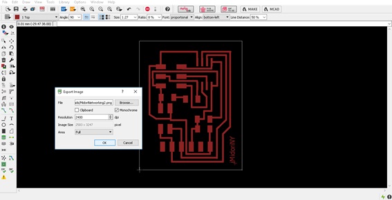
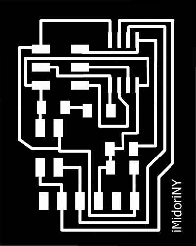
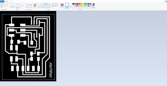
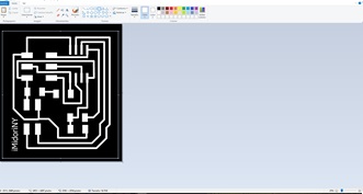
Then exported in .png format
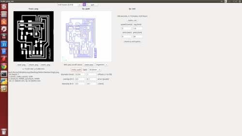
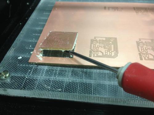
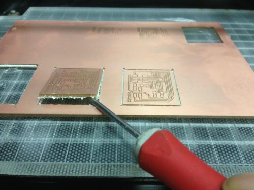
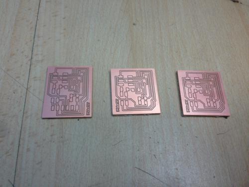
And start milling:
I used 0.010" milling tool to mill and 1/32" milling tool to cut,
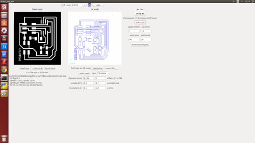
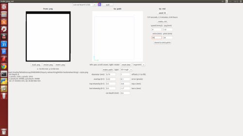
Upload the parameters with the following:
First using the 0.010" milling tool, I change it on the top. Load .png,
Parameters:
diameter (mm): 0.254
overlap: 0.5
offsets (-1 to fill): -1
error: 0.1 pixels
intensity: 0.5
z: -0.1 mm
And make .path
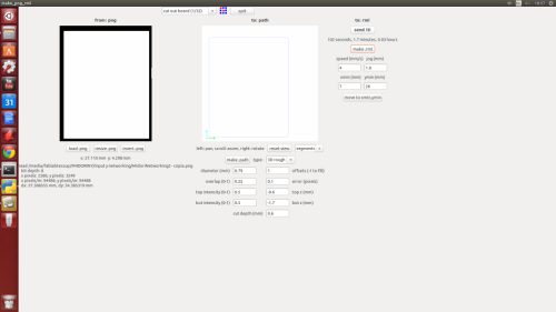
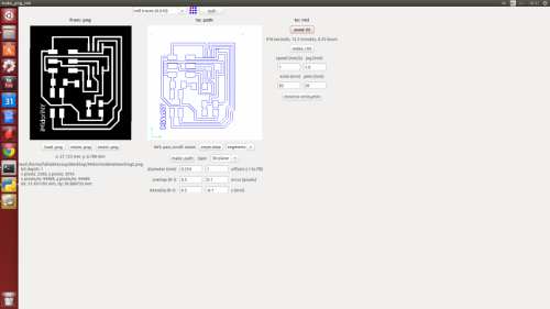
Set zero, moving "x", "y" and "z", click on make .rml and Send it !
Then, change the 0.010" milling tool for 1/32" milling tool to cut,
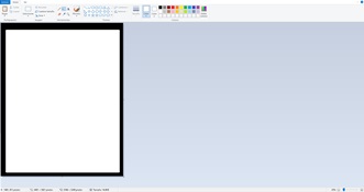
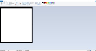
Additionally you create a silhouette of the board, you can do it with the same Eagle or with paint, I did it with paint and loaded the image with the same dimensions and set it at the same point of origin.
In this way, I got the "bridge" of my networking.
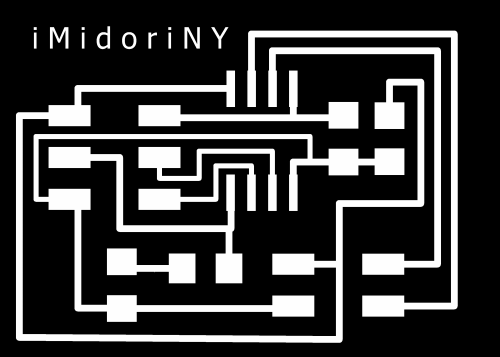
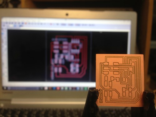
SLAVES:
Here you have the list of components for node boards:
JP1
Attiny45
R1-rst
C1
FTDI
Pin HD 2*2 SMD
R2
Led
In this case, we will just change the origin point at the software, to continue milling.
I exported in .png format
First using the 0.010" milling tool, I change it on the top. Load .png,
Parameters:
diameter (mm): 0.254
overlap: 0.5
offsets (-1 to fill): -1
error: 0.1 pixels
intensity: 0.5
z: -0.1 mm
And make .path
Set zero, moving "x", "y" and "z", click on make .rml and Send it !
Then, change the 0.010" milling tool for 1/32" milling tool to cut,
Additionally you create a silhouette of the board, you can do it with the same Eagle or with paint, I did it with paint and loaded the image with the same dimensions and set it at the same point of origin.
I cleaned the work area with a vacuum cleaner. And removed the boards.
After all, open arduino serial window, write numbers and see how leds blink.
Explaining with my own words Neil's code:
What I learned using this code is that is necessary to use a three state logic.
What it means three-state logic?
In digital electronics three-state, tri-state, or 3-state logic allows an output port to assume a high impedance state in addition to the 0 and 1 logic levels, effectively removing the output from the circuit.
This allows multiple circuits to share the same output line or lines (such as a bus which cannot listen to more than one device at a time).
The basic concept of the third state, high impedance (Hi-Z), is to effectively remove the device's influence from the rest of the circuit. If more than one device is electrically connected to another device, putting an output into the Hi-Z state is often used to prevent short circuits, or one device driving high (logical 1) against another device driving low (logical 0).
Three-state buffers can also be used to implement efficient multiplexers, especially those with large numbers of inputs.
Three-state buffers are essential to the operation of a shared electronic bus.
Three-state logic can reduce the number of wires needed to drive a set of LEDs (tri-state multiplexing or Charlieplexing).
What I did when I realize that my networking is not working complet?
Thinking that the problem is about soldering I checked each board with the multimeter.
It is not the problem.
With the help of my instructor I learned that the problem is the communication speed. Then I have to change the value of "bit_delay_time".
If you have this problem in the future, I recommend to you to do it. Actually I am out of home I can not complete this part. I am in Paris, France and my boards are in Huancayo, Peru.
Follow me on my social networks, I will do it when I arrive at home.
Conclusion:
Through this experience and talking with the instructor, I learned that the problem that is presented does not have anything to do with the soldering of the components, but this happens because it depends on the speed. The times in this type of boards depend on an internal oscillator. You should play with the times in the program to make sure it is correct. This happens when it is not integrated into a Hardware, for it is an RX TX software. I have to check the speed and parameters.
Self Evaluation:
I achieved this challenge working with the RS232 as serial bus.
Through this assignment I will use a bluetooth for my final project, creating a networking connecting to my mimiduino.