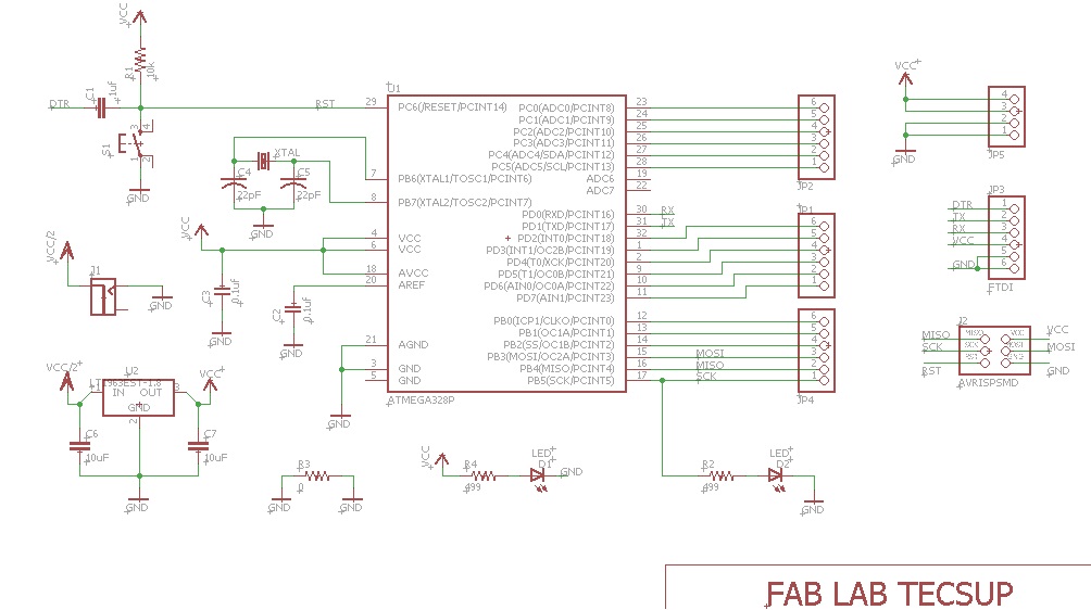
The activity of this week was to make a circuit wired network of two processors. In my case perform I2C communication. Use the Atmega 328P for activity development..
To do this the following steps are followed:
STEP 1: DOWNLOAD FILES
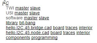
Files and communications networks may be found in the following page:
I decided to work with serial bus --> I2C. I developed the fabduino card, to develop I2C communication.
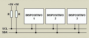
The I2C bus, a standard that facilitates communication between microcontrollers, memories and other devices with a certain level of "intelligence", requires only two lines of signal and a common or mass. It was designed for this purpose by Philips and allows the exchange of information between many devices at an acceptable speed, about 100 Kbits per second, although there are special cases in which the clock reaches up to 3.4 MHz.
The data communication methodology of the I2C bus is serial and synchronous. One of the bus signals dials time (clock pulses) and the other is used to exchange data.
THE SIGNS:
SCL (System Clock) is the line of the clock pulses that synchronize the system.
SDA (System Data) is the line through which data moves between devices.
Common GND of the interconnection between all the devices "hooked" to the bus.
STEP 2: CONSTRUCTION OF FABDUINO
Two fabduino were made for I2C communication.
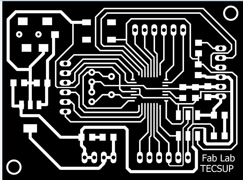
To card "NODE" the " traces" and "inside" files are used. It must be made two of these cards.
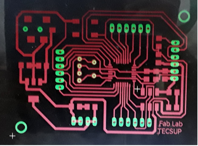
STEP 3: WELD COMPONENTS IN CARD
To weld the components of the card is necessary to use the file " components". It can be seen the position of the various components on the card.
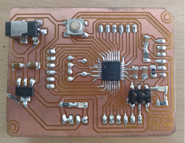
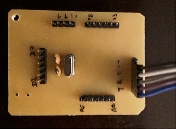
In the next picture the end result of the card with the components and soldiers shown.
BRIDGE
STEP 4: LOAD THE PROGRAM CARDS
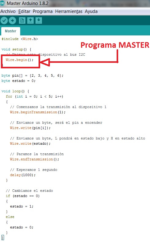
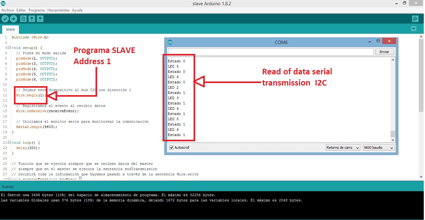
Programming was developed for the Master and the slave respectively. The WIRE library was used for the I2C communication, the slave is configured with an address 1 as shown in the figure.
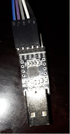
In the figure of the slave fabduino it is observed through the "Arduino serial monitor" the sending of orders from the Fabduino Maestro (the current state of the outputs in the slave). The USB-SERIAL DTR-RXD-TXD-5V-GND cable was used to transmit the programming to the Master and Slave Fabduins.
STEP 5: CHECKING THE OPERATION OF THE APPLICATION
For this part we used the " Arduino Serial Monitor", for it was held the following:
• Open the Arduino IDE application.
• Open the "Serial Monitor" from the "Tools - Serial Monitor" menu.
• Set the communication speed to 9600 baud.
• The status of the ports is observed 2-3-4-5 of Fabduino SLAVE.
To see the operation shown in this video.