Exercise 15 Networking and Communications
Exercise Requirements
To build a wired &/or wireless network connecting at least two processors.
Introduction
We have been making PCB boards with individual micro-controller to do something on its own so far (whether input or output or using it as an ISP). This week, we learn how to build a network using two or more micro-controller boards and to have them talk to one another. In simple term we learnt how to communicate with more than one micro-controllers.
Some of the different methods of networking and communication discussed in class are listed as follow:
- Synchronous serial communication
- Asynchronous serial communication
- I2C
- Serial Peripheral Interface (SPI)
I would probably explore the I2C communication and follow by Asynchronous Serial communication (which are between one master ATtiny 45 controller board and two slave ATtiny 45 boards).
I2C Communication Network
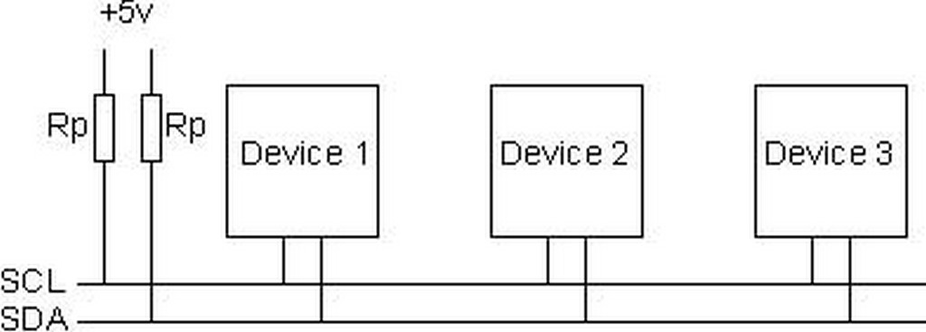
The I2C bus is a half-duplex, synchronous, multi-master bus requiring only two signal wires: data (SDA) and clock (SCL). These lines are pulled high via pull-up resistors and controlled by the hardware via open-drain drivers, giving a wired-AND interface. I2C uses an addressable communications protocol that allows the master to communicate with individual slaves using a 7-bit or 10-bit address. During communication with slave devices, the master generates all clock signals for both communication to and from the slave.
Each communication begins with the master generating a start condition, an 8-bit data word, an acknowledge bit, followed by a stop condition or a repeated start. Each data bit transition takes place while SCL is low, except for the start and stop conditions.
The start condition is a high-to-low transition of the SDA line while the SCL line is high. A stop condition is a low-to-high transition of the SDA line while the SCL line is high. The acknowledge bit is generated by the receiver of the message by pulling the SDA line low while the master releases the line and allows it to float high. If the master reads the acknowledge bit as high, it should consider the last communication word not received and take appropriate action, including possibly resending the data.
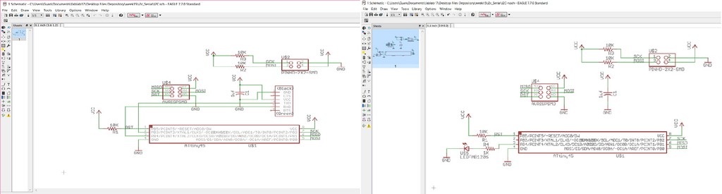
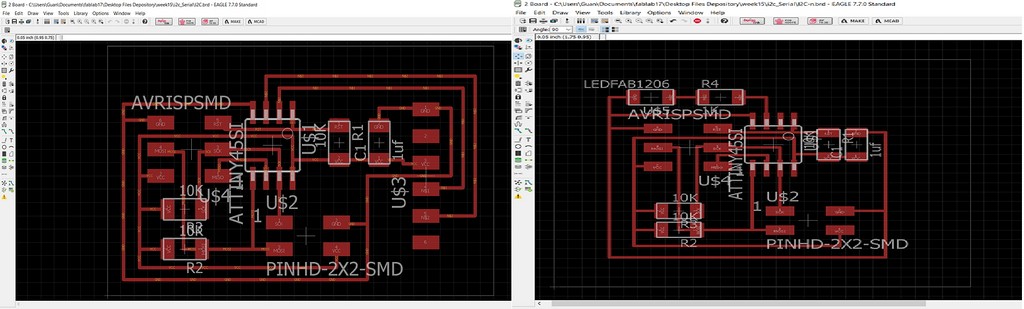
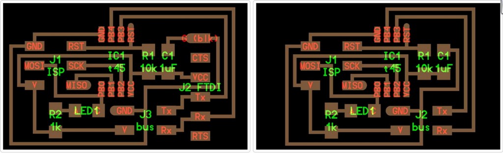
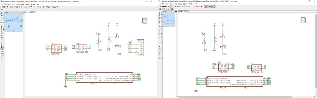
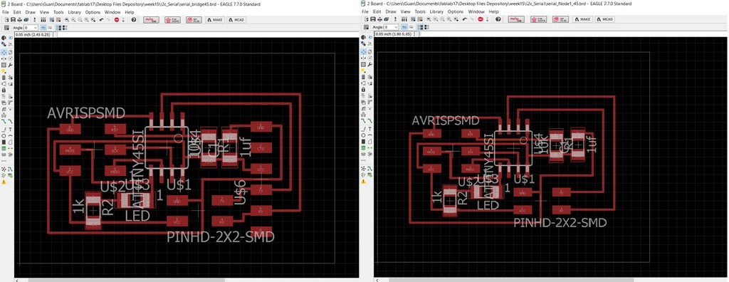
Designing the I2C communication boards
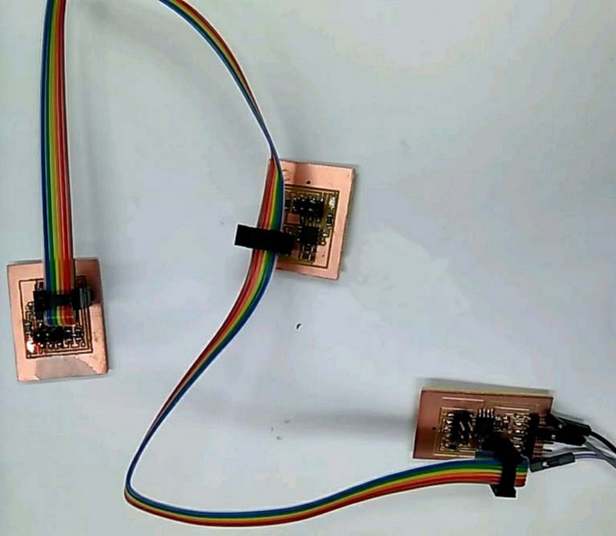
I would be referring to Neil's boards and using all ATtiny45 micro-controllers in my I2C communication boards design.
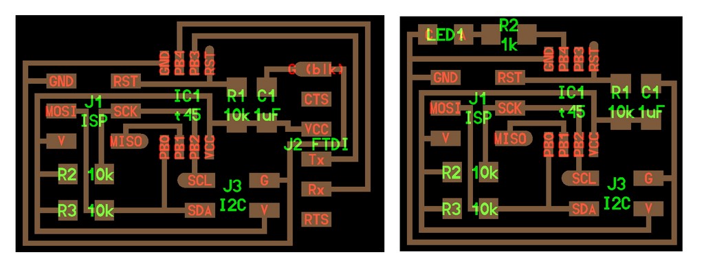
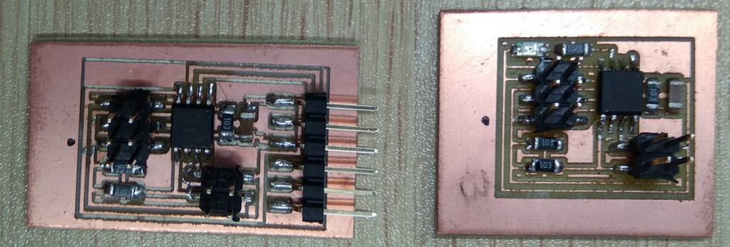
Components needed to stuff the bridge and node boards.
- 1 x BRIDGE:
- 1 x ATTINY45
- 1 x 3X2 PIN HEADER (ARVISP SMD)
- 1 x 2X2 PIN HEADER SMD
- 1 x 1X6 FTDI SMD HEADER
- 1 x CAPACITOR 1 uf
- 3 x 10 k Ohm RESISTOR RES-US1206FAB
- 2 x NODES:
- 2 x ATTINY45
- 2 x 3X2 PIN HEADER (ARVISP SMD)
- 2 x 2X2 PIN HEADER SMD
- 2 x CAPACITOR 1 uf
- 2 x 10 k Ohm RESISTOR RES-US1206FAB
- 2 x LED 1206 smd
- 2 x 1 k Ohm RESISTOR RES-US1206FAB
Programming the I2C ATtiny45 micro-controller boards,
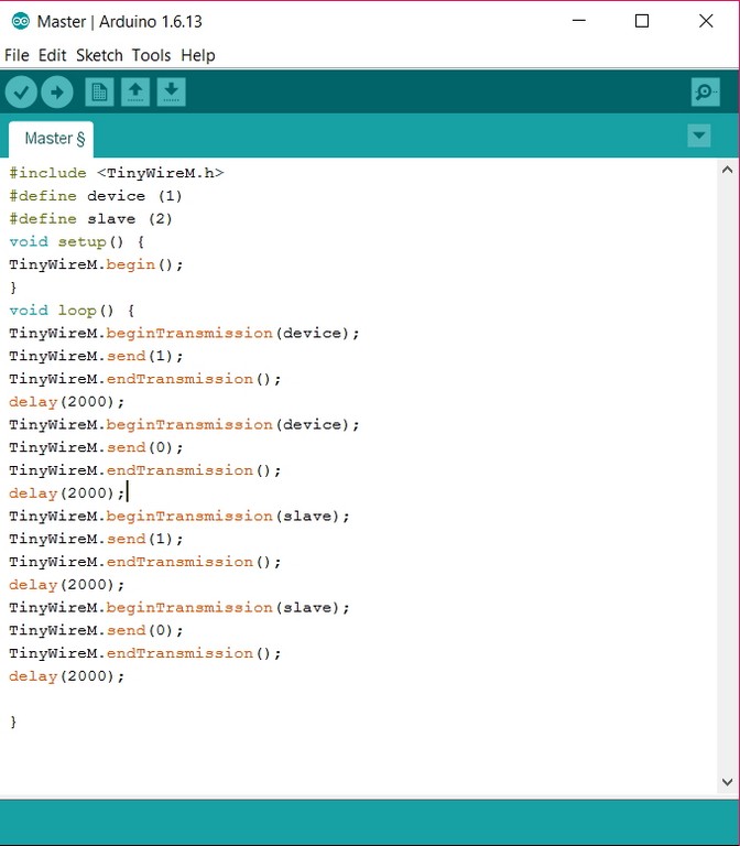
Programming of I2C Bridge as Master
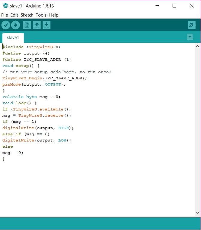
Programming of I2C Node as Slave1
Programming of I2C Node as Slave2
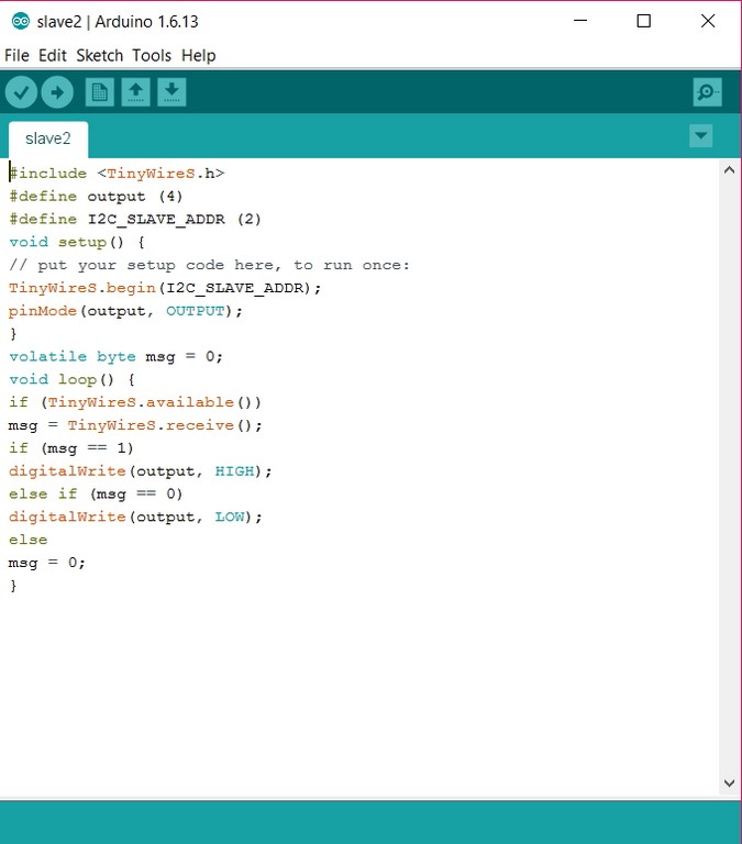
Output of I2C Communication Network as a video Clip.
The asynchronous serial communication boards
Programming of I2C Node as Slave2
Output of I2C Communication Network as a video Clip.
The asynchronous serial communication boards
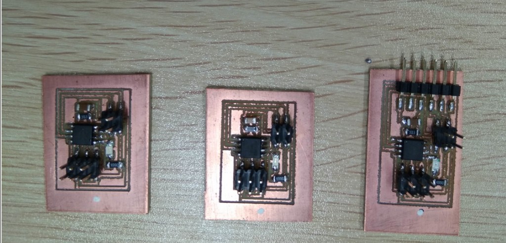
Similarly for this study, I would be referring to Prof. Neil's boards in making the bridge board and two node boards.
Components needed
- 1 x BRIDGE:
- 1 x ATTINY45
- 1 x 3X2 PIN HEADER (ARVISP SMD)
- 1 x 2X2 PIN HEADER SMD
- 1 x 1X6 FTDI SMD HEADER
- 1 x CAPACITOR 1 uf
- 1 x 10 k Ohm RESISTOR RES-US1206FAB
- 1 x LED 1206 smd
- 1 x 1 k Ohm RESISTOR RES-US1206FAB
- 1 x OMRON SWITCH
- 2 x NODES:
- 2 x ATTINY45
- 2 x 3X2 PIN HEADER (ARVISP SMD)
- 2 x 2X2 PIN HEADER SMD
- 2 x CAPACITOR 1 uf
- 2 x 10 k Ohm RESISTOR RES-US1206FAB
- 2 x LED 1206 smd
- 2 x 1 k Ohm RESISTOR RES-US1206FAB
Programming the Asynchronous ATtiny45 micro-controller boards,
Programming of Asynchronous Bridge as Master
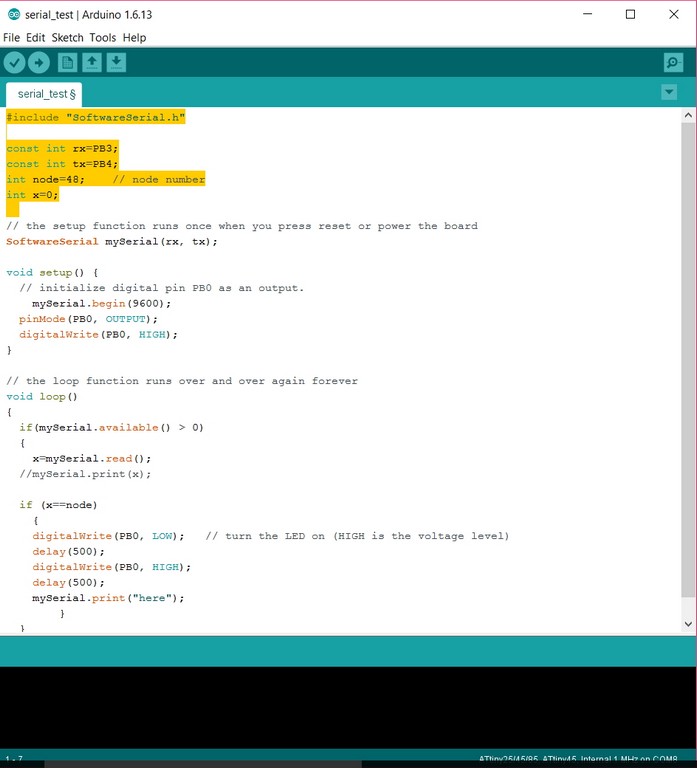
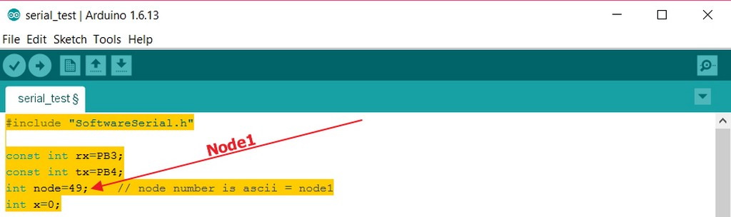
Programming of Asynchronous Node

At first we attempted to flash the bridge and nodes using Prof. Neil's code available in the class webpage for this week on Asynchronous Network Communication. The results were irregular. No matter what key/ character had been "pressed", three LED all blinked. But serial monitor shown no feedback data at all. So we decided to proceed to rewrite the code in Arduino to see how was the responses.
As such we turn to use Aduino IDE and wrote a similar code to emulate the '0'pressed equal to node0 and '1' pressed equal to node1 and '2' represent node2. I would like to say that we have succeeded in producing the code in IDE that could replicate what was being shown in the class video, but in actual fact we are not. When the numbers (0,1, and 2) being pressed, the LEDs on each node take turn to lit up. But there was no display at neither the serial monitor or the term.py. Till the moment when writing this report, I can only satisfied with the result of individual LED was able to lit up in response to the nodes and master board number. A video clip of the results is as shown.
Output of Asynchronous Serial Communication Network as a video Clip1 an video clip2.
After completed the Arduino testing, we were almost ran out of clue and idea what other thing that could have gone wrong, so we decided to try out Neil's c code one more time before going to seek for advise from our local instructor. Guess what, the code suddenly work with slight flaws on node2 where the returns are garbage. Our findings are as captured in video clip2 as follow:
Reflections
Electronic weeks were the most hectic for me, it is no different for this week exercise. I was hopeful that, I can learnt something which can be directly applicable in my Final project. But rather, ending up struggle with Asychronous communication network troubleshooting.
Download work files
References
- Asynchronous serial communication
- How I2C Communication Works and How To Use It with Arduino
- Serial Protocols Compared
- Serial Communication
- Serial Peripheral Interface (SPI)
- I2C
- 11B. Serial Communications: I2C and SPI