Exercise 13 Input Devices
Assignment Requirement
Our assignment for this week is to build a microcontroller board with some input device(s) and program it:
- add a sensor to a microcontroller board that we have designed and read it (sensor)
- measure something and read it on a computer
ATtiny 45 for the study of Input Devices and the Study of Datasheet
First up Prof Neil started this week's lesson by emphazing the iportant to refer to the datasheet of ATtiny45. To begin with he touched base on section 10.) I/O Ports, section 16.) Analog Comparator, and section 17.) Analog to Digital Converter; of ATtiny45 datasheet which could be located ATtiny45 DataSheet.
The ATtiny45 is a low-power CMOS 8-bit microcontroller that has an internal oscillator of 8MHz. The high-performance, low-power Atmel 8-bit AVR RISC-based microcontroller combines 4KB ISP flash memory, 256-Byte EEPROM, 256B SRAM, 6 general purpose I/O lines, 32 general purpose working registers, one 8-bit timer/counter with compare modes, one 8-bit high speed timer/counter, USI, internal and external Interrupts, 4-channel 10-bit A/D converter, programmable watchdog timer with internal oscillator, three software selectable power saving modes, and debugWIRE for on-chip debugging. The device achieves a throughput of 20 MIPS at 20 MHz and operates between 2.7-5.5 volts. Idle mode stops the CPU while allowing the SRAM, Timer/Counter, ADC, Analog Comparator, and Interrupt system to continue functioning. Power-down mode saves the register contents, disabling all chip functions until the next Interrupt or Hardware Reset. ADC Noise Reduction mode stops the CPU and all I/O modules except ADC, to minimize switching noise during ADC conversions.
Section 10: I/O Ports.
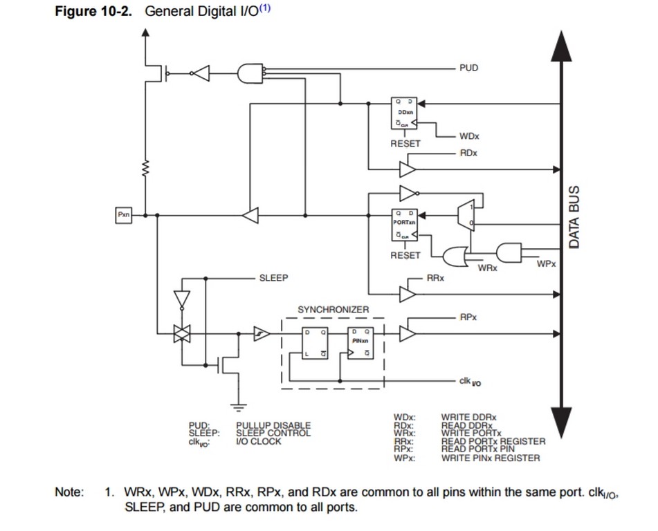
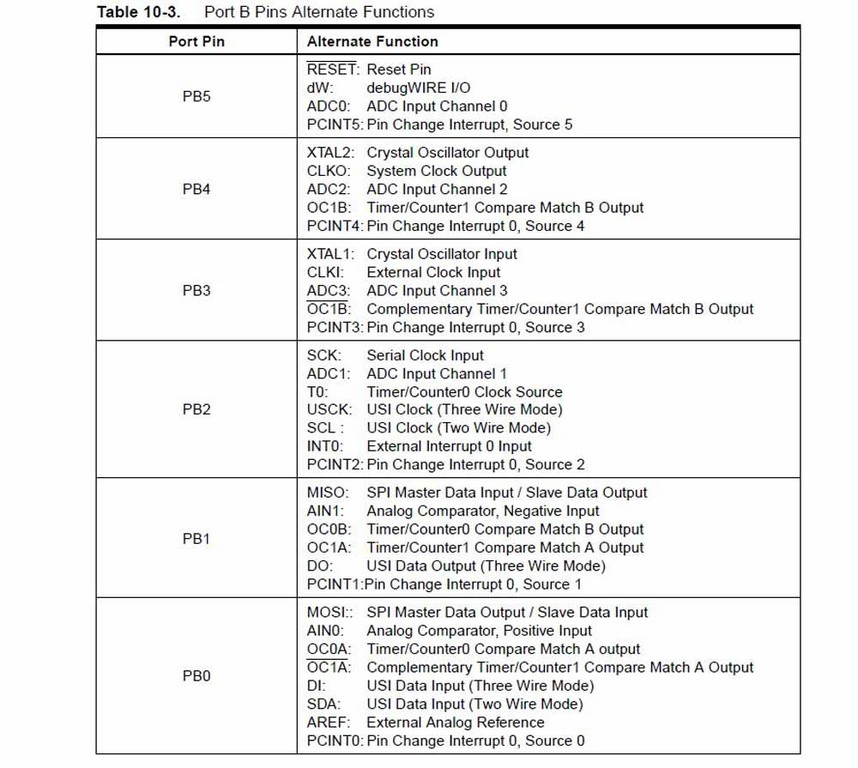
For details refer to the descriptions of the alternative function of each I/O port in the datasheet.
Section 16: Analog Comparator
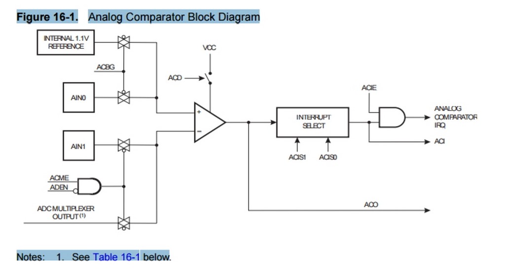
For details refer to the descriptions of the Analog Comparator Function in the datasheet.
Section 17: Analog to Digital Converter
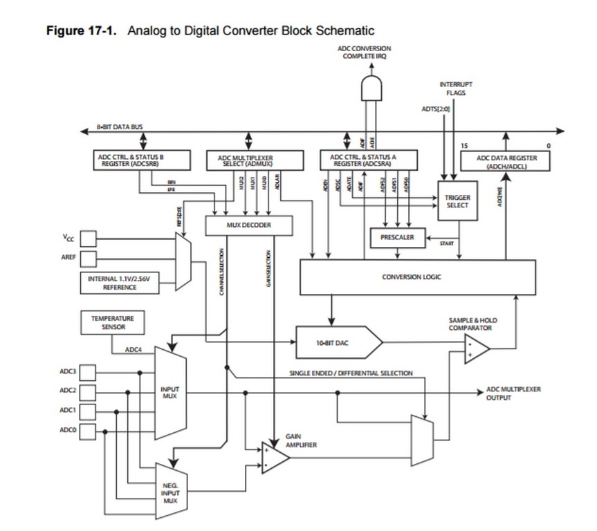
For details refer to the descriptions of the Analog to Digital Converter Function in the datasheet.
In the lecture, Prof Neil also mentioned about the focus on the input devices that we are going to use in our Final Project and using the weekly assignment exercise practise to work toward the final project. That was what I intended to do at the begining. My choices of two input devices that I would most probably be using are Phototransistor and Thermistor and the study and exercises are documented as follow:
Phototransistor
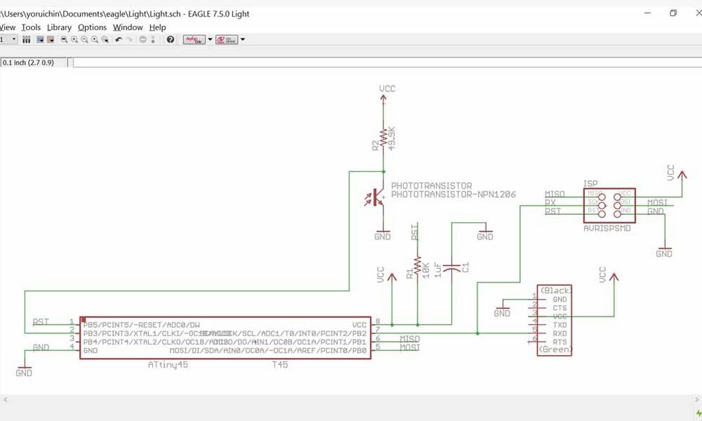
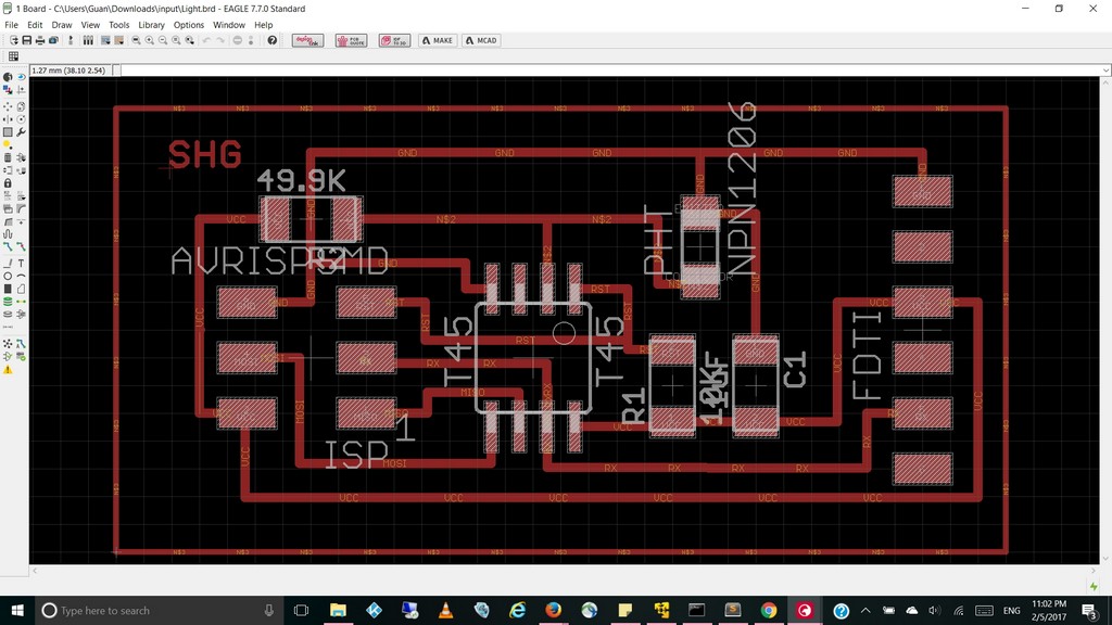
I have taken reference from the board in this week's lecture and previous year senior's exercise on input devices to reroute and built my phototransistor cuircuit board. After created the board file in Eagle CAD, I then proceed to generate the etch.tap milling file to be used in our PCB2020B CNC Router. Following that, I transfered the file and using a thumbdirve and milled out my own phototransistor board using our PCB2020B CNC router with the steps that I have been practising since PCB2020B CNC Router usage steps
After milled out my phototransistor board, I proceed to stuff the board with the following components.
Components List for my Phototransistor Board.
- 1 x ATTINY45
- 1 x 3X2 PIN HEADER (ARVISP SMD)
- 1 X 1X6 FTDI SMD HEADER
- 1 x CAPACITOR 1 uf
- 1 x Phototransistor
- 1 X 10 k ohm RESISTOR RES-US1206FAB
- 1 X 49.9 k ohm RESISTOR RES-US1206FAB
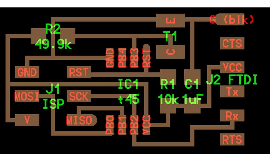
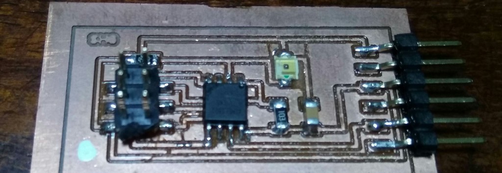
Things to note: the ATtiny chip and phototransistor have polarity. Polarity on the ATtiny chip is denoted by a faint dot on pin 1 and polarity on the phototransistor is denoted by a green marker that should face the "C" which stands for Collector. The other side, "E" stands for emitter. Another valuable lesson learnt - the photo transistor plastic cap can't take the high heat of the rework station.
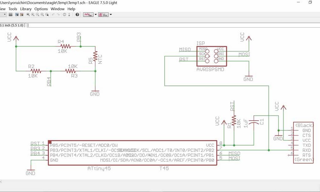
Thermistor
Another Input device that I would be included is in the measuring of temperature using a NTC thermistor. We use a NTC thermistor for this assignment. Many NTC thermistors are made from a pressed disc, rod, plate, bead or cast chip of semiconducting material such as sintered metal oxides. They work because raising the temperature of a semiconductor increases the number of active charge carriers - it promotes them into the conduction band. The more charge carriers that are available, the more current a material can conduct. To measure temperature, we need to measure the resistance. However, a microcontroller does not have a resistance-meter built in. Instead, because it has an analog-digital-converter (ADC), we can convert the resistance into a voltage, and we do that by adding another resistor and connecting them in series. Now we just measure the voltage in the middle, as the resistance changes, the voltage changes too.
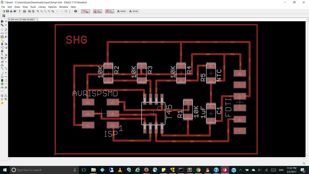
Similary, I went through the exact PCB milling steps using our PCB2020B CNC Router to produce my Temperature sensing input board using a NTC thermistor. With this board I later on further explore in my final project to make the board doing something with my choice of output device.
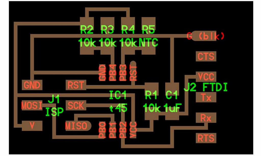
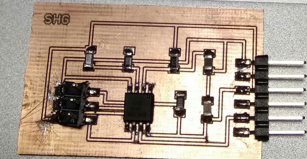
Components needed
- 1 x ATTINY45
- 1 x 3X2 PIN HEADER (ARVISP SMD)
- 1 X 1X6 FTDI SMD HEADER
- 1 x CAPACITOR 1 uf
- 1 x THERMISTOR NTC 10K OHM 1206
- 4 X 10 k ohm RESISTOR RES-US1206FAB
- 1 X 49.9 k ohm RESISTOR RES-US1206FAB
Using the sensors boards to take measurement and display in Computer.
What being describe by Prof Neil during the lecture on the programming of these input devices in c code, and using python to display the interaction result through FTDI serial communication might be too rush and too short a time to achieve. Then I recalled what we did in Exercise week 8 that I could test the sensors and receive a response via the FTDI USB to TTL Serial Converter to be displayed on the Putty terminal. So I told myself to finish this first and if time permitted; I would revisit what were been thought in this week's lecture.
Study of Phototransistor
Taking reference from our senior on the study of phototransistor on previous year, I modified the code using as follow and uploaded through my FabISB board using Arduino IDE.
   #include <SoftwareSerial.h>

    SoftwareSerial mySerial = SoftwareSerial (0,2);

    int sensorPin = A3;

    int sensorValue = 0;

   void setup() {
     mySerial.begin(9600);
    }

   void loop() {
   sensorValue = analogRead(sensorPin);
    mySerial.print(sensorValue);
    if (sensorValue < 300)
    mySerial.println(" Bright Light Present!.");
  else
    mySerial.println(" Too Dark, ON light Please!.");
    delay(1000);
   }

}
Study of Thermistor
From the initial study of our senior arduino programme, I found that the resistance value of thermistor decreases with heat, and increases when temperature reduce. I also noted that at aircon room temperature, resistance is between 500-530. Human direct touch on thermistor temperature will bring the value down to about 490-500. These findings sort of formed the basis of my temperature study and programming in ardunino and further modification to read the temperature of air flow generated by my laptop.
  #include <SoftwareSerial.h>
   SoftwareSerial mySerial = SoftwareSerial (0,2);
   int sensorPin = A3;
   int sensorValue = 0;
  #include <math.h>
   double Thermistor(int RawADC) {
   double Temp;
   // Temp = log(10000.0*((1024.0/RawADC-1)));
      Temp      =log(10000.0/(1024.0/RawADC-1)); // for pull-up configuration
      Temp = 1 / (0.001129148 + (0.000234125 + (0.0000000876741 * Temp * Temp ))* Temp );
     Temp = Temp - 273.15;            // Convert Kelvin to Celcius
   //Temp = (Temp * 9.0)/ 5.0 + 32.0; // Convert Celcius to Fahrenheit
     return Temp;
    }

   void setup() {
   mySerial.begin(9600);
   pinMode(PB1, OUTPUT);
   pinMode(PB0, OUTPUT);
    }

   void loop() {
    int Temperature= (Thermistor(analogRead(PB3)));
    mySerial.println("Current Temp in C:");
    mySerial.println(Temperature);  // display Celcius

    delay(500);
     if (Temperature >=40)
     {
        digitalWrite(PB0, HIGH);

     }
    else if (Temperature >=35 && Temperature <40)
     {

      digitalWrite(PB0, HIGH);

      delay(100);
        digitalWrite(PB0, LOW);
      }
    else{
      digitalWrite(PB0, LOW);
     }
  }
Flashing of Programme with Atmel Studio 7
After completed my basic studies on phototransistor and thermistor sensors, I decided to eplore how to use the c code and python code mentioned in this week lesson. Basically I did not make any additional changes to the c program and the python code since my board is exactly like the one on the class page.
Temperature sensing with thermistor using c code and python to display through serial port.
To start with, I downloaded the hello.temp.45.c from class page to take reading of the room temperature.
Flashing my thermistor sensor board:
  avrdude.exe: Version 5.10, compiled on Jan 19 2010 at 10:45:23
             Copyright (c) 2000-2005 Brian Dean, http://www.bdmicro.com/
             Copyright (c) 2007-2009 Joerg Wunsch

             System wide configuration file is "C:\WinAVR-20100110\bin\avrdude.conf"

             Using Port                    : lpt1
             Using Programmer              : usbtiny
             AVR Part                      : ATtiny45
             Chip Erase delay              : 4500 us
             PAGEL                         : P00
             BS2                           : P00
             RESET disposition             : possible i/o
             RETRY pulse                   : SCK
             serial program mode           : yes
             parallel program mode         : yes
             Timeout                       : 200
             StabDelay                     : 100
             CmdexeDelay                   : 25
             SyncLoops                     : 32
             ByteDelay                     : 0
             PollIndex                     : 3
             PollValue                     : 0x53
             Memory Detail                 :

                                      Block Poll               Page                       Polled
               Memory Type Mode Delay Size  Indx Paged  Size   Size #Pages MinW  MaxW   ReadBack
               ----------- ---- ----- ----- ---- ------ ------ ---- ------ ----- ----- ---------
               eeprom        65     6     4    0 no        256    4      0  4000  4500 0xff 0xff
                                      Block Poll               Page                       Polled
               Memory Type Mode Delay Size  Indx Paged  Size   Size #Pages MinW  MaxW   ReadBack
               ----------- ---- ----- ----- ---- ------ ------ ---- ------ ----- ----- ---------
               flash         65     6    32    0 yes      4096   64     64  4500  4500 0xff 0xff
                                      Block Poll               Page                       Polled
               Memory Type Mode Delay Size  Indx Paged  Size   Size #Pages MinW  MaxW   ReadBack
               ----------- ---- ----- ----- ---- ------ ------ ---- ------ ----- ----- ---------
               signature      0     0     0    0 no          3    0      0     0     0 0x00 0x00
                                      Block Poll               Page                       Polled
               Memory Type Mode Delay Size  Indx Paged  Size   Size #Pages MinW  MaxW   ReadBack
               ----------- ---- ----- ----- ---- ------ ------ ---- ------ ----- ----- ---------
               lock           0     0     0    0 no          1    0      0  9000  9000 0x00 0x00
                                      Block Poll               Page                       Polled
               Memory Type Mode Delay Size  Indx Paged  Size   Size #Pages MinW  MaxW   ReadBack
               ----------- ---- ----- ----- ---- ------ ------ ---- ------ ----- ----- ---------
               lfuse          0     0     0    0 no          1    0      0  9000  9000 0x00 0x00
                                      Block Poll               Page                       Polled
               Memory Type Mode Delay Size  Indx Paged  Size   Size #Pages MinW  MaxW   ReadBack
               ----------- ---- ----- ----- ---- ------ ------ ---- ------ ----- ----- ---------
               hfuse          0     0     0    0 no          1    0      0  9000  9000 0x00 0x00
                                      Block Poll               Page                       Polled
               Memory Type Mode Delay Size  Indx Paged  Size   Size #Pages MinW  MaxW   ReadBack
               ----------- ---- ----- ----- ---- ------ ------ ---- ------ ----- ----- ---------
               efuse          0     0     0    0 no          1    0      0  9000  9000 0x00 0x00
                                      Block Poll               Page                       Polled
               Memory Type Mode Delay Size  Indx Paged  Size   Size #Pages MinW  MaxW   ReadBack
               ----------- ---- ----- ----- ---- ------ ------ ---- ------ ----- ----- ---------
               calibration    0     0     0    0 no          2    0      0     0     0 0x00 0x00

             Programmer Type : USBtiny
             Description     : USBtiny simple USB programmer, http://www.ladyada.net/make/usbtinyisp/
avrdude.exe: programmer operation not supported

avrdude.exe: Using SCK period of 10 usec
CMD: [ac 53 00 00] [00 00 53 00]
avrdude.exe: AVR device initialized and ready to accept instructions

Reading | CMD: [30 00 00 00] [00 30 00 1e]
CMD: [30 00 01 00] [00 30 00 92]
################CMD: [30 00 02 00] [00 30 00 06]
################################## | 100% 0.00s

avrdude.exe: Device signature = 0x1e9206
CMD: [50 00 00 00] [00 50 00 e2]
avrdude.exe: safemode read 1, lfuse value: e2
CMD: [50 00 00 00] [00 50 00 e2]
avrdude.exe: safemode read 2, lfuse value: e2
CMD: [50 00 00 00] [00 50 00 e2]
avrdude.exe: safemode read 3, lfuse value: e2
avrdude.exe: safemode: lfuse reads as E2
CMD: [58 08 00 00] [00 58 08 df]
avrdude.exe: safemode read 1, hfuse value: df
CMD: [58 08 00 00] [00 58 08 df]
avrdude.exe: safemode read 2, hfuse value: df
CMD: [58 08 00 00] [00 58 08 df]
avrdude.exe: safemode read 3, hfuse value: df
avrdude.exe: safemode: hfuse reads as DF
CMD: [50 08 00 00] [00 50 08 ff]
avrdude.exe: safemode read 1, efuse value: ff
CMD: [50 08 00 00] [00 50 08 ff]
avrdude.exe: safemode read 2, efuse value: ff
CMD: [50 08 00 00] [00 50 08 ff]
avrdude.exe: safemode read 3, efuse value: ff
avrdude.exe: safemode: efuse reads as FF
avrdude.exe: NOTE: FLASH memory has been specified, an erase cycle will be performed
             To disable this feature, specify the -D option.
CMD: [a0 00 fc 00] [00 a0 00 ff]
CMD: [a0 00 fd 00] [00 a0 00 ff]
CMD: [a0 00 fe 00] [00 a0 00 ff]
CMD: [a0 00 ff 00] [00 a0 00 ff]
avrdude.exe: erasing chip
CMD: [ac 80 00 00] [00 ac 80 00]
avrdude.exe: Using SCK period of 10 usec
CMD: [ac 53 00 00] [00 ac 53 00]
avrdude.exe: reading input file ".hex"
avrdude.exe: can't open input file .hex: No such file or directory
avrdude.exe: write to file '.hex' failed

CMD: [50 00 00 00] [00 50 00 e2]
avrdude.exe: safemode read 1, lfuse value: e2
CMD: [50 00 00 00] [00 50 00 e2]
avrdude.exe: safemode read 2, lfuse value: e2
CMD: [50 00 00 00] [00 50 00 e2]
avrdude.exe: safemode read 3, lfuse value: e2
avrdude.exe: safemode: lfuse reads as E2
CMD: [58 08 00 00] [00 58 08 df]
avrdude.exe: safemode read 1, hfuse value: df
CMD: [58 08 00 00] [00 58 08 df]
avrdude.exe: safemode read 2, hfuse value: df
CMD: [58 08 00 00] [00 58 08 df]
avrdude.exe: safemode read 3, hfuse value: df
avrdude.exe: safemode: hfuse reads as DF
CMD: [50 08 00 00] [00 50 08 ff]
avrdude.exe: safemode read 1, efuse value: ff
CMD: [50 08 00 00] [00 50 08 ff]
avrdude.exe: safemode read 2, efuse value: ff
CMD: [50 08 00 00] [00 50 08 ff]
avrdude.exe: safemode read 3, efuse value: ff
avrdude.exe: safemode: efuse reads as FF
avrdude.exe: safemode: Fuses OK

avrdude.exe done.  Thank you.
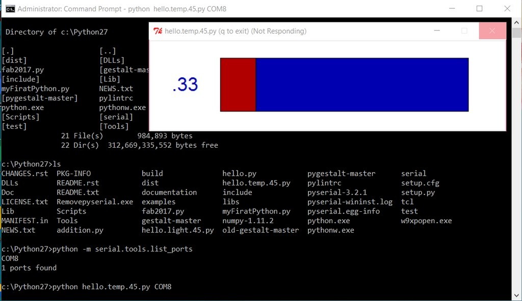
After going through all the hussle to installed numpy,tkinter and so on in python also Flash the C code using Atmel Studio 7, I then tried to run the Hello.temp.45.py file from command prompt as follow:
Download work files
References
Reflection
Once again, I finding myself running out of time for this week. Eventhough, I am trying to continue to troubleshoot on the thermistor sensor using python issue; but at some point of time, I still got to upload my assignment. I supposed for learning purposes, I would revisit this some point in the future.