Exercise 10 Output Devices
Assignment Requirement
- add an output device to a microcontroller board you've designed and program it to do something
Introduction
We kicked off the week with an introduction to the possible Output Devices to explore, with Prof. Neil Gershenfeld. After the lecture we use to have our usual next morning discussion of what to be done for tis week assignment with our local instructor, but because of work commitment, Singapore President Election Preparation matter, and personnal commitment we have rescheduled our meeting to Thursday afternoon. To begin, our local instructor Mr Steven Chew has suggested us to add a RGB LED to the microcontroller PCB we built on week 8. As my final project would possibily involve with LED lighting as one of the output and for the art of learning, I am most welcome with Steven suggestion.
RGB-LED Board
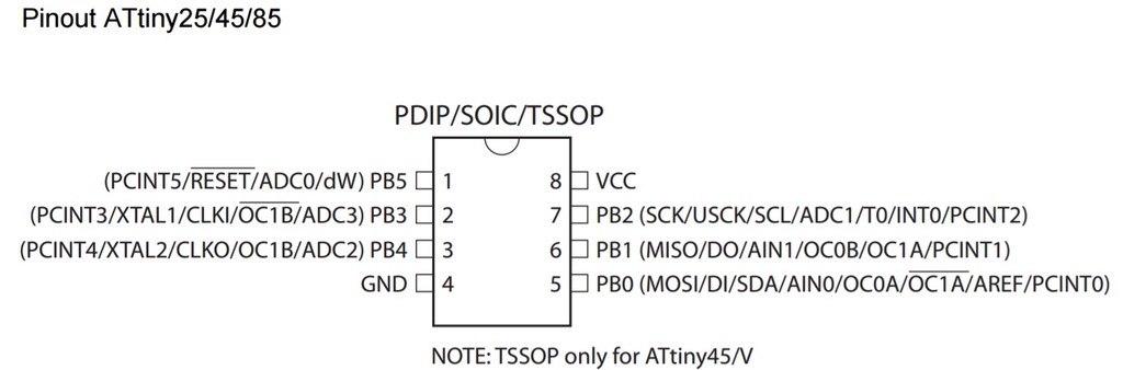
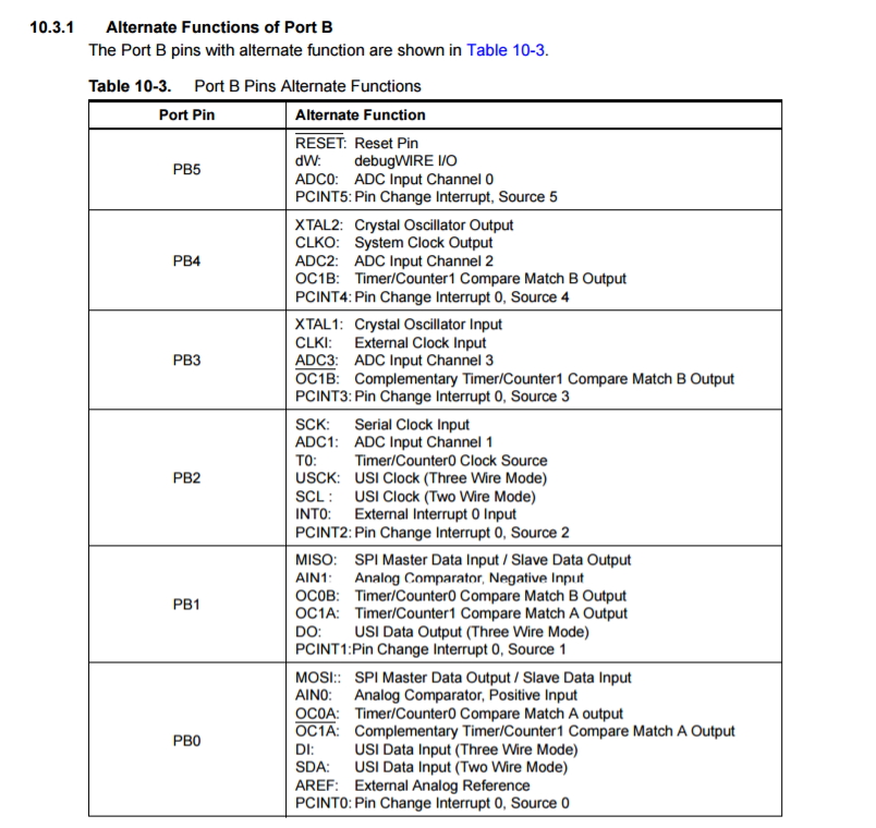
To begin my output device learning for this week, I've decided to simplify my ATtiny85 PCB built on week 8 using only a RGB led and no serial connector and no push button switch. I referred to exercise week 8 for the datasheet of ATtiny85/45 MCU that I used for this assignment. In particularly the pins configuration and portB alternative function table, I found the information useful to be included a follow:
With these useful inforamtion then I proceed to design my RGB LED ATtiny 85 board in Eagle CAD and the following are images of my schematics diagram and board files.
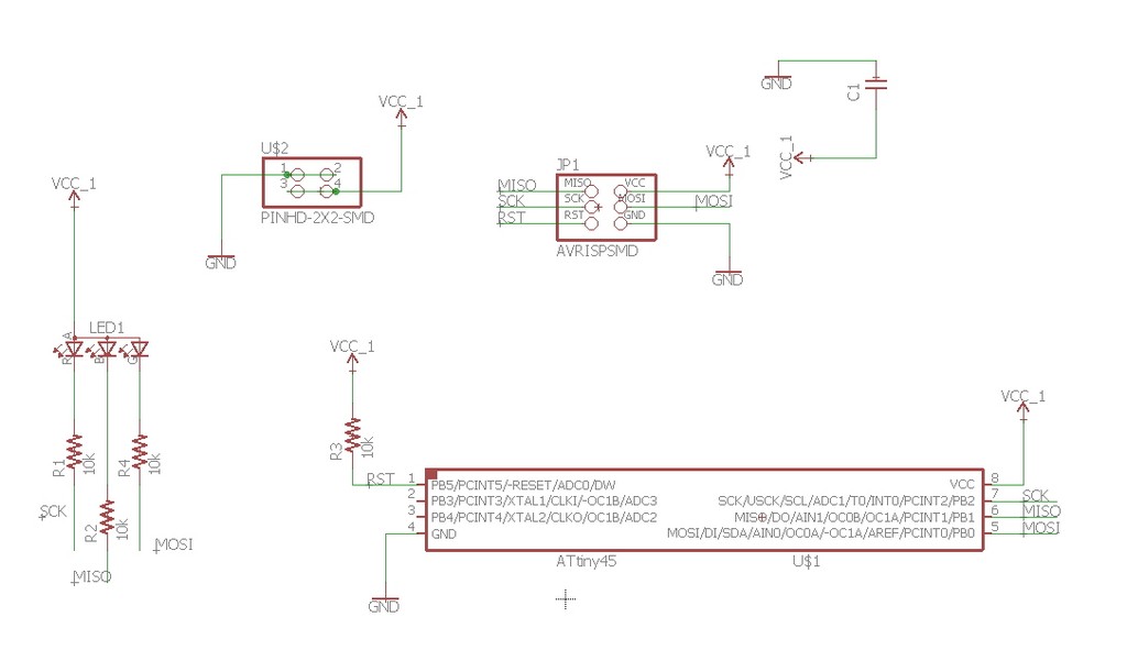
A copy of the Schematic Diagram and Board Diagram - Created using Eagle CAD can be Downloaded as Follow:
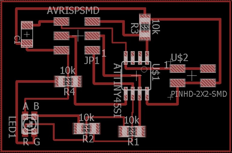
With the creation of the board and schematic files, I then proceed to create the tap mill file and save in a thumbdrive to be used in our PCB2020B CNC router to mill out my board and stuffed it with the following components. The Details processes of the etch.tap file generation already covered in exercise 06, would not be repeated here. Please refer to the following link exercise 06 for how to use PCB2020B CNC Router and etch.tap file generation.
My RGB LED ATtiny85 Board Components List
- One Attiny45/85 microcontroller
- One 2x3 Programming Header
- One 1x2 Pin Header
- One 3 x 499 ohm Resistor
- One 10K ohm Resistor
- One 1uF Capacitor
- One RGB LED
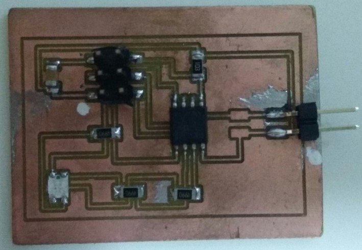
I then go ahead to stuff my board and produced my RGB LED ATtiny85 board as shown in the following snapshot.
Coding for my RGB Led ATtiny Board
With Reference to the DataSheet for ATtiny85 MCU I first defined the pins for the Red, Green and Blue led and set these bits as output in Arduino IDE Environment.
     //RGB LED - random colors

     int redPin = PB2;
     int greenPin = PB0;
     int bluePin = PB1;

     void setup()
     {
     // drive the LED to be outputs:
	   pinMode(redPin, OUTPUT);
	   pinMode(greenPin, OUTPUT);
	   pinMode(bluePin, OUTPUT);
      }
Following that I specified in the loop() function to loop randomly repeatedly various colours from RED, GREEN, BLUE, WHITE, YELLOW, CYAN and PURPLE with a delay of 3 seconds. This is achieved with digitalWrite() function by putting HIGH or LOW to either RED, GREEN or BLUE pin or combination of any 2 or all pins as illustrated in the following codes break down.
     void loop()
     {

	 // Turn LED Red On
	   digitalWrite(redPin, HIGH);
	   digitalWrite(greenPin, LOW);
	   digitalWrite(bluePin, LOW);

	   delay(3000);

	 // Turn LED Green On

	   digitalWrite(redPin, LOW);
	   digitalWrite(greenPin, HIGH);
	   digitalWrite(bluePin, LOW);

	   delay(3000);

	 // Turn LED Blue on

	   digitalWrite(redPin, LOW);
	   digitalWrite(greenPin, LOW);
	   digitalWrite(bluePin, HIGH);

	   delay(3000);

	 // Turn LED Red and Green on - Yellow

	   digitalWrite(redPin, HIGH);
	   digitalWrite(greenPin, HIGH);
	   digitalWrite(bluePin, LOW);

	   delay(3000);

	 // Turn Green and Blue on - Cyan

	   digitalWrite(redPin, LOW);
	   digitalWrite(greenPin, HIGH);
	   digitalWrite(bluePin, HIGH);

	   delay(3000);

	 // Turn Red and Blue on - Purple

	   digitalWrite(redPin, HIGH);
	   digitalWrite(greenPin, LOW);
	   digitalWrite(bluePin, HIGH);

	   delay(3000);

	// Turn all LEDs on - White

	   digitalWrite(redPin, HIGH);
	   digitalWrite(greenPin, HIGH);
	   digitalWrite(bluePin, HIGH);

	   delay(3000);
      }
The program code can be downloaded here.
The above coding was then compile and uploaded into my RGB LED ATtiny 85 board using FABISB board as the programmer and a record of the background processes is as documented as follow:
    Sketch uses 902 bytes (11%) of program storage space. Maximum is 8,192 bytes.
    Global variables use 9 bytes (1%) of dynamic memory, leaving 503 bytes for local variables. Maximum is 512 bytes.
    C:\Users\Guan\AppData\Local\Arduino15\packages\arduino\tools\avrdude\6.3.0-arduino9/bin/avrdude -CC:\Users\Guan\AppData\Local\Arduino15\packages\arduino\tools\avrdude\6.3.0-arduino9/etc/avrdude.conf -v -pattiny85 -cusbtiny -Uflash:w:C:\Users\Guan\AppData\Local\Temp\arduino_build_618531/testingRGB.ino.ino.hex:i

     avrdude: Version 6.3, compiled on Jan 17 2017 at 12:00:53
         Copyright (c) 2000-2005 Brian Dean, http://www.bdmicro.com/
         Copyright (c) 2007-2014 Joerg Wunsch

         System wide configuration file is "C:\Users\Guan\AppData\Local\Arduino15\packages\arduino\tools\avrdude\6.3.0-arduino9/etc/avrdude.conf"

         Using Port                    : usb
         Using Programmer              : usbtiny
     avrdude: usbdev_open(): Found USBtinyISP, bus:device: bus-0:\\.\libusb0-0001--0x1781-0x0c9f
         AVR Part                      : ATtiny85
         Chip Erase delay              : 400000 us
         PAGEL                         : P00
         BS2                           : P00
         RESET disposition             : possible i/o
         RETRY pulse                   : SCK
         serial program mode           : yes
         parallel program mode         : yes
         Timeout                       : 200
         StabDelay                     : 100
         CmdexeDelay                   : 25
         SyncLoops                     : 32
         ByteDelay                     : 0
         PollIndex                     : 3
         PollValue                     : 0x53
         Memory Detail                 :

                                  Block Poll               Page                       Polled
           Memory Type Mode Delay Size  Indx Paged  Size   Size #Pages MinW  MaxW   ReadBack
           ----------- ---- ----- ----- ---- ------ ------ ---- ------ ----- ----- ---------
           eeprom        65    12     4    0 no        512    4      0  4000  4500 0xff 0xff
           flash         65     6    32    0 yes      8192   64    128 30000 30000 0xff 0xff
           signature      0     0     0    0 no          3    0      0     0     0 0x00 0x00
           lock           0     0     0    0 no          1    0      0  9000  9000 0x00 0x00
           lfuse          0     0     0    0 no          1    0      0  9000  9000 0x00 0x00
           hfuse          0     0     0    0 no          1    0      0  9000  9000 0x00 0x00
           efuse          0     0     0    0 no          1    0      0  9000  9000 0x00 0x00
           calibration    0     0     0    0 no          1    0      0     0     0 0x00 0x00

         Programmer Type : USBtiny
         Description     : USBtiny simple USB programmer, http://www.ladyada.net/make/usbtinyisp/
     avrdude: programmer operation not supported

     avrdude: Using SCK period of 10 usec
     avrdude: AVR device initialized and ready to accept instructions

     Reading | ################################################## | 100% 0.00s

     avrdude: Device signature = 0x1e930b (probably t85)
     avrdude: NOTE: "flash" memory has been specified, an erase cycle will be performed
         To disable this feature, specify the -D option.
     avrdude: erasing chip
     avrdude: Using SCK period of 10 usec
     avrdude: reading input file "C:\Users\Guan\AppData\Local\Temp\arduino_build_618531/RGB_LED.ino.ino.hex"
     avrdude: writing flash (902 bytes):

     Writing | ################################################## | 100% 1.34s

     avrdude: 902 bytes of flash written
     avrdude: verifying flash memory against C:\Users\Guan\AppData\Local\Temp\arduino_build_618531/RGB_LED.ino.ino.hex:
     avrdude: load data flash data from input file C:\Users\Guan\AppData\Local\Temp\arduino_build_618531/RGB_LED.ino.ino.hex:
     avrdude: input file C:\Users\Guan\AppData\Local\Temp\arduino_build_618531/RGB_LED.ino.ino.hex contains 902 bytes
     avrdude: reading on-chip flash data:

     Reading | ################################################## | 100% 1.09s

     avrdude: verifying ...
     avrdude: 902 bytes of flash verified

     avrdude done.  Thank you.
A short video of my RGB-LED board cycling through the various colors is a shown:
From here for my attempt to understand how does Prof. Neil's coding works, I proceeded to use the RGB RGB LED C code in Atmel Studio 7.
From the first part of the c-code, I understood that it is using PWM to control the timing of changing of RGB colour with a delay of 25us and defined pin PB1 as out put for RED LED, PB0 as GREEN LED, PB2 as BLUE LED.
   #include <avr/io.h>
   #include <util/delay.h>

   #define output(directions,pin) (directions |= pin) // set port direction for output
   #define set(port,pin) (port |= pin) // set port pin
   #define clear(port,pin) (port &= (~pin)) // clear port pin
   #define pin_test(pins,pin) (pins & pin) // test for port pin
   #define PWM_delay() _delay_us(25) // PWM delay

   #define led_port PORTB
   #define led_direction DDRB
   #define red (1 << PB1)
   #define green (1 << PB0)
   #define blue (1 << PB2)

   int main(void) {
   //
   // main
   //
   unsigned char count, pwm;
   //
   // set clock divider to /1
   //
   CLKPR = (1 << CLKPCE);
   CLKPR = (0 << CLKPS3) | (0 << CLKPS2) | (0 << CLKPS1) | (0 << CLKPS0);
   //
   // initialize LED pins
   //
   set(led_port, red);
   output(led_direction, red);
   set(led_port, green);
   output(led_direction, green);
   set(led_port, blue);
   output(led_direction, blue);
Next, I read further to understand the c-code main function- where using PWM of 25us delay to loop from OFF to RED 'ON' to GREEN 'ON' to BLUE 'ON' to OFF continuously.
   int main(void) {
   //
   // main
   //
   unsigned char count, pwm;
   //
   // set clock divider to /1
   //
   CLKPR = (1 << CLKPCE);
   CLKPR = (0 << CLKPS3) | (0 << CLKPS2) | (0 << CLKPS1) | (0 << CLKPS0);
   //
   // initialize LED pins
   //
   set(led_port, red);
   output(led_direction, red);
   set(led_port, green);
   output(led_direction, green);
   set(led_port, blue);
   output(led_direction, blue);
   //
   // main loop
   //
   while (1) {
      //
      // off -> red
      //
      for (count = 0; count < 255; ++count) {
         clear(led_port,red);
         for (pwm = count; pwm < 255; ++pwm)
            PWM_delay();
         set(led_port,red);
         for (pwm = 0; pwm < count; ++pwm)
            PWM_delay();
         }
      //
      // red -> green
      //
      for (count = 0; count < 255; ++count) {
         set(led_port,red);
         clear(led_port,green);
         for (pwm = count; pwm < 255; ++pwm)
            PWM_delay();
         clear(led_port,red);
         set(led_port,green);
         for (pwm = 0; pwm < count; ++pwm)
            PWM_delay();
         }
      //
      // green -> blue
      //
      for (count = 0; count < 255; ++count) {
         set(led_port,green);
         clear(led_port,blue);
         for (pwm = count; pwm < 255; ++pwm)
            PWM_delay();
         clear(led_port,green);
         set(led_port,blue);
         for (pwm = 0; pwm < count; ++pwm)
            PWM_delay();
         }
      //
      // blue -> on
      //
      for (count = 0; count < 255; ++count) {
         set(led_port,blue);
         clear(led_port,green);
         clear(led_port,red);
         for (pwm = count; pwm < 255; ++pwm)
            PWM_delay();
         set(led_port,blue);
         set(led_port,green);
         set(led_port,red);
         for (pwm = 0; pwm < count; ++pwm)
            PWM_delay();
         }

      //
      // on -> off
      //
      for (count = 0; count < 255; ++count) {
         set(led_port,blue);
         set(led_port,green);
         set(led_port,red);
         for (pwm = count; pwm < 255; ++pwm)
            PWM_delay();
         clear(led_port,blue);
         clear(led_port,green);
         clear(led_port,red);
         for (pwm = 0; pwm < count; ++pwm)
            PWM_delay();
         }
      }
   }
With that I then modified the PWM delay to 60us and complie and build the solution in Atmel Studio 7 and had the background processes recorded as follow:
   ------ Build started: Project: GccApplication3, Configuration: Debug AVR ------
   Build started.
   Project "GccApplication3.cproj" (default targets):
   Target "CoreBuild" in file "C:\Program Files (x86)\Atmel\Studio\7.0\Vs\Compiler.targets" from project "c:\users\guan\Documents\Atmel Studio\7.0\GccApplication3\GccApplication3\GccApplication3.cproj" (target "Build" depends on it):
   Using "RunCompilerTask" task from assembly "C:\Program Files (x86)\Atmel\Studio\7.0\Extensions\Application\AvrGCC.dll".
    Task "RunCompilerTask"
    Shell Utils Path C:\Program Files (x86)\Atmel\Studio\7.0\shellUtils
    C:\Program Files (x86)\Atmel\Studio\7.0\shellUtils\make.exe all --jobs 8 --output-sync
    make: Nothing to be done for 'all'.
    Done executing task "RunCompilerTask".
    Using "RunOutputFileVerifyTask" task from assembly "C:\Program Files (x86)\Atmel\Studio\7.0\Extensions\Application\AvrGCC.dll".
    Task "RunOutputFileVerifyTask"
        Program Memory Usage  : 428 bytes   5.2 % Full
        Data Memory Usage     : 0 bytes   0.0 % Full
    Done executing task "RunOutputFileVerifyTask".
    Done building target "CoreBuild" in project "GccApplication3.cproj".
    Target "PostBuildEvent" skipped, due to false condition; ('$(PostBuildEvent)' != '') was evaluated as ('' != '').
    Target "Build" in file "C:\Program Files (x86)\Atmel\Studio\7.0\Vs\Avr.common.targets" from project "c:\users\guan\Documents\Atmel Studio\7.0\GccApplication3\GccApplication3\GccApplication3.cproj" (entry point):
     Done building target "Build" in project "GccApplication3.cproj".
     Done building project "GccApplication3.cproj".

    Build succeeded.
     ========== Build: 1 succeeded or up-to-date, 0 failed, 0 skipped ==========
Following that I proceed to upload the solution to my RGB-LED Board with the background processes in Atmel-Studio captured as below:
  avrdude.exe: Version 5.10, compiled on Jan 19 2010 at 10:45:23
             Copyright (c) 2000-2005 Brian Dean, http://www.bdmicro.com/
             Copyright (c) 2007-2009 Joerg Wunsch

             System wide configuration file is "C:\WinAVR-20100110\bin\avrdude.conf"

             Using Port                    : lpt1
             Using Programmer              : usbtiny
             AVR Part                      : ATtiny85
             Chip Erase delay              : 4500 us
             PAGEL                         : P00
             BS2                           : P00
             RESET disposition             : possible i/o
             RETRY pulse                   : SCK
             serial program mode           : yes
             parallel program mode         : yes
             Timeout                       : 200
             StabDelay                     : 100
             CmdexeDelay                   : 25
             SyncLoops                     : 32
             ByteDelay                     : 0
             PollIndex                     : 3
             PollValue                     : 0x53
             Memory Detail                 :

                                      Block Poll               Page                       Polled
               Memory Type Mode Delay Size  Indx Paged  Size   Size #Pages MinW  MaxW   ReadBack
               ----------- ---- ----- ----- ---- ------ ------ ---- ------ ----- ----- ---------
               eeprom        65     6     4    0 no        512    4      0  4000  4500 0xff 0xff
                                      Block Poll               Page                       Polled
               Memory Type Mode Delay Size  Indx Paged  Size   Size #Pages MinW  MaxW   ReadBack
               ----------- ---- ----- ----- ---- ------ ------ ---- ------ ----- ----- ---------
               flash         65     6    32    0 yes      8192   64    128  4500  4500 0xff 0xff
                                      Block Poll               Page                       Polled
               Memory Type Mode Delay Size  Indx Paged  Size   Size #Pages MinW  MaxW   ReadBack
               ----------- ---- ----- ----- ---- ------ ------ ---- ------ ----- ----- ---------
               signature      0     0     0    0 no          3    0      0     0     0 0x00 0x00
                                      Block Poll               Page                       Polled
               Memory Type Mode Delay Size  Indx Paged  Size   Size #Pages MinW  MaxW   ReadBack
               ----------- ---- ----- ----- ---- ------ ------ ---- ------ ----- ----- ---------
               lock           0     0     0    0 no          1    0      0  9000  9000 0x00 0x00
                                      Block Poll               Page                       Polled
               Memory Type Mode Delay Size  Indx Paged  Size   Size #Pages MinW  MaxW   ReadBack
               ----------- ---- ----- ----- ---- ------ ------ ---- ------ ----- ----- ---------
               lfuse          0     0     0    0 no          1    0      0  9000  9000 0x00 0x00
                                      Block Poll               Page                       Polled
               Memory Type Mode Delay Size  Indx Paged  Size   Size #Pages MinW  MaxW   ReadBack
               ----------- ---- ----- ----- ---- ------ ------ ---- ------ ----- ----- ---------
               hfuse          0     0     0    0 no          1    0      0  9000  9000 0x00 0x00
                                      Block Poll               Page                       Polled
               Memory Type Mode Delay Size  Indx Paged  Size   Size #Pages MinW  MaxW   ReadBack
               ----------- ---- ----- ----- ---- ------ ------ ---- ------ ----- ----- ---------
               efuse          0     0     0    0 no          1    0      0  9000  9000 0x00 0x00
                                      Block Poll               Page                       Polled
               Memory Type Mode Delay Size  Indx Paged  Size   Size #Pages MinW  MaxW   ReadBack
               ----------- ---- ----- ----- ---- ------ ------ ---- ------ ----- ----- ---------
               calibration    0     0     0    0 no          2    0      0     0     0 0x00 0x00

             Programmer Type : USBtiny
             Description     : USBtiny simple USB programmer, http://www.ladyada.net/make/usbtinyisp/
  avrdude.exe: programmer operation not supported

  avrdude.exe: Using SCK period of 10 usec
  CMD: [ac 53 00 00] [ff fe 53 00]
  avrdude.exe: AVR device initialized and ready to accept instructions

  Reading | CMD: [30 00 00 00] [00 30 00 1e]
  CMD: [30 00 01 00] [00 30 00 93]
  ################CMD: [30 00 02 00] [00 30 00 0b]
  ################################## | 100% 0.00s

  avrdude.exe: Device signature = 0x1e930b
  CMD: [50 00 00 00] [00 50 00 62]
  avrdude.exe: safemode read 1, lfuse value: 62
  CMD: [50 00 00 00] [00 50 00 62]
  avrdude.exe: safemode read 2, lfuse value: 62
  CMD: [50 00 00 00] [00 50 00 62]
  avrdude.exe: safemode read 3, lfuse value: 62
  avrdude.exe: safemode: lfuse reads as 62
  CMD: [58 08 00 00] [00 58 08 df]
  avrdude.exe: safemode read 1, hfuse value: df
  CMD: [58 08 00 00] [00 58 08 df]
  avrdude.exe: safemode read 2, hfuse value: df
  CMD: [58 08 00 00] [00 58 08 df]
  avrdude.exe: safemode read 3, hfuse value: df
  avrdude.exe: safemode: hfuse reads as DF
  CMD: [50 08 00 00] [00 50 08 ff]
  avrdude.exe: safemode read 1, efuse value: ff
  CMD: [50 08 00 00] [00 50 08 ff]
  avrdude.exe: safemode read 2, efuse value: ff
  CMD: [50 08 00 00] [00 50 08 ff]
  avrdude.exe: safemode read 3, efuse value: ff
  avrdude.exe: safemode: efuse reads as FF
  avrdude.exe: NOTE: FLASH memory has been specified, an erase cycle will be performed
             To disable this feature, specify the -D option.
  CMD: [a0 01 fc 00] [00 a0 01 ff]
  CMD: [a0 01 fd 00] [00 a0 01 ff]
  CMD: [a0 01 fe 00] [00 a0 01 ff]
  CMD: [a0 01 ff 00] [00 a0 01 ff]
  avrdude.exe: erasing chip
  CMD: [ac 80 00 00] [00 ac 80 00]
  avrdude.exe: Using SCK period of 10 usec
  CMD: [ac 53 00 00] [00 ac 53 00]
  avrdude.exe: reading input file "c:\users\guan\Documents\Atmel Studio\7.0\GccApplication3\GccApplication3\Debug\GccApplication3.hex"
  avrdude.exe: writing flash (428 bytes):

  Writing | CMD: [4c 00 00 00] [9a 4c 00 00]
  #######CMD: [4c 00 20 00] [f7 4c 00 20]
  #######CMD: [4c 00 40 00] [f7 4c 00 40]
  ########CMD: [4c 00 60 00] [f7 4c 00 60]
  #######CMD: [4c 00 80 00] [f3 4c 00 80]
  ########CMD: [4c 00 a0 00] [17 4c 00 a0]
  #######CMD: [4c 00 c0 00] [cf 4c 00 c0]
  ###### | 100% 0.42s

  avrdude.exe: 428 bytes of flash written
  avrdude.exe: verifying flash memory against c:\users\guan\Documents\Atmel Studio\7.0\GccApplication3\GccApplication3\Debug\GccApplication3.hex:
  avrdude.exe: load data flash data from input file c:\users\guan\Documents\Atmel Studio\7.0\GccApplication3\GccApplication3\Debug\GccApplication3.hex:
  avrdude.exe: input file c:\users\guan\Documents\Atmel Studio\7.0\GccApplication3\GccApplication3\Debug\GccApplication3.hex contains 428 bytes
  avrdude.exe: reading on-chip flash data:

  Reading | ################################################## | 100% 0.24s

  avrdude.exe: verifying ...
  avrdude.exe: 428 bytes of flash verified

  CMD: [50 00 00 00] [cf 50 00 62]
  avrdude.exe: safemode read 1, lfuse value: 62
  CMD: [50 00 00 00] [00 50 00 62]
  avrdude.exe: safemode read 2, lfuse value: 62
  CMD: [50 00 00 00] [00 50 00 62]
  avrdude.exe: safemode read 3, lfuse value: 62
  avrdude.exe: safemode: lfuse reads as 62
  CMD: [58 08 00 00] [00 58 08 df]
  avrdude.exe: safemode read 1, hfuse value: df
  CMD: [58 08 00 00] [00 58 08 df]
  avrdude.exe: safemode read 2, hfuse value: df
  CMD: [58 08 00 00] [00 58 08 df]
  avrdude.exe: safemode read 3, hfuse value: df
  avrdude.exe: safemode: hfuse reads as DF
  CMD: [50 08 00 00] [00 50 08 ff]
  avrdude.exe: safemode read 1, efuse value: ff
  CMD: [50 08 00 00] [00 50 08 ff]
  avrdude.exe: safemode read 2, efuse value: ff
  CMD: [50 08 00 00] [00 50 08 ff]
  avrdude.exe: safemode read 3, efuse value: ff
  avrdude.exe: safemode: efuse reads as FF
  avrdude.exe: safemode: Fuses OK
  avrdude.exe done.  Thank you.
A short clip of my RGB-LED board cycling through the various colorswith pwm delay set to 60 us is a shown:
The program code can be downloaded here.
LED Array Using Charlieplexing
As mentioned earlier one of the output device that I would most probably be using in my final project would be LED lighting. So next, I would like continue to explore the way of LED light array using Charlieplexing. In particularly to gauge whether the intensity and brightness on the LED light array is enough for my application.
What is Charlieplexing?
Charlieplexing is a technique for driving a multiplexed display in which relatively few I/O pins on a microcontroller are used to drive an array of LEDs. The method uses the tri-state logic capabilities of microcontrollers in order to gain efficiency over traditional multiplexing.
I made reference to the class site, where Neil's LED array board uses ATtiny44 our local instructor Mr Steven Chew previous year design of a LED array board using ATtiny45 for the making of exact same Charlieplexing board using ATtiny 85 MCU. So based on the fact that we need to drive 5 x 4 = 20 LEDs, all the 5 available I/O lines from ATtiny85 will be used thus leaving just the Reset pin unused. That would free it up when the ISP header need to re-program the board.
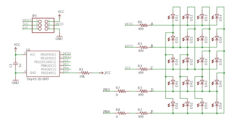
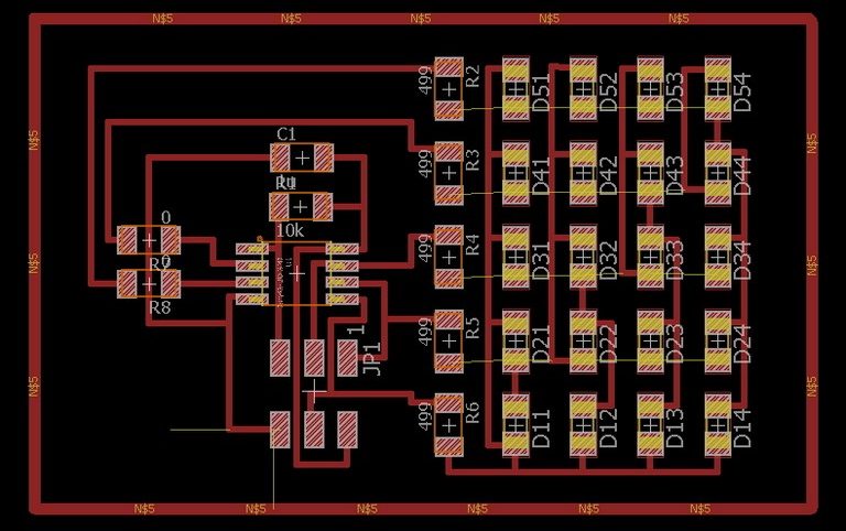
Schematic diagram and board design for my Charliplexing ATtiny85 Board
A screenshot of both Schematic and Board design Diagrams for my Charlieplexing Board are as shown:
Components List of my LED Charlieplexing ATtiny85 Board
- One Attiny45/85 microcontroller
- One 2x3 Programming Header
- One 1x2 Pin Header
- One 5 x 499 ohm Resistor
- One 10K ohm Resistor
- One 1uF Capacitor
- 20 LEDs
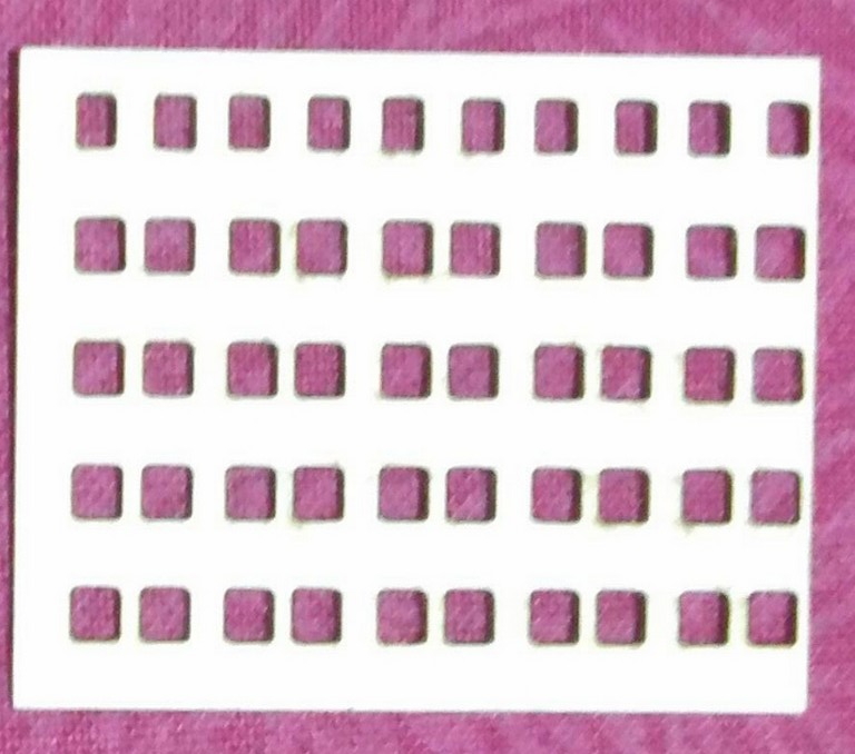
Instead of making the LED Array board in a double sided PCB, I have created a paper mask for the LED Array. Using the board layout for in Eagle CAD I exported the pattern as png file and edited to remove unwanted pcb traces and components pad leaving only the pads for the pull-up resistors and LEDs. Next, I laser cut the pattern for the pull-up resistors and LEDs.
With the board file I then proceed to mill out the Charlieplexing board using our PCB2020B CNC router; and then proceeded to stuff the board with the paper mask and using the components as listed in the components list.
After much efford and hours of eyes straining soldering work on the Charlieplexing Array Board, I have produced my own array board as illustrated below:
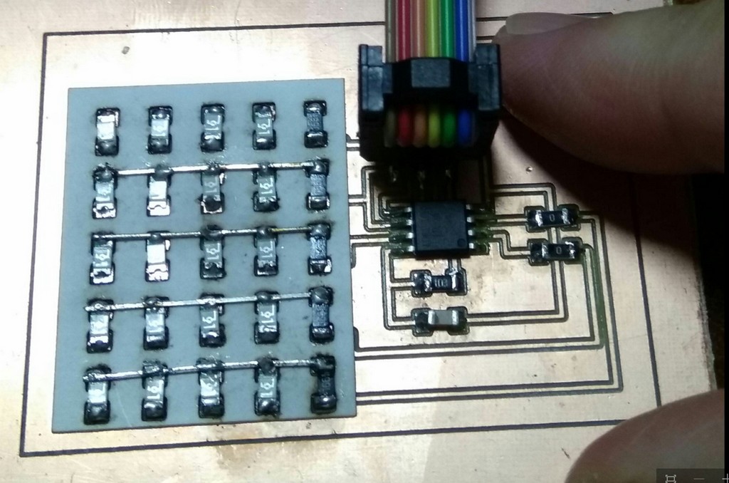
After stuffed my board, I proceed connect it up for programming and testing.
A copy od Schematic diagram and board diagram files for my RGB-LED Board are as follow:
After that, I proceed to modify Prof. Neil's Charlieplexing C Code in Atmel Studio 7; with some minor modification.(As we are using ATtiny 85 rather than the original coding with is for ATtiny44). In particular the modification of the following section of the C code:
#define led_delay() _delay_ms(10) // LED delay

#define led_port PORTB
#define led_direction DDRB

#define A (1 << PB0) // row 1
#define B (1 << PB1) // row 2
#define C (1 << PB2) // row 3
#define D (1 << PB3) // row 4
#define E (1 << PB4) // row 5
//I have futher edited my code to test whether a reduce of LED scrolling speed.
      led_cycle(10,100);
      led_cycle(10,150);
      led_cycle(10,200);
      }
   }
Essentially, what the code led_cycle(10,100) does- was to cycle through LEDs 10 times based on the direction and row defined with a delay of 100ms. Similarly, for led_cycle(10,150) but with a delay of 150ms. Lastly, led_cycle(10,200) would mean to make the LED cycle through 10 times with a delay of 200ms....
From there, I then proceed to build the solution and upload using programmer as usual in Atmel Studio7 and a short clip is of my labour of hardwork as shown.
A copy of the modiied code for my LED Array (Charlieplexing) can be found here.
My Reflection
Once again this week I am finding myself running out of time. My study this week gotta end here with the c coding modification and testing in Atmel Studio7. I think if time permit I would like to learn another output device that most likely I am going to use in my Final Process - DC Motor to power up fan/s in my laptop stand.
This week after much hussle and guidance from out local instructor Mr Rodney Dorville, we finally able to catch the technic to using the CNC2020B PCB milling Machine. The technic is essential to milling out pcb borad of acceptable quality, aside to the dependant of cutter sharpness. With this technic, I am more confidence that the next board that we are going to mill will be of usable.
After soldered of 20 LEDs, 5 pull up resistors for LED, ATtiny85, capacitor, connection pins, etc in my Charlieplexing board and able to got the board to work, I have gained significant confidence that I can make a simple PCB using the technic learnt this far.
References
- FabISP: Programming
- Programming an ATtiny w/ Ardurino 1.6 - ATtiny45/85 vs. an Arduino Board
- NewbieHack - Microcontroller Tutorial - A Beginners Guide
- Writing the First Program to Turn On an LED and Transferring the Program into the Microcontroller
- AVR Programming–Tutorial 2–Hands on Programmers Notepad & MAKE file creation
- Four PWM Outputs from the ATtiny85
- The Makefile
- The pinouts of the most popular AVR processors.
- Timers in Compare Mode – Part I and Timers in Compare Mode – Part II