Exercise 07 Computer-Controlled Machining
This week Assignment Requirement
- Make something BIG using Signvec SK2030 CNC Router.
Introduction
Making something big to a System Administrator like me, seems to be a something so distance and impossible to me; as I don't normally make anything. As mentioned at the my introduction, mostly we would just go for the pruchase of off the shelf readily avaialble mechandises.
I was briefed by our local instructor, that we need to use 3D CAD to generate the 3Ddesign, where we are not supposed to use any nails, screws or glue to put the component parts together. So immediately came to my mind is to make something using wood joint technique for assemble the pieces together into a whole furniture. Then I remembered, in one of the preparation lesson, Mr Rodney and Mr Steven Chew ever pointed to us on the learning of Autodesk Fusion 360 to create some standard flatpack furniture. As a start, I would perhaps just try to make that simple stool that we learnt to CAD using AutoDesk's Fusion 360. With reference to the link, I follow exactly to CAD out exact replica copy of my own flatpack standard stool just like the one shown in the following video:Video showing how to CAD something BIG using AutoDesk's Fuison 360.
Following that, I went on to follow another youtube video to learn to CAD my own book shelf.
Although three of us, Steven Foo, Jeff Teo and I are from School of Design Singapore Polytechnic, but our jobs nature dont't normally required us to do any CAD design. This is a turf that we would never have enter and are not familiar with. I am taking this opportunity to learn and got myself familiarize with using Autodesk's Fusion 360. The only way for me to learn something within such as short period of time is to learn through watching a video and try to learn to how to produce the exact same replica of 3D Model design thought in the video. At least that is what I thought.
Difficulty in designing
As mentioned earlier, 3D CAD Design is not our trade at all. Even with reference from the two video, we are still facing the challenge of how to find the Kerf to compensate for the excess of material being take away by the router cutting process. Based on week 3 study of kerf for laser cutter, we tried to replicate some sort of test kits to find the best fitting for a simple slot and tab design. I also found some useful information base on the following:
- Ben Heck’s CNC Router Tutorial
- CNC Panel Joinery Notebook
- Simple knock down stool made from plywood (flat pack)
Signvec SK2030 CNC Router Familiarization and Kerf Finding.
How to use the handheld controller to control the Signvec SK2030 CNC Router
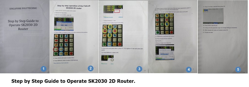
Probably, it would take weeks if we were to go through the entire user manual to find out how to go about and using this Signvec SK2030 CNC Router. When we approached our senior Mr Tham Heng Loong, he had kindly referred us to an in house manual "Singapore Polytechnic- Step by Step Guide to Operate SK2030 2D Router". That serve as a start, at least for us to begins our work on the familiarization of the operation of this CNC router.
As a start, all of us were learning together on the finding of Kerf for this CNC router which was fixed with a cutter diammeter of D=6mm flat Endmill and we were using some waste wood of thickness, measured to be t=8.7mm.
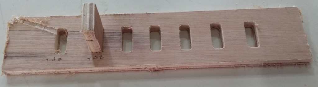
As illustrated in the cut out, we found that for the thickess, t=8.7mm test plug, the best fitting slot is the one that an additional 0.8mm larger than the actual drew dimenison. Our local instructor then commented that we will be using stock of 1/2 inch thick ply, it is best that we could do our study based ontest kit made of stock of ply thickness that we going to use. As such, Jeff redrawn another test set using exact ply thcikness measure to be, t~11.61mm.
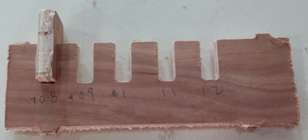
With the above testing, we determined that the Kerf for our CNC router with flat carbide endmil of diammeter, D=6mm is Kerf=0.8mm In Short all the dimension of slot need to be compensated for this kerf value in both the x and y direction, in order to obtain the desired best fitting.
Study of CNC router spindle speed, feedrate, chipload
Based on our previous experience with another CNC machine - Charyl2U by Mechamac which provide a general guideline for 6mm diammeter flat Endmil on softwood which recommended a spindle speed of ranging from 8000rpm to 24000rpm, Jeff and I decided to play safe and using the lower range of the recommended spindle speed of 8000rpm to begins our study.
As we did not refer to the machine user manual and cutter specification for further clarifaction, we would stick to this spindle speed and did a study on the effect of the variation and also the output timing by varying the spindle speed, speed, speed rate. All the studies were performed using the 11.61mm thick test kit.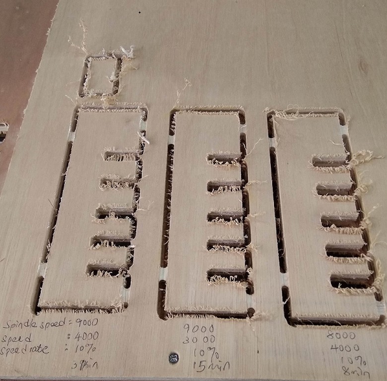
Based on the study, we can conclude that for a slower speed at constant 10% speed rate, the CNC router would take a longer time to cut out the same test kit. If we decided to use spindle speed of 8000rpm, probably we could vary the speed rate to achieve a fast cutting speed. Further to that, when spindle speed is set to 8000rpm, router produced less noise and vibration. So in order to achive a balance between speed and duration, we have decided to fix our spindle speed at 8000rpm and increase that speed rate to as high as 75% to improve on the through put and reduce the duration.
I then made reference to CNC Routing Basics: Toolpaths and Feeds ‘n Speeds to get a better understanding of feeds and speeds relationship. I found in particularly usefule the following paragraphs extracted from the page on:
Calculating Feeds and Speeds
Below is a formula for calculating feed rate:
ChipLoad x CutterDiameter x NumberOfFlutes x SpindleSpeed = FeedRate
Where chipload is the amount of material cut per tooth (feed per tooth). Feed rate is the surface speed of the cutting tool in inches per min, spindle speed is the rotational speed of the cutting tool in revolutions per min, number of flutes and cutter diameter are determined by your tool. In this case they are ¼ inch and 2 flutes. Depending on the size of your bit, the chipload for plywood is between 0.005 inches 0.01 inches per tooth. For small bits below 1/8 inch start with 0.005 and increase from it there. For bits 1/4 inch and larger you will probably not break anything starting out at 0.01.
The size of the chipload or feed per tooth is a very important factor in machining, larger chips are able to pull away more heat. Smaller chips are easier on your machine and tools but can cause too much heat. You want to make chips that when dropped fall to the floor rather than become dust that stays in the air.
When trying to hone in on your feeds and speeds with a new bit, guess as best you can using the feeds and speeds formula and touch the bit as soon as it stops spinning after making a few cuts (remember: safety first), it should be warm, maybe a little hot to the touch, but it should not burn you. If it is too hot, increase the feed rate or lower the spindle speed. Look at the quality of the edge after the cut has been completed. If it is wavy, that’s tool chatter and you should decrease your feed rate or increase your spindle speed.
Use your ears too, the tool should sound good when cutting … trust your gut.For our case, the spindle speed=8000rpm, assuming a chipload=0.01 inch/min,cutter diammeter=6mm, number of flute for our flat endmill=2. With all these information we can determine an appropriate feedrate/ speed as in our CNC router called it.
Max Feedrate = (0.01 inch/min) x 2 x 8000rpm= 160inch/min or 4,064mm/minSo when we set our cutting speed = 4000mm/min, speed rate= 75%, it is actually within the allowable feedrate. The feedrate we are using= 3000mm/min
Preparing Fusion 360 for milling
Before we send our design to CNC router for milling, there is a preparation step that need to be done. That is the CAM process in Fusion 360 to generate the Gcode for milling.
The file created in fusion 360 CAM process is in .tap format. With reference to CAM in Fusion 360 and Introduction to CAM/Toolpaths. I proceed to generate the .tab format gcode needed for the milling.
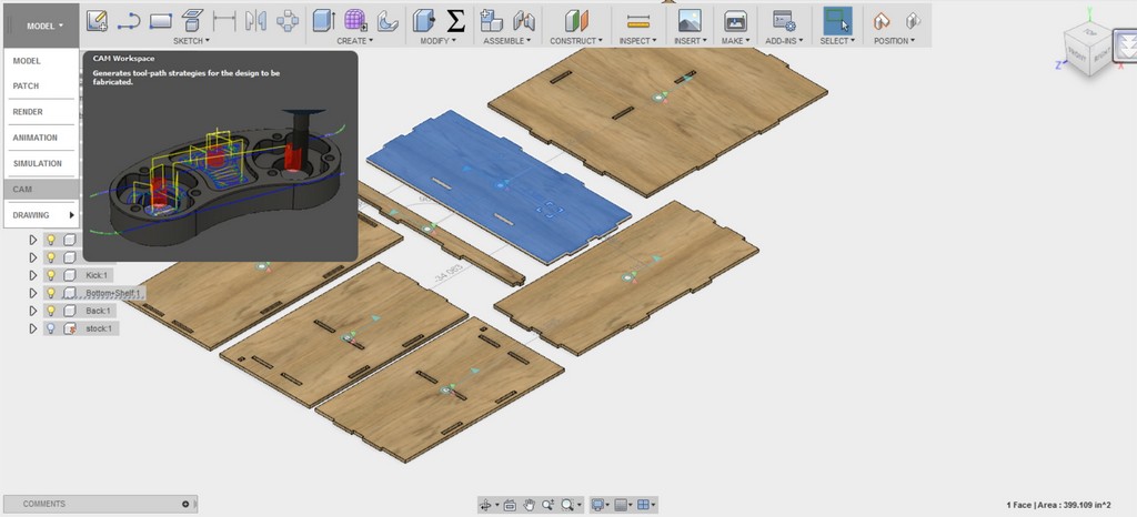
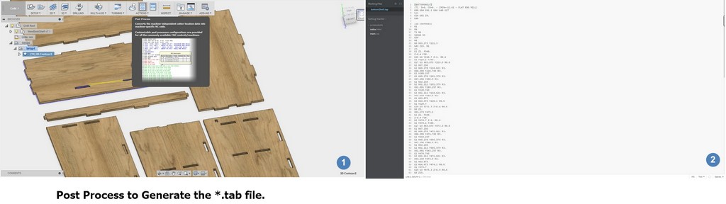
From the model design processes I switched to CAM processes in Fusion 360.
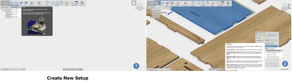
- Within the CAM processes, I run a new setup from the setup tab and selected the reference, Z direction, and the reference x axis.
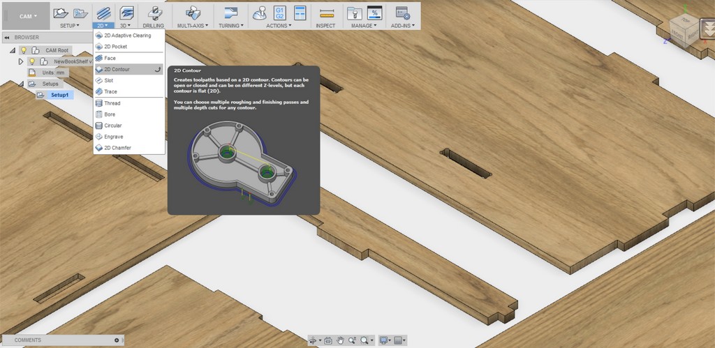
- I then selected 2D Contour from the 2D dropdown menu and under Tool > Pick 6mm Flat endmil
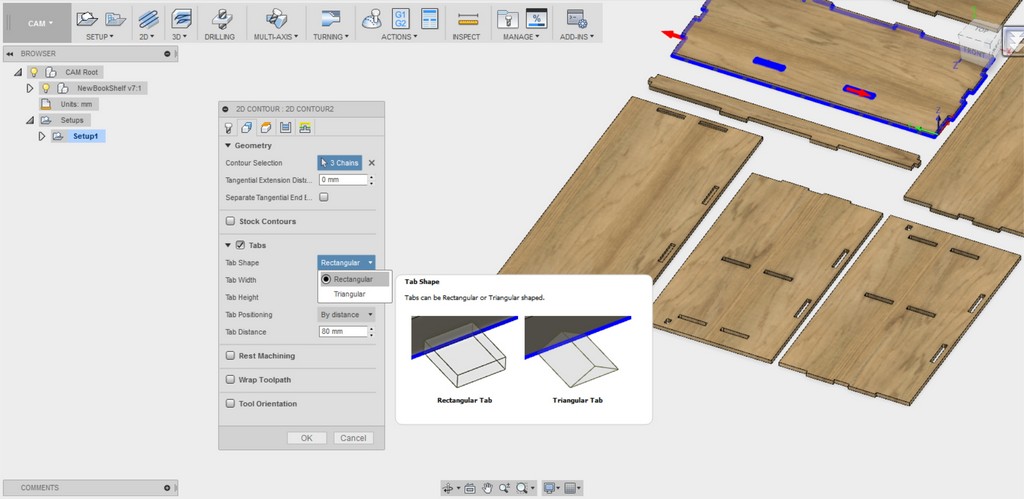
- Under Geometry > Select cutting profile, pick the direction for inner cut under contour selection, insert tabs for mill to prevent stock from flying out
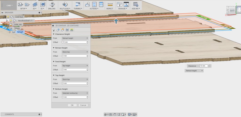
- I kept Under Height and Passes, all as per default settings
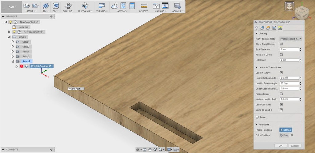
- I then define the entry position for the mill (optional) in the "Linking" to speed fix the nearest entry point for the cutter to start cutting.
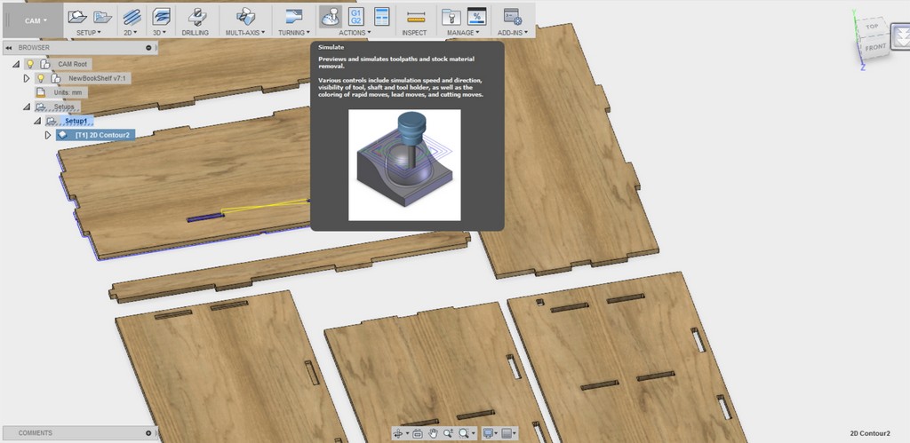
- From there I then performed a Simulation and observed the toolpath generated and stock materials removal within Fusion 360 CAM processes
- When everything is well in place, I then selected Post Process to create the gcode needed for milling (Will be choosing Generic Mach 3 Mill for my milling machine). File with extension *.tap will be created.
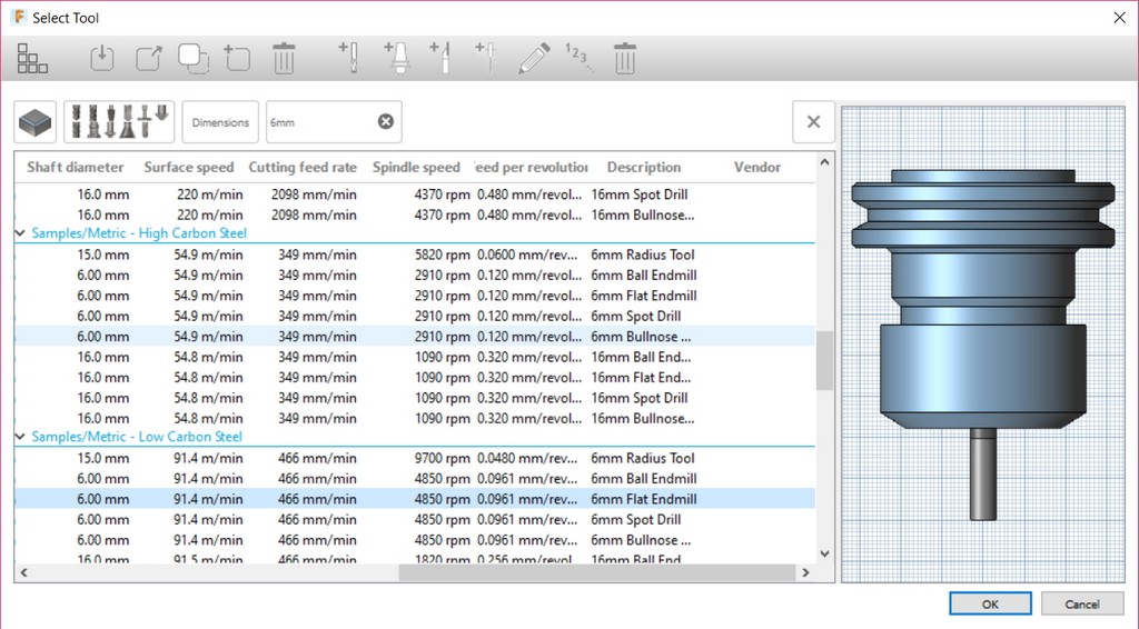
Note: Recommended spindle speed=4850rpm and cuting feedrate=466mm/min
Conversion of Gcode for JG
Upon created the tap file from Fusion 360, we are required to use the CNC_CHANGE (JG) Program to convert the *.tap file created *.JG file (which is the CNC controller readable format).
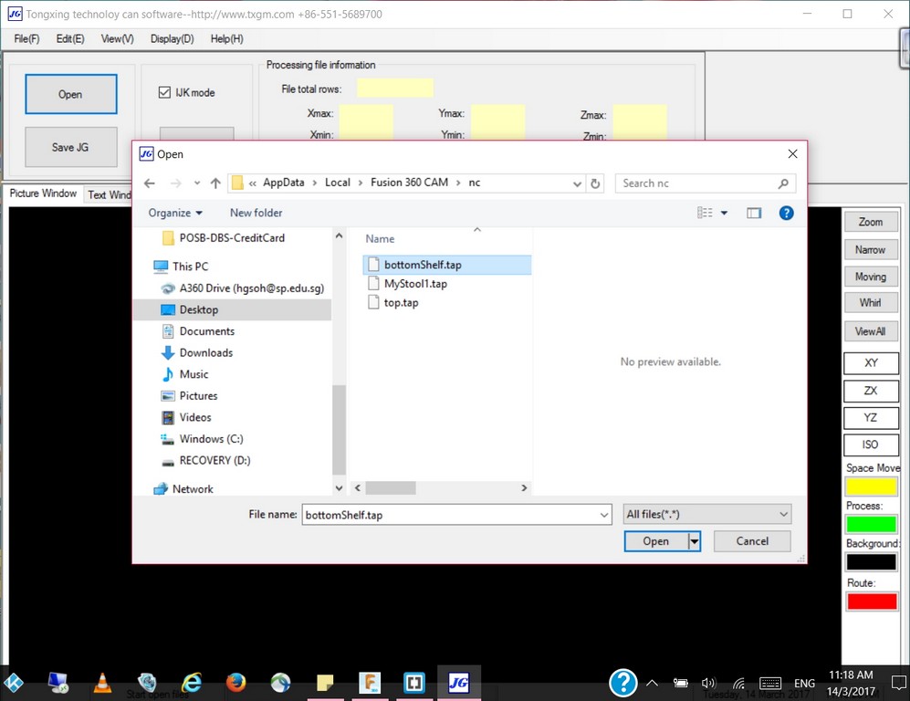
Upon opened up of the *.tap file created, click save JG and we are ready to save the JG file into a thumb/flash drive to be open at the Signvec CNC controller for actual cutting.
Millling out of the Flat Pack Stool
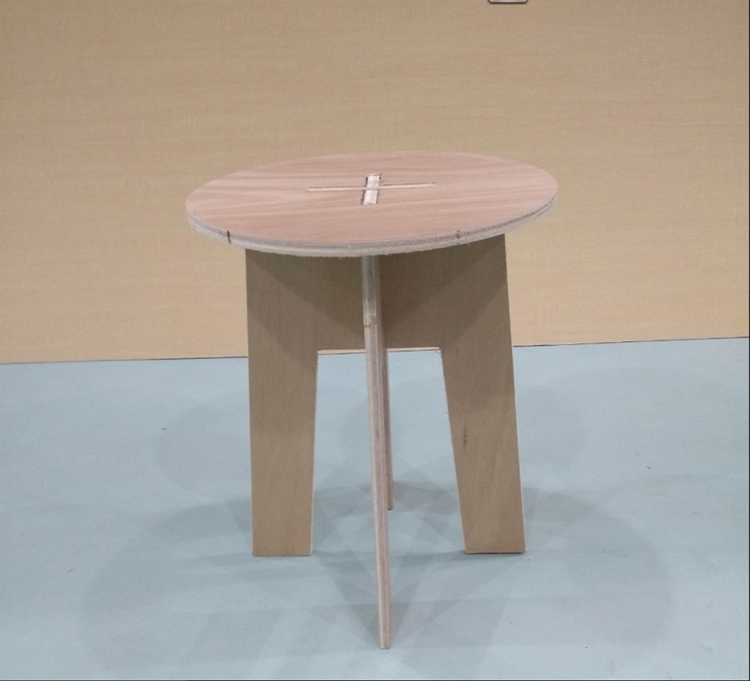
With the JG file transfered to the Signvec SK2030 CNC Router thorugh the machine controller, I started to do my first milling of myflatpackstool and captured the milling process video as follow:
Valla! After a couple days of hardwork - I produced myflatpackstool and got it assembled as follow:
Millling out of the My Book Shelf
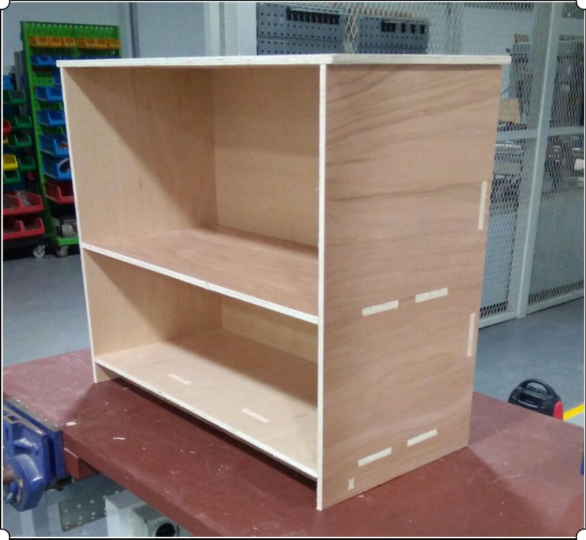
With the success in milling out my flat pack stool and experience gained, I am more confident of the conversion from *.tap file to *.JG file and transfer of file to Signvec SK2030 CNC Router. I then proceed to do the same and milled out my book shelf and recoded the milling out processes as follow:
After a long wait, as the bookshelf consist of a total of seven components; I finally got my pieces milled out and assembled. As shown a picture of my book shelf is as follow:
Reflections
For my stool cut out I did it with only the inclusion of kerf to obtain the best fitting. I was able to achieve quite a good press even without any dogbone being included. For my book shelf, as the pieces cut out are having quite a numbers of slots and tabs, so I choose to include both the kerf compensation and dogbones at every single corners.
Although, we are rushing and everyweek time don't seem to be on our side; this week Make something BIG exercise seem to be the most fun packed and hectic one. Where we got to learn to use an entirely new CNC router machine, studied the machine characterization to determine the Kerf and lastly how to operate the machine in order to done the actual cutting. But truly it is rather fulfilling and enjoyable experience as we got to really make something useful!
Download Week 7 work files
References
- Folding Stool - 3D CAD rendered video showing the construction of a folding stool
- Folding stool plan
- Simple knock down stool made from plywood (flat pack)