Exercise 06 Electronics Design
This week Assignment Requirements
- Redesgin/redraw the echo hello-world board using Atmel ATtiny 45/85 Processor in place of ATtiny44 processor.
- Add (at least) a button and LED (with current-limiting resistor)
- Check the design rules, mill the board, and test it
- Extra credit: simulate its operation
Introduction
What is Eagle?
EAGLE (Easily Applicable Graphical Layout Editor) is a flexible and expandable EDA schematic capture, PCB layout, autorouter and CAM program. EAGLE is popular among hobbyists because of its freeware license and rich availability of component libraries on the web.
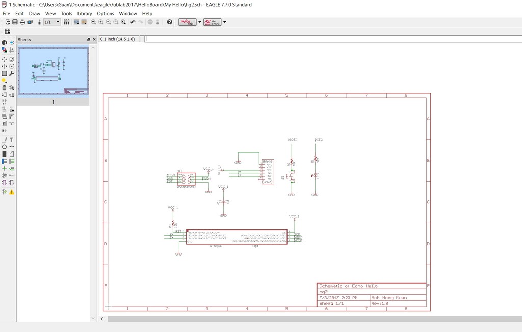
For this week schematic design of the Echo Hello Board, I am still using Autodesk Eagle CAD software"
Using Eagle for Redesign of Echo Hello Board
Eagle is a PCB CAD software. The limitations of the free version are:-
- schematic sheet
- signal layers(top & bottom)
- Board area limited to 100 x 80mm
- Limited to email or forum support
- Use is limited to non-profit applications.
To start using Eagle EDA Software these are the steps:
- Download Eagle software
- Copy Fab.lbr into the lib directory in Eagle.
- Create a new project and add a new schematic with SparkFun PaperFrames found in SparkFun Aesthetics.
- Add components into schematic by using the ADD tool and create connections between them by using the NET tool.
- Name the nets that need to connect together the same name and label it so that the name appears in the diagram
- Switch to the board view and position the components.
- Run the Ratsnest command.
- Use the Route button to manual route the circuit and ripup to remove trace.
- Run a Design Rule Check and correct any mistakes.
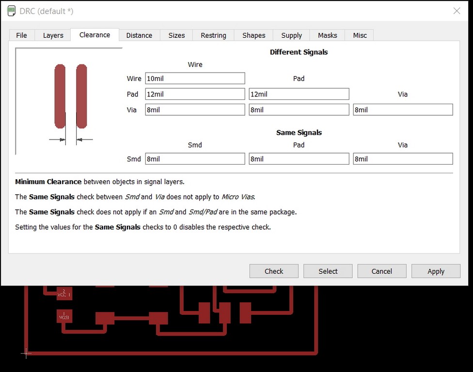
Design Rule Check (DRC)
Design Rule Check is the area of Electronic Design Automation that determines whether the physical layout of a particular chip layout satisfies a series of recommended parameters called Design Rules. The most basic design rules for single layer rules are width and spacing / clearance. A width rule specifies the minimum width of any shape in the design. A spacing (clearance) rule specifies the minimum distance between two adjacent objects. I have used the clearance settings as shown in screenshot below to run a DRC test on my board design and found everything to be fine.
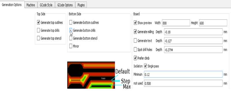
Generating G-Code Output
Eagle CAD can also generate g-code files for generic milling machines. To do this, you need to install the pcb-gcode-setup.ulp. Unzip the pcb-gcode files and save them in the Eagle ULP folder (C:\EAGLE-7.7.0\ulp).
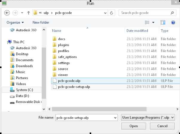
In Eagle Control Panel, under Option/Directories, add the pcb-gcode directory to the ULP section and click OK.
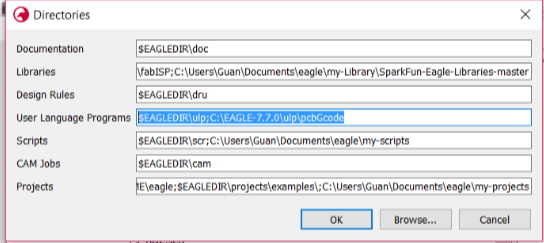
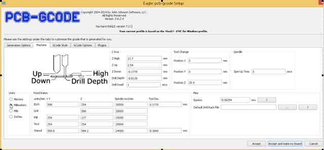
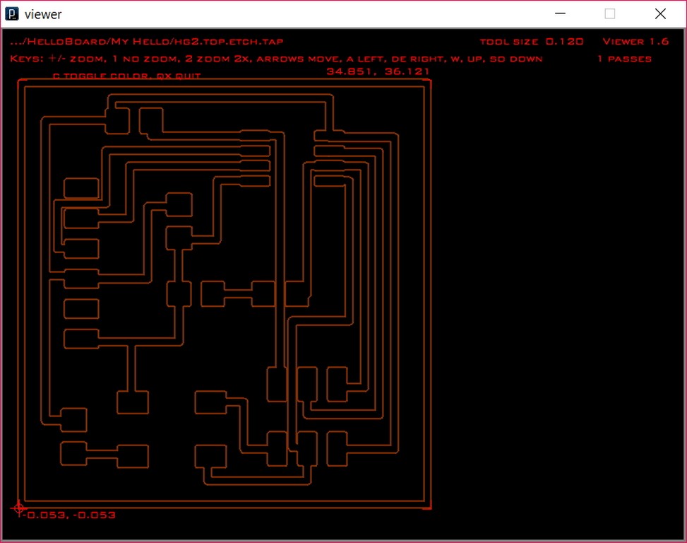
The program will generate a file with the extension .etch.top.
The Milling Process
Following that I proceed to mill my board using a PCB2020B CNC router.
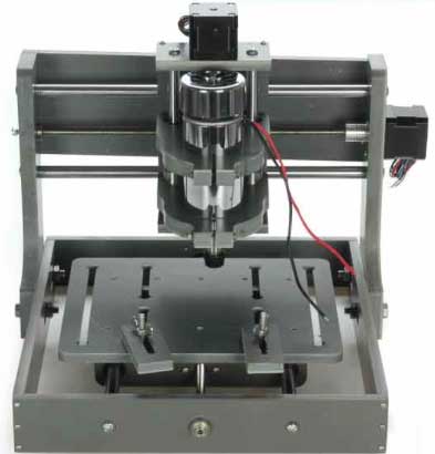
The pcb milling machine that we are using is a CNC 2020B machine. It is an entry level cnc equipment. It is MACH3 compatible system . It has a working area size 200mm(X-axis), 200mm(Y-axis) & 70mm(Z-axis) and equipped with a 300W high speed spindle. The main shaft speed is able to operate from 6000 to 12000rpm/min and the tool diameter range is from 0.3 to 3.175mm. It is powered by 3 stepper motors.
The USB-control board is USBCNC compatible and interfaces between the PC and the Mach-3 controller board. The input for the PCB2020B is a gcode file.
Load the file into the CNC program
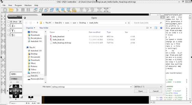
Define the X,Y(Origin) and Z-Zero position using thin sheet of paper testing at least 3 points diagonally across the cutting area.
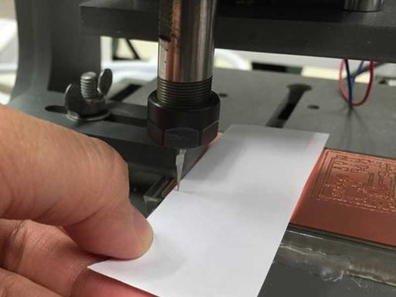
Press the start button to begin milling.
My Echo Hello World Board Components List
- 1x Microcontroller Attiny45 (ATTINY85): IC chip for programmingATiny45 microcontroller (Data Sheet)
- 1x Programming Header J1, 2x3 (AVRISPSMD): to interface the programming of the board
- 1x FTDI Header J2, 1x6 (FTDI-SMD-HEADER): powers the board and allows board to talk to computer
- 1x Resistor 499 (RES-US1206): current limiting resistor so we don't burn out the LED.
- 2x Resistors 10K (RES-US1206): pull-up resistor
- 1x Capacitor 1uF (CAP-US1206): to decouple one part of an electrical network (circuit) from another to remove voltage or signal spikes in electronic circuits.
- 1x LED (LED1206)
- 1x 6mm Switch button (6MM_SWITCH6MM_SWITCH)
Labour of hardwork
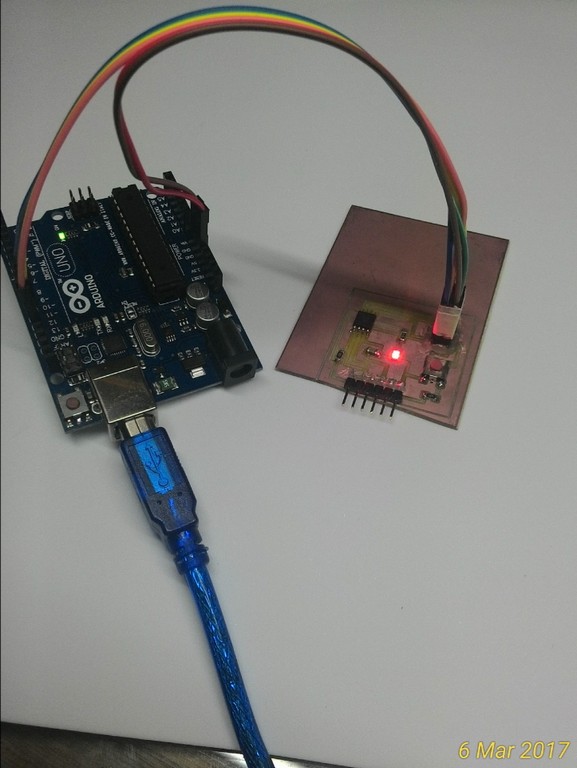
After passed all the short circuit/connectivity test before and after stuffing the board. We proceed solder in the components of the board and my Echo Hello board is as follow:
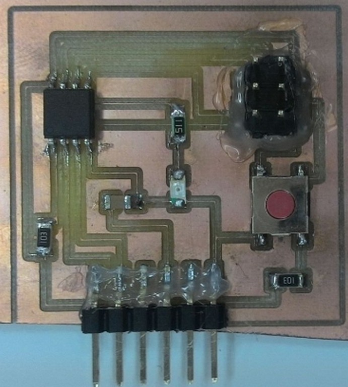
My visual transition issue still affected me quite a bit, although this is my second smt components soldering experience. I think with more practises and getting use to the using of the magnifying glass in future would help.
Testing the board
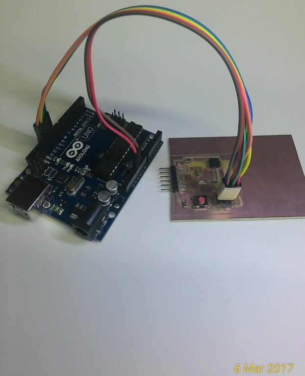
To test the function of the LED light and fuction of the Button we started by programming my Echo Hello Board Using Arduino UNO.
When using Arduino Uno to program other board, it is essential to knew the pins connection. From ATiny45/85 microcontroller (Data Sheet) the connections we used are as follows:
| Uno | ATtiny45/85 |
|---|---|
| 10 | Reset |
| 11 | MOSI |
| 12 | MISO |
| 13 | SCK |
| 5V | VTG |
| GND | GND |
In week 4th, I was using Arduino IDE in Ubuntu, this week I shall be using Arduino IDE in windows platform. As such I would need to add in the support for ATtiny85, and I was following the guide on the link Programming ATtiny85 provided to start using Arduino Uno as ISP.
Programming the Arduino Uno as ISP
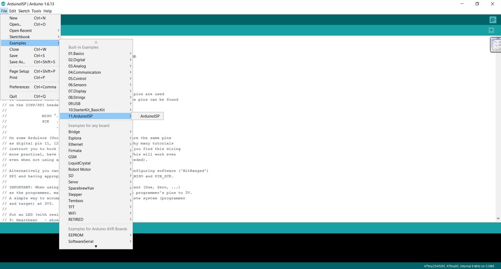
- I execute Arduino IDE and loaded the ArduinoISP programme from Example.
- A new sketch Window will appear with coding which turns Arduino Uno into an ISP
- I then plug in the Arduino Uno through the USB port, compiled and uploaded the sketch
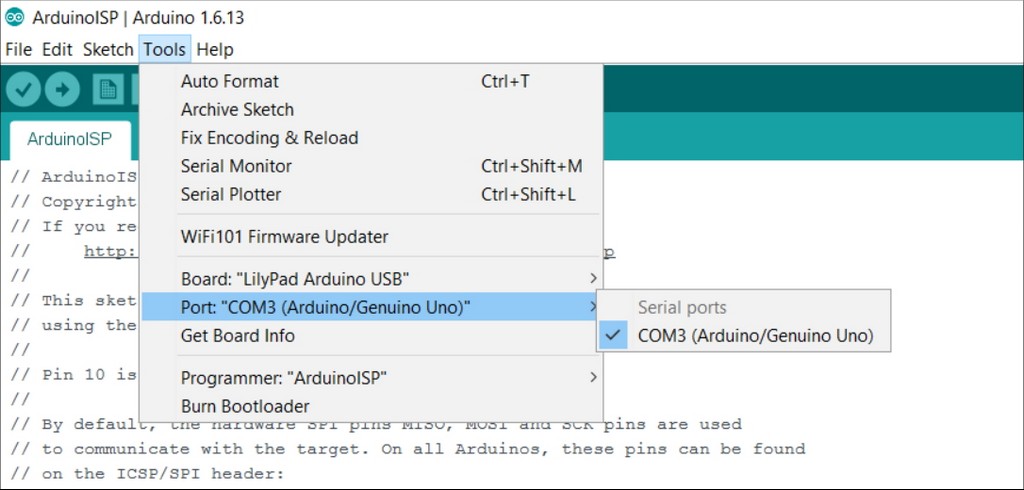
- I double check that the option in Tools -> Board: Arduino/Genuino Uno (Port -> com3) is being selected
- After upload Arduino Uno will be able to communicate with my Echo Hello board
Testing LED operation
- After connected up my Echo Hello board following the above connection for ArduinoISP to ATtiny85 through the 2x3 pins connector
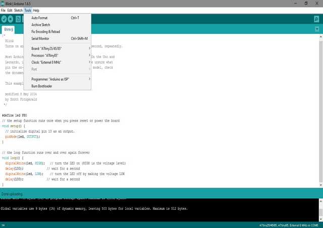
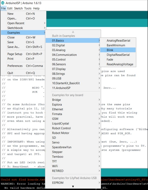
- I opened Arduino IDE, and loaded from Example -> Basics ->Blink (to test the led)
- I also double check and ensure that Tools ->Board: ATtiny25/45/85 was being selected
- Similarly for Processor -> ATtiny85 was selected
- Also for internal Clock -> 8Mhz was set.
- At the same time counter check that Port -> com3 was checked
- In the sketch I had included statement "#define Led_Pin PB1" to define my LED pin.
- I then compiled and uploaded the blink programme into my Echo Hello Board.
- Take note of the pin used for LED then refer to schematic for pin no: PB0 for MOSI, PB1 for MISO, PB2 for SCK and etc above void setup() to declare Led output pin
- Check sketch for PinMode(Led_Pin, OUTPUT), digitalWrite(Led_Pin, HIGH) ON the Led and digitalWrite(Led_Pin, LOW) to OFF the Led
- If all goes well, the ATtiny85’s Led should blink with interval of 1 sec
Testing Button operation
- Similarly, I Loaded the Button program from File Menu->Examples->02.Digitals->Button
- With the connection from Arduino Uno as ISP to ATtiny85 through the 2x3 pins connector and USB to laptop still connected
- With exact same pins connection as in Blink programme, I then modified the sketch to include PB1 as LED pin and PB0 as the Button pin
- All went well, I was able to reset my Echo Hello using ATtiny85’s Led when the button is pressed.
- This video in youtube give some quite helpful step by step information when programming ATtiny 45/85 using an Arduino Uno.
- To include ATtiny45 support into Arduino IDE you can refer to the following url for the information.
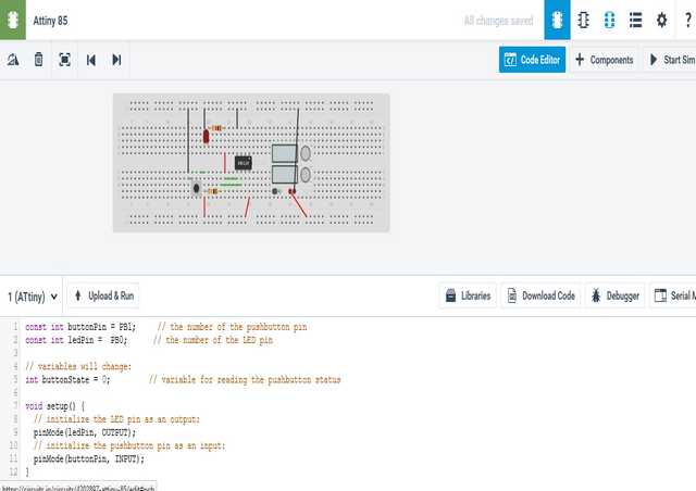
To simulate the Echo Hello Board Operation in Autodesk Circuits
Autodesk Circuit has also included the support for ATtiny MCU in its' components list. I am delighted to find that, it has quite a comprehensive and useful tools to help both newly and experienced users to simulate the function of their circuits; starts even as simple as from bread-boarding to as comprehensive as using oscilloscope and function generator.
There is even a Code Editor to test run the code virtually
When time permit, I would certainly explore more on how to simulate my cuircuit function in future design work. It will be quite a handy tool to work with.
Download Week 6 work files
References
- Electronics Design - Eagle
- How to Install and Setup EAGLE
- Using EAGLE: Schematic
- Using EAGLE: Board Layout