Exercise 04 Electronics Production
Requirement
- Mill out a PCB for In-system Programmer (ISP)
- Stuff the board and solder the components
- Program the board as an ISP
- Test the ISP board built
Making the FabISP Board by Milling Process
The FabISP is an in-system programmer for AVR microcontrollers, designed for production within a FabLab. This FabISP board will allows you to program the microcontrollers on other boards you make later on.
Milling the PCB
Probably because we are inexpereince of PCB making; our local instructor Mr Steven Chew had gave us a detail demonstration on how to use the China made PCB2020B milling machine to mill out a FabISP- based on Prof. Neil FabISP board.
First up is the demonstration of how to clamp the stock FR1 PCB board on a in house designed and fabricated Jig that fittied to the PCB2020B Milling Machine as shown in the following video:
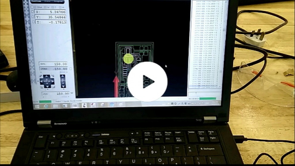
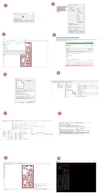
From the demonstration, Steven also showed us how to setup on the CNC USB controller software as illustrate. In particular to teach the machine where is the origin: xy-position of the cut out relative to the PCB stock position and also the spindle with cutter mounted: Z-height position
That was my very first time to use this milling process as a mean of PCB making. I think most of us were used to be using chemical etching process rather than milling process in my early school days. We were so eager to take turn to practise on how to mill out our very first ISP board.
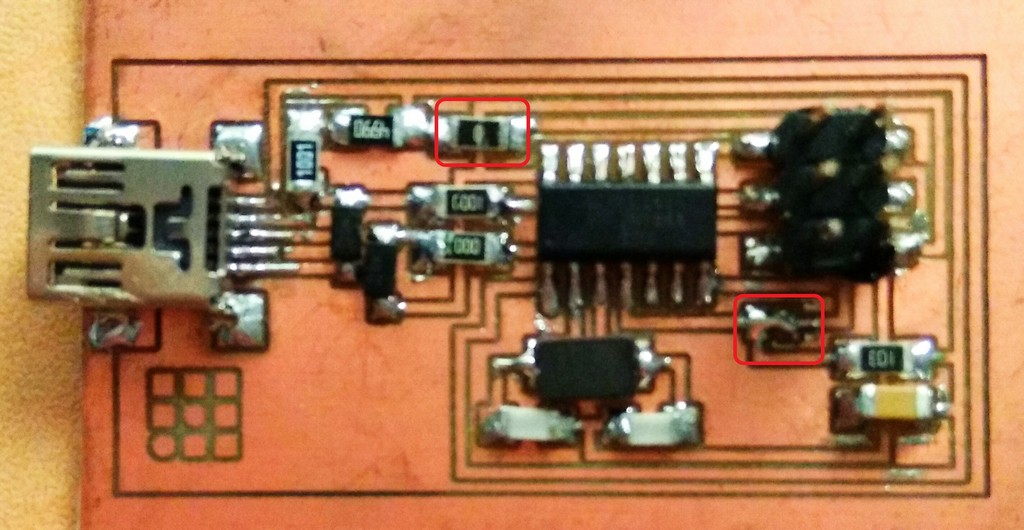
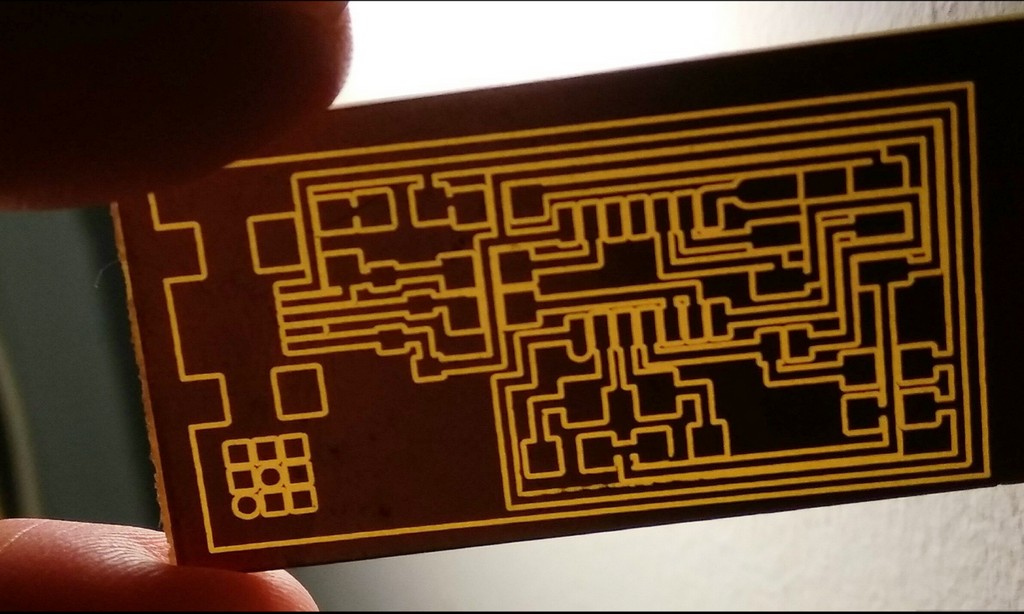
Product of our hard work with PCB2020B PCB milling machine is as shown:
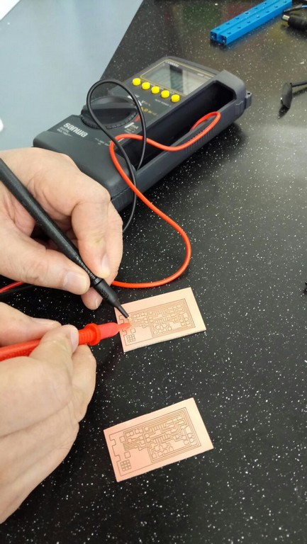
Immediately, after milled out our ISP boards we did some visual inspection and short cuircuit/ connectivity testing using a multimeter.
Stuff Board
First thing on Friday, morning we stormed to our local instructors Mr Rodney and Mr Steven Chew office at 9:30am to request for the components to stuff the board and started to solders the components in immediately at 10:45am; after took care of some admistrative issue back at our office. As mentioned previously, I have no prior experience in soldering of any SMT component before and the very last time that I have made a PCB was more than fifteen years ago.
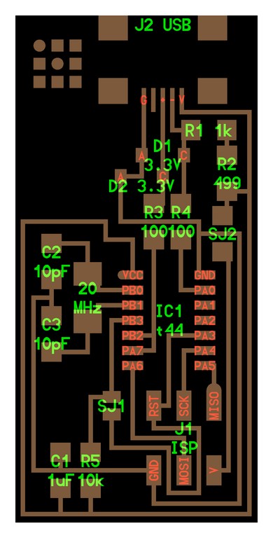
Based on the schematic, the components needed are:
- 1x ATiny44 microcontroller (Data Sheet)
- 1x 1uF capacitor
- 2x 10pF capacitor
- 2x 100 ohm resistor
- 1x 499 ohm resistor
- 1x 1K ohm resistor
- 1x 10K ohm resistor
- 1x 6pin header
- 1x USB connector
- 2x 0 ohm resistors as jumpers
- 1x 20 mHz Crystal
- 2x 3.3V Zener diode
- 1x usb mini cable
- 1x ribbon cable
- two 6 pin connectors
Solder on board the components
After obtained all the clearly labeled components from our instructor Mr Rodney, we started to slowly solder in the components with the aid of super big magnifying glass equipped with lighting.
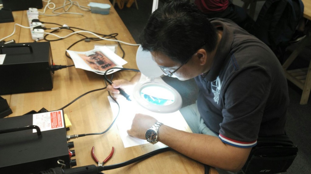
During the soldering of the mini USB connector, I had utilised a little bit too much of solder and caused some of the pins to be shorted together. My peer Louis who is a maker coach had kindly help me to remove some of the excess solder using his steady hands and good eye site. It was really a hard work for me at the age of 45 years old, my vision are no longer as good. Eventhough with the aid of magnifiying glass and lighting, frequently I would still need to remove my spectacle in order to have a better view. I had basically spent the etire Friday afternoon just to solder in most of the components for FabISP.
Things to take note during soldering:
- A temperature of not about 300 degree celcious was being set on the rework and soldering station. The solder should be melted when come in contact with the hot iron and produced a shiny surface to indicate that it is a good join.
- Periodically thinny amount of flux is being utilised to clean the tip of the hot iron to ensure that there was no metal oxide deposited. What the flux does, when you heat a workpiece, is it reacts with these metal oxides that are forming with the temperature and exposure to the air, that tend to interfere with the metal-forming process of soldering. With this chemically cleaned hot iron metal more evenly flow solder can be form as a perfect alloy to form a better contact with the components and copper track/pads on the surface.
- Soldering wick is very useful to soak up excess, unwanted solder from the board.
- Be careful not to create unintentional solder short circuits with adjacent joints. That was what happened when I soldered in the mini USB connector.
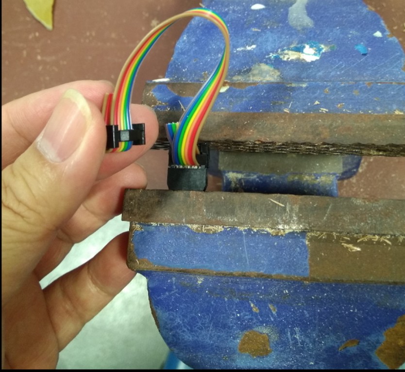
Making of a ribbon cable for programming use
Testing the device
Prior to the testing, our local instructor already prempted us that the possibilty of GND shorted to VCC and causing significant drawing of excess electrical power from the on motherboard USB port and causing laptop to be rebooted. A work around also being proposed which was to get a USB extender that come with external power source and connect up the FABISP board when performing the "Smoke Test". Plug the FabISP into your computer via the mini USB cable. If you do not receive any message, proceed to "Install the necessary software for AVR programming."
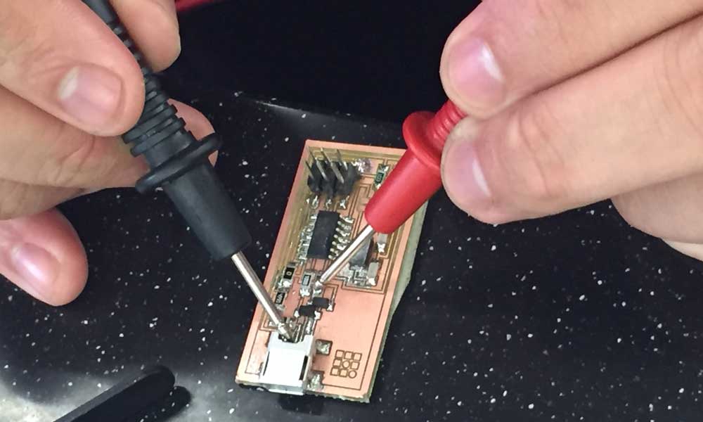
Troubleshooting Short Circuits
- Do a visual inspection of the board and reflow any solder joints that look cold (not shiny and smooth).
- Use a multimeter and check all the connections against each component to make sure that power and ground are not connected. Also check that there is no short on the power line.
Making the FabISP Board- first Step
Based on our instructors previous experience and because of time constraint we all unanimously decided to work on our assignment to produce the FabISP board based on Prof. Neil's design. As I have not much experience in making pcb board, I would satisfy with this for now. In future, I would like to work further on other approach for PCB design.
During the lesson, Prof Neil illustrated on the using of fab modules to generate the machine code for milling. Our instructor demonstration shown another way, which was to use Eagle CAD to read the png traces and board outline to generate the gcode to be fed to our China made PCB2020B milling machine. Aside to the above, our instructor have prepared us to redraw the entire FabISP circuit in Eagle and work toward the generation of the files for pcb milling
In short we have touch base with the following options to create the machine G-code to be fed to our China made PCB2020B milling machine for the milling out of this FabISP board:
- importing the png traces and outline file into fab modules and generating gcode
- using Eagle CAD to read the png traces and board outline and generating gcode
As a good reference for stuff the board, I have downloaded the hello.ISP.44.png FabISP board design, and utilized the FabISP traces file to generate the bmp file (which can be open by Eagle CAD), downloaded the FabISP Board out line for FabISP board from class site.
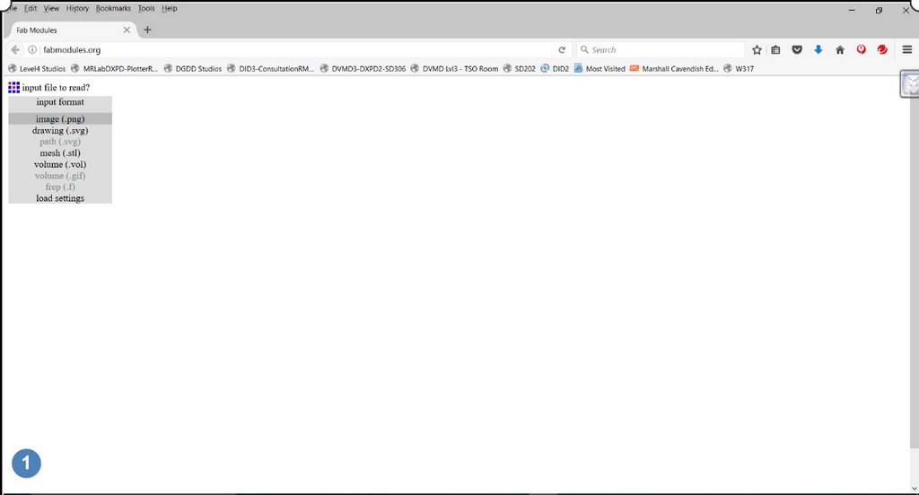
Option 1- PNG to GCode: FabModules.
Using Fabmodule.orgseems to be a rather straight forward way to generate the machine code for by taking in of PNG board design file directly. You can refer to png2MachineCutting and this tutorial videos on how to mill the PCB using fabmodules.
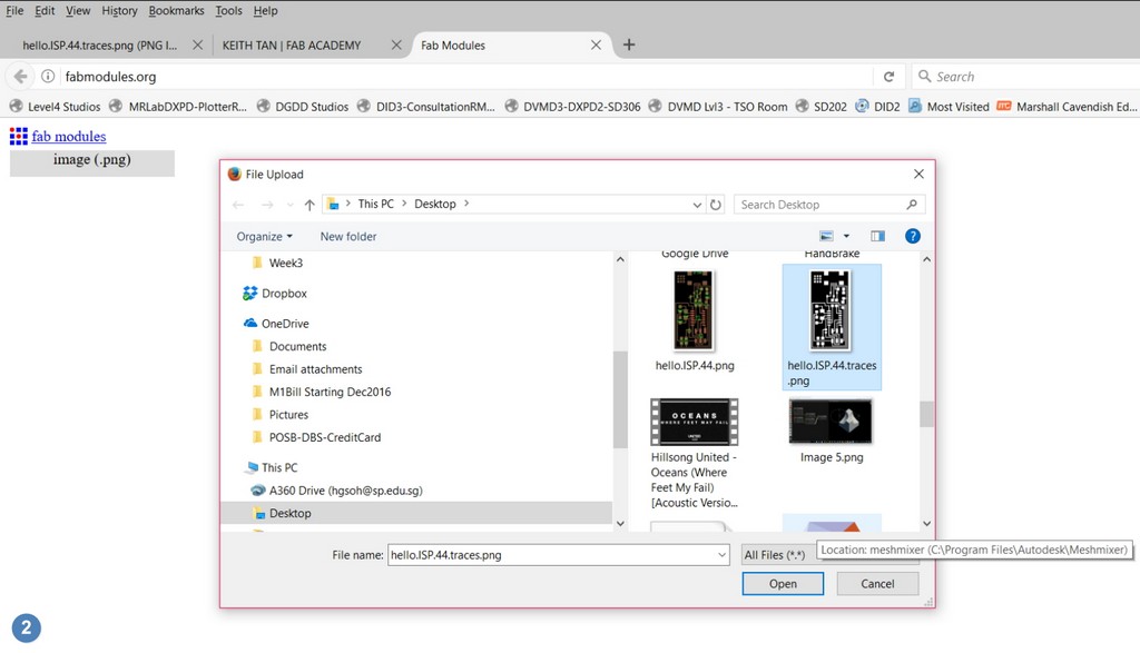
From the video I learnt to utilize online version of Fab module to load from Prof Neil's fabisp traces png file downloaded earlier.
I started with
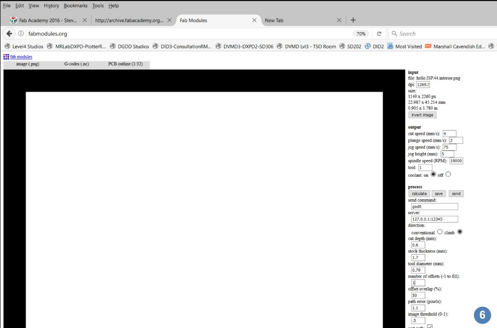
- Go to Fabmodules.org.
- Click on input and select the traces png file.
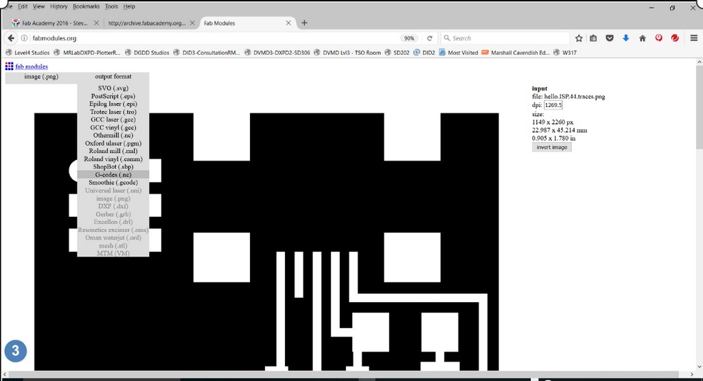
- Click on output and select G-codes (.nc)
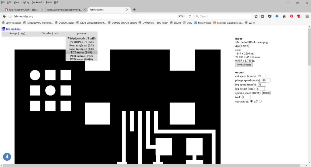
- Click on process and select PCB traces (1/64)
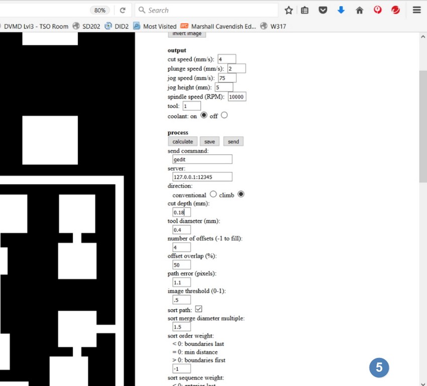
- On the right of the browser window, adjust the cut parameters for the machine.
- Click the calculate button to generate the toolpath.
- Click the save button to save the generated gcode.
- The gcode can now be sent to the pcb-milling machine to cut the pcb.
- Repeat the sequence for the board outline png, using PCB outline (1/32) as the process.
- Cut speed: 4 mm/s
- Plunge speed: 2 mm/s
- Cut depth: 0.18 mm
- Tool diameter: 0.4 mm
- Number of offsets: 4
- Offset overlap: 50%
- Cut speed: 4 mm/s
- Plunge speed: 2 mm/s
- Cut depth: 0.6 mm
- Stock thickness: 1.7 mm
- Tool diameter: 0.79 mm
- Number of offsets: 1
- Offset overlap: 50%
- How To Create a Gerber File Using Eagle
- FabISP: Electronics Production
- What Is Flux? | Soldering
- Learn Simple Surface Mount Soldering in Collin’s Lab
- Common Soldering Problems
- Solder Shorts on a Printed Circuit Board
- FabISP: Programming
- Arduino as an ISP
- AVRDUDE - Using the programmer with AVRDUDE
- FabISP, a fab-able in-system programmer
- Engbedded Atmel AVR® Fuse Calculator
For the FabISP traces, milling on our PCB2020B, I used the following parameters for the nc file:
For the FabISP board outline, milling on our PCB2020B, I used the following parameters for the nc file:
Option 2- PNG to GCode: Eagle CAD to read the png traces
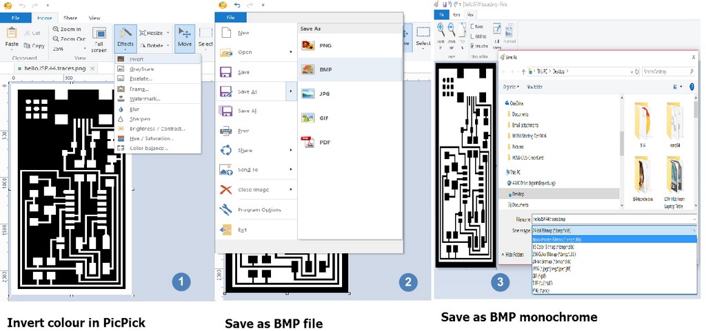
In order to minimise milling tool wear and tear and reduce milling time, I used (both fabmodules and picpick) to convert the hello.ISP.44.traces.png file to bitmap. Then I inverted the output colour to make preparation for milling out the isolation between traces/tracks/pads; rather than mill out all the surrounding copper. This is also to catter for Eagle CAD acceptable file format - bitmap(.bmp). When using fabmodule.org the steps are as illustrated:
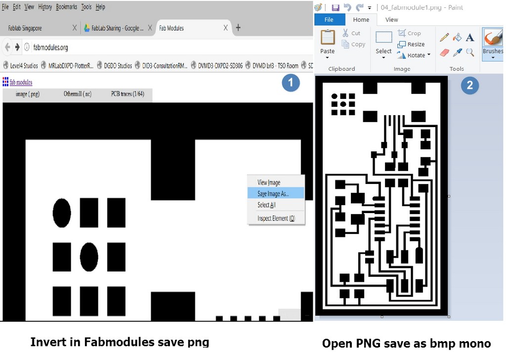
When using picpick I need to further reduce the number of colour to monochrome -2 colours, I used microsoft paint to open and save the exact same bmp file generated. While using fabmodules I can straight away input with the hello.ISP.44.traces.png file and do a invert and save the inverted image as bmp file which is acceptable format in Eagle CAD.
In Eagle CAD open the bitmap format file generated and go through the following steps to generate the gCode for milling ot the PCB in PCB2020B
FabISP Programming
One of the requirement of this exercise is to create a FabISP from the PCB board I have soldered. One way is to have another programmed FabISP or a commercial ISP to flash the firmware on to the newly stuffed and soldered board. An Arduino UNO can be used for this task.
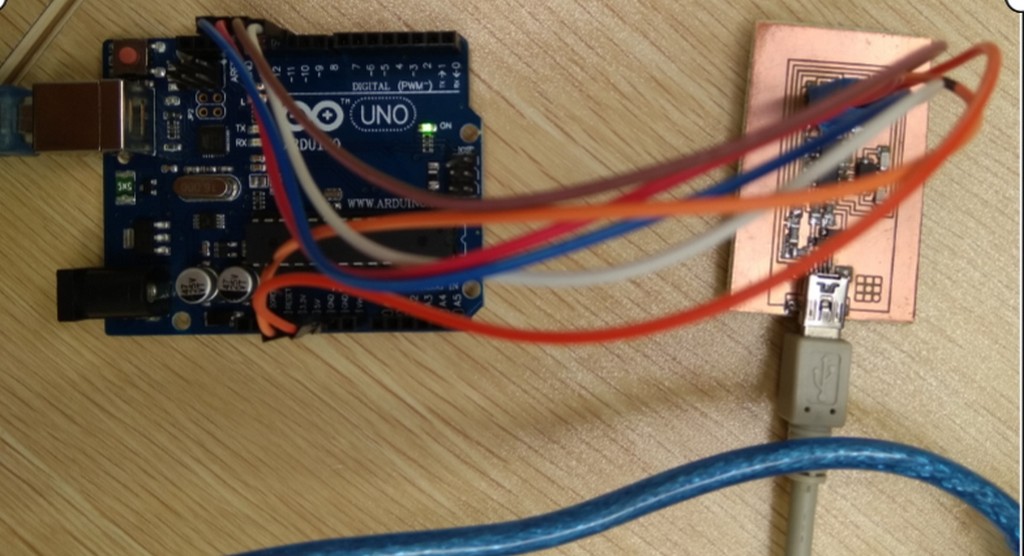
Refer to the connection pins from Uno to FabISP as follow:
| Arduino Uno Pin Connections | FabISP Connections |
|---|---|
| 10 | RST |
| 11 | MOSI |
| 12 | MISO |
| 13 | SCK |
| 5V | VTG |
| GND | GND |
For this exercise I was making reference to Software Installation in Ubuntu. to program my FabISB.
Ubuntu Software Install
Get and install avrdude / GCC software and dependencies:
Open terminal and type:
sudo apt-get install flex byacc bison gcc libusb-dev avrdude
Then type:
sudo apt-get install gcc-avr
- type "y" when asked to do so by your system
Then type:
sudo apt-get install avr-libc
Then type (may already be installed):
sudo apt-get install libc6-dev
Download and Unzip the Firmware
Move to the desktop
cd ~/Desktop
Download the firmware from the Fab Academy Electronics Production page.
wget http://academy.cba.mit.edu/classes/embedded_programming/firmware.zip
Unzip the firmware
unzip firmware.zip
As I am using VMware player and Ubuntu in this exercise rather than using Microsoft Windows, I have also installed Arduino IDE in my Ubuntu Operating Platform. The Arduino IDE software for Ubuntu can be found here: Arduino IDE for Linux 64bits..
Alternatively, can just use the terminal mode to install the Arduino IDE. (Refer to Howto install Arduino in Ubuntu.
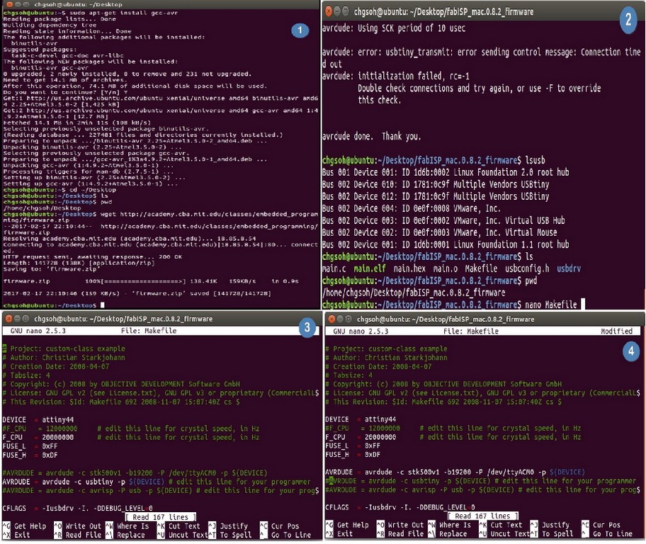
cd to the firmware folder on desktop:
nano Makefile
Edit the AVRDUDE in the Makefile to enable the device that you will be using as your programmer
    AVRDUDE = avrdude -c stk500v1 -b19200 -P /dev/ttyACM0 -p $(DEVICE)
    #AVRDUDE = avrdude -c usbtiny -p $(DEVICE) # edit this line for your programmer
    #AVRDUDE = avrdude -c avrisp2 -P usb -p $(DEVICE) # edit this line for your programmer
Basically the Makefile is a batch file that performing the avrdude command with various options.
Compile the firmware using:
    make clean
    make hex
Establish communication between Uno/FabISP:
sudo make fuse
Flashing the firmware to FabISP:
sudo make program
Avrdude -h is very helpful to know the command lines to use to programme the microcontroller.
avrdude  -h
avrdude: unknown option -- h
Usage: avrdude [options]
Options:
  -p <partno>                Required. Specify AVR device.
  -b <baudrate>              Override RS-232 baud rate.
  -B <bitclock>              Specify JTAG/STK500v2 bit clock period (us).
  -C <config-file>           Specify location of configuration file.
  -c <programmer>            Specify programmer type.
  -D                         Disable auto erase for flash memory
  -i <delay>                 ISP Clock Delay [in microseconds]
  -P <port>                  Specify connection port.
  -F                         Override invalid signature check.
  -e                         Perform a chip erase.
  -O                         Perform RC oscillator calibration (see AVR053).
  -U <memtype>:r|w|v:[:format]
                             Memory operation specification.
                             Multiple -U options are allowed, each request
                             is performed in the order specified.
  -n                         Do not write anything to the device.
  -V                         Do not verify.
  -u                         Disable safemode, default when running from a script.
  -s                         Silent safemode operation, will not ask you if
                             fuses should be changed back.
  -t                         Enter terminal mode.
  -E <exitspec>[,<exitspec>] List programmer exit specifications.
  -x <extended_param>        Pass  to programmer.
  -y                         Count # erase cycles in EEPROM.
  -Y <number>                Initialize erase cycle # in EEPROM.
  -v                         Verbose output. -v -v for more.
  -q                         Quell progress output. -q -q for less.
  -?                         Display this usage.
The commands used on avrdude are:
    avrdude -v -v -c usbtiny -p t44 -e #perform a chip erase
    avrdude -v -v -c usbtiny -p t44 -U lfuse:w:0xff:m -U hfuse:w:0xdf:m -U flash:w:main.hex:i #load main.hex to chip
Verify the ISP is working properly
With the help of my classmates, instructors, and my seniors I was able to load the firmware onto my FabISP. Windows 10 is able to recognize it as USBtiny. Also in the ubuntu environment, I was able to detect the FabISB by listing the usb devices connected as follow:
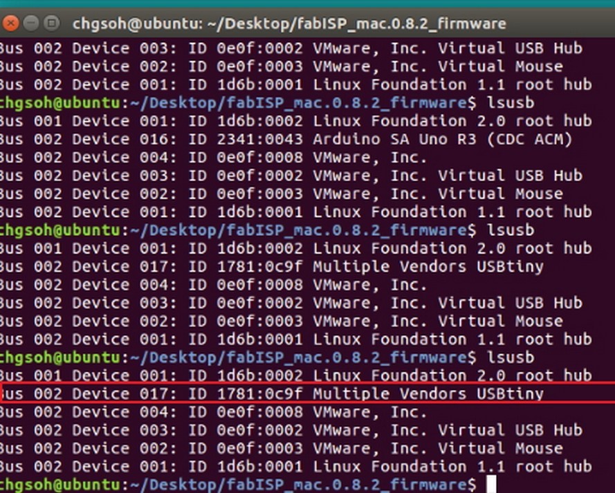
It is hard to be entirely sure that the board is working properly as there is not indication to show that. Some of my classmates occasionally face the problem of unrecognized device even after the firmware has been loaded into the chip successfully. It could be poor connection or soldering. We don't know for sure.
Removing the jumpers
After the firmware was loaded to the microcontroller, we have to remove the SJ1 to prevent further writing onto the chip. We also remove the 0 ohm resister SJ2 to prevent electrical flow. Now we can use this as a programmer to program other boards.