Exercise 03 Computer-controlled Cutting
Requirements
Assignment for this week is to:
- individual assignment: cut something on the vinylcutter design, make, and document a parametric press-fit construction kit, accounting for the lasercutter kerf, which can be assembled in multiple ways.
- group assignment: make laser cutter test part(s), varying cutting settings and slot dimensions.
Laser Cutter/ Engraver machine and Vinyl Cutter
Back at Design School Singapore Polytechnic, we don't have specifically a facility call Fablab. But since year 2007 when School of Design come to fruition we started our very own small scale rapid prototyping studio with one locally assembled large format (4feet x 3feet) 80 Watts CO2 laser mahine, one 50 Watts GCC Spirit Laser machine, two Solido PVC layering 3D printers, 2 Charyl2U CNC machines. Most machines are heavily used by ours diploma students population of about 600 to 800. Because of heavy usage, machines tend to break down rather frequent. As such when some machines which had served their purpose had been disposed off and we had also got our replacments.
What we currently left with 4 units of 60 watts Universal Laser cutters (VLS660 and VLS460), 2 units of Mechamacs Charyl2U CNC, 2 unit of Makerbots Replicators 3D printers. Which are being heavily utilize by School of Design Students day and night to complete their projects.
Apart from Fablab Singapore Facilities at T11C we are very fortunate to have another alternative location to use laser machines (back at our own School Rapid Prototyping Studio). At least that was, what I thought intially, but looking at the students crowd that still coming in- we really have not much time to work on this week assignment after all.
For vinyl cutter, we utilized a readily available Cameo Silhoulete in Fablab to complete our assignment. As our normal stream diploma students are still rushing to complete their final year projects at this period, we would have to compete with our own students in using laser cutters to finish up our this week assignment. So on Thursday afternoon, we decided to work on the vinyl cutter assignment first, while waiting for the availablity of laser cutter.
- VLS Universal VLS 6.60 (60W)
- VLS Universal VLS 4.60 (60W)
- Charyl2U
- Cameo silhouette
- Makerbot Replicator2
Vinyl Cutter
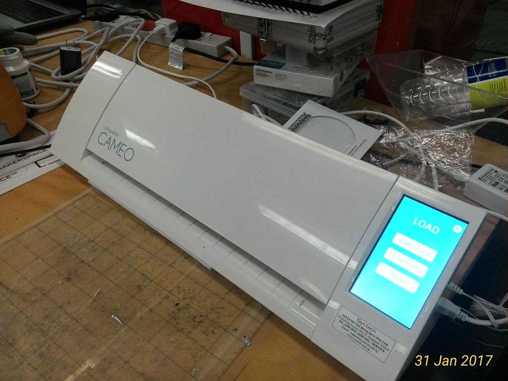
The vinyl cutter I used was the desktop Cameo Silhouette as shown in Figure 1.
I kick started by learning from two videos in youtube on how to use the Cameo Silhouette and, How to trace picture.
I leant that the process involved are as describe in Figure 2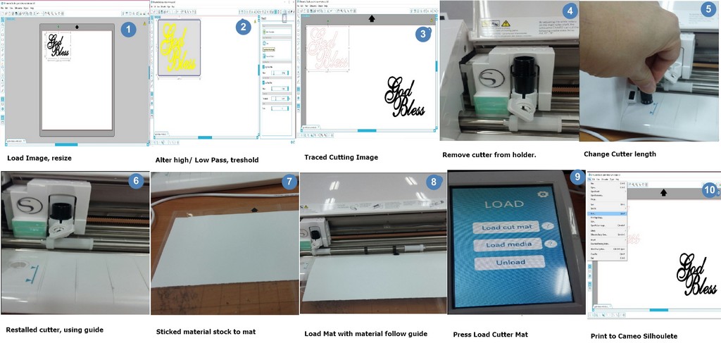
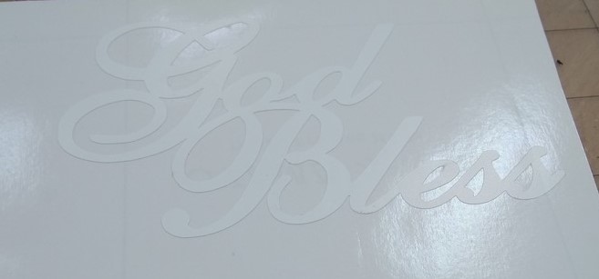
Upon creation of the vinyl sticker, I safe keep till week 8 then finally thinking of pasting it on my laptop. I used the tranfer tape as shown below to shift the vinyl sticker as shown:
![]()
Laser cutting attempts (without considering on Kerf).
I got a bit over confidence at time. Which made me jumped straight into cutting out my protype of my laptop stand using the dxf files I exported from my 3D CAD drawing in Fusion 360. In my first attempt which I made a silly mistake, forgetting on the material thickness parameter which was set to be in inches and my physical material thickness is only, t~ 4.65mm (in metric unit). I first cut out the two legs and the supports and two supports for the legs but found that those are not able to be assembeld. All the materials were recycled and reused from the left over by our Students.
On the second attempt, once again I only cut out the legs and the supports of my laptop stand without the top. (With actual physical thickness of the same stock of plywood measured with a vernier Caliper- t=4.65mm. But again the physical fitting is still very loose. After visually examined the slots created without really taking any measurement, I proceed for my 3rd attempt to cut out the entire laptop stand with the material thickness set to t=4.45mm. By luck the entire structure fitter perfectly tight. The three attempts were done without the consideration and knowledge of kerf or whatsoever but solely with trial and error and reduced the drawing thickness of the plywood parametrically by about 0.2mm.
It is also through repeat trial and error that with our laser machine to materials and thickness cutting through parameters/setting characterization process. Through the process we have established a series of cut through proof laser cutter parameters for various thickness of plywood and cardboard (most commonly use materials for our diploma courses). In which the basic settings/parameters to cut through "5mm" thick plywood are as follow(Power=40%, Speed=3%, PPI=200 pulse per second for z = thickness = t = 5mm). Personnally, I would prefer to reduce the laser power to 35%, varied my speed between 3% to 4% while setting the PPI= 400PPS. Somehow with this setting on the Universal VLS laser machine the output appear to be with less carbon soot as compare to PPI of 200pps.
With that in mind, I proceed to read up further to understand more about Press fit construction tips and on what is kerf.
Laser Cutter Assignment
For this weeks's assignments, I used our Universal VLS 6.60 60W Laser machine, to cut on t=4.86mm plywood. Prior to this, normally we would take the thickness as t=5mm and just used the "cut-proof" laser cut parameters file as per Figure 5.
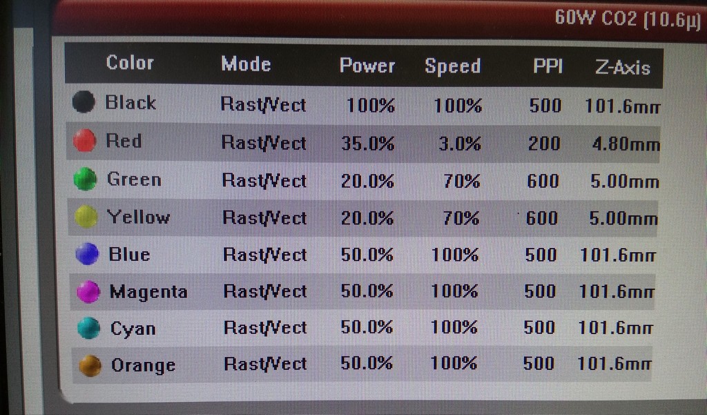
No different for this study of kerf, I began with the cutting parameter file for 5mm thick plywood but reduced the plywood thickness to z= 4.8mm, power to 35% instead of 40%, varied the speed to 4% instead of 3% and keeping the PPI at 200pps.
With that it had produced the cut out of the first square as show in figure 6:
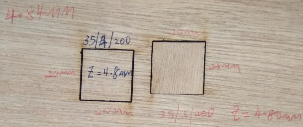
To my surprise it didn't cut through. I suspected that the speed might be too fast so I reduce it to 3%. The rest of the parameters remain. With this setting it resulted in a "just cut through" square (second square as in Figure 6) and I am taking measurements based on this square to determine the Kerf value.
Similarly, I had repeated the cutting using some left over plywood of t=2.42mm and took measurement using a digital vernier caliper. With cutting parameters further refined to "optimum" as show in figure 7:
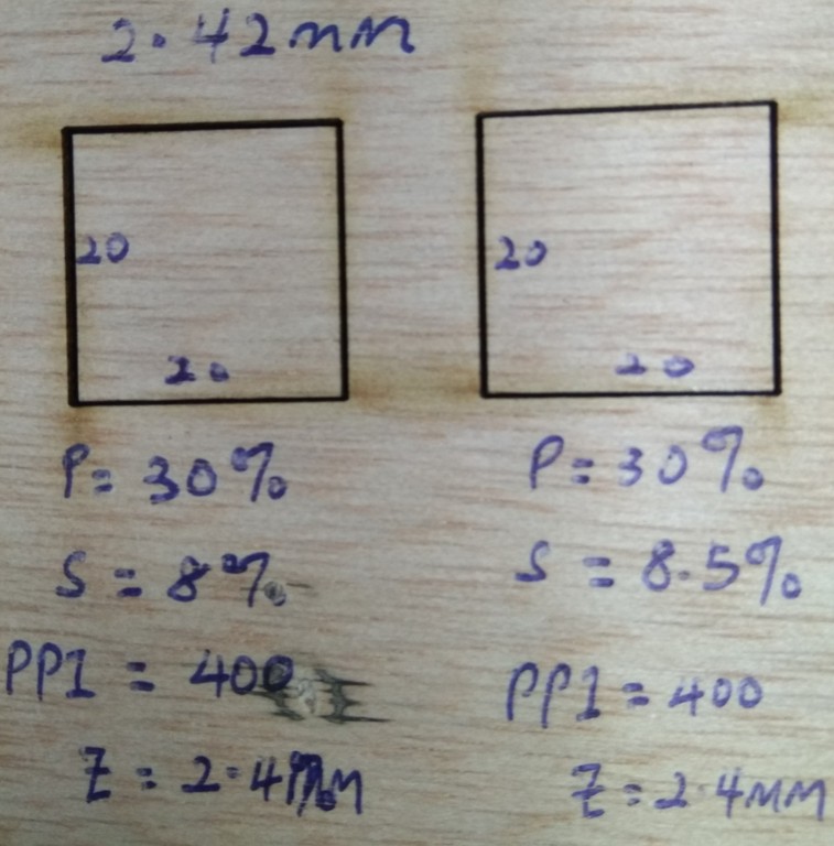
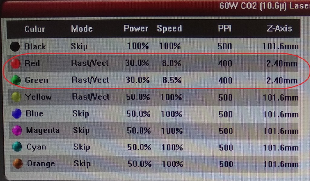
For this t=2.42mm plywood, our laser machine can only take in the thickness as 2.4mm. With this I set the cutting parameters based on our in house cut proof parameters and refined to the two setting as shown in figure 8.
So after talking so much, what is kerf after all?
Kerf is the amount of material that is being removed by a cutting process along the cutting path. In simple term the relationship of the drawing sizes to kerf can be understand from Ponoko explaination on this.
We tried on plywood and made 4 sided female connectors of each 0.1mm difference to see which size fits the best. We started with plywood of thickness=2.47 mm with cut out drawing as 20mm (loose) and also cutout drawing of 19mm (can't go in). From this we deduced that for press fit to happen it must be at the cutout drawing size of between 20mm to 19mm. From there, we slowly worked it's way down to 19.6mm; where there was some interference started to be felt. We did measured the tab and cutout hole for plywood of t=2.47mm and plywood of t=4.86mm thick. For demonstration, I would just show the picture using plywood of thickness, t=2.47mm as illustrated in Figure 9.
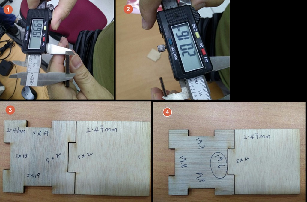
I measured the values of the outside edges of the square and the inner edges of the resulting square. The difference in the 2 values, divided by 2, gives the kerf for t=4.84 mm and t=2.42mm thick plywood are as follow:
| Laser Setting | Square (inside) | Hole (outside) |
|---|---|---|
| S/PWR/PPI/Z | Win, Lin | Wout, Lout |
| 3/35/400/4.8mm | 19.81,19.74 | 20.15,20.12 |
| 8.5/30/400/2.4mm | 19.94,19.85 | 20.16,20.05 |
From the values above, the worse case senario kerf can be calculated:
- 4.8mm plywood (SPD/POW/FREQ 3/35/400): (20.15mm - 19.74mm)/2 = 0.21mm
- 2.4mm plywood (SPD/POW/FREQ 8.5/30/400): (20.16mm - 19.85mm)/2 = 0.16mm
The above findings indicate that both the material thickness and cutting parameters play a part in the amount of material being burnt away for the same plywood type of different thickness - kerf. The thicker the material the higher is the Kerf. This make sense, as the thicker the material, the higher the power required to cut through, the slower the speed of cutting, the greated pulse of laser (intensity) is required.
Once the kerf is determined, I proceeded to create a standard box shape for laser cutting cut file using the Inkscape's tabbed box maker extension for the t=4.86mm plywood.
Note: One important point to note - Inkscape uses 90 ppi for jpg and png files, whereas CorelDraw uses 96 ppi. When exchanging files between the 2 platforms, you need to scale up or down by that ratio, i.e. when importing Inkscape files in CorelDraw, use a scale factor of 96/90 = 1.067.

The cutting file generated can be found at Section Download Week 3 work files. I didnot cut out using the file generated, as I found that was running out of plywood of the same stock.
Press-fit Box
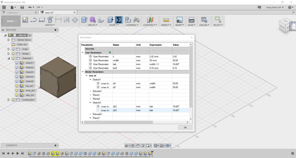
I decided to use another approach to create my press-fit-box with plywood of t=2.42mm incorporated with this new found kerf value. I constructed my 3D cube in Autodesk Fusion 360 parametrically with parameters like t=thickness, width=lenght=height of cube= 50mm, size of tab= width/3. The 3D Cad drawing is as shown in Figure 11->export the parts drawing into DXF files (top.dxf,front.dxf, side.dxf).
 The DXF cutting files generated are found in the "Download Week 3 work files".
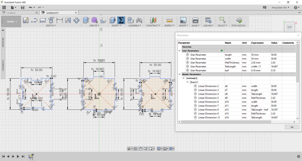
Oops! I got a bit confused how to incorporate this Kerf into my existing 3D CAD drawing to parametrize the output for cutting. So rather than using the 3D CAD file, I redrew the 2D skecthes in Fusion 360 as shown in figure 12.
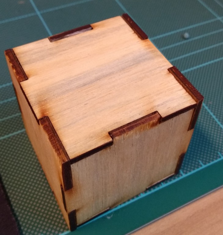
The result is Press Fit Box/Cube of 50mmx 50mm x 50mm as illustrated in figure 13.
Press fit space ship
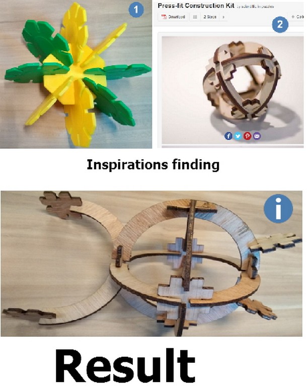
When my wife saw me referred to my kid's toy to find idea for fun making press fit construction kit/toy, she jokingly asked whether can make some toy out of it.
Based on the press fit design from Instructables I had decided to construct a imaginary press-fit space ship for my boy to have some fun. Valla! The "Result" is as shown in figure 14.
Reflection
Only at 3rd week of the course even on the topic that most of us are quite farmiliar with - Laser cutter; I already began to feel that there was not enough time do everything. This was especially true that we are still dealing with our daily routine works, dealing with students rushing for projects, closing of financial year account, various improvement work meetings, management meetings, employment performance meeting and so on.
When in a rush, we still got to deal with various issue, like non familiar/compatible software version for various laser cutters Epilogue onlu run with Corel Draw, Universal with Illustrators and AutoCAD.
At Singapore, everything is so competitive and moving at a fast speed. With more than 100 students rushing to use laser cutter at every semester, we can't really let students work on things like kerf and finding of "optima" cutting parameter- aka charasterisation test of each machine. Neither can we let students use a software that is not being thought in their diploma study. That is why on top of coreldraw (not in our Rapid Prototyping studio. As non of our diploma course teaches this software), we have worked with the course person in charge to identify and chosen two software that are being thought in our School (Which are AutoCAD and Illustrator). To further speed thing up, only one pass to cut through the workpiece for various material is allowed. As such the study of Kerf become critical and new to us to determine the correct sizing for press fit design.
With current mad rush- we really don't have much time to think through how this study of Kerf can be implemented in our syllabus. Very importantly improving on the ways our students plan and consider their project work to construct of this press-fit model in the future. Hopefully, we will have enough time for next week... and also my boy will be impressed by my press fit space ship. :)
Download Week 3 work files
- God Bless Vinyl Sticker
- Inkscape2Box.svg
- Parametric press-fit box in Fusion360
- Parametric press-fit box DXF
- Press-fit spaceship construction kit (ai).
References
- Press-Fit Construction Tips
- CNC Panel Joinery Notebook - different types of joints are introduced.
- Inkscape how to make a pressfit design - a step-by-step guide using Inkscape.
- A Quick Guide to Inkscape - how to make clone objects using Inkscape.
- Understanding the "kerf" of the laser
- How to Adjust for Wood Thickness and Kerf on a Laser Cutter at Techshop