WEEK15-NETWORKING AND COMMUNICATIONS
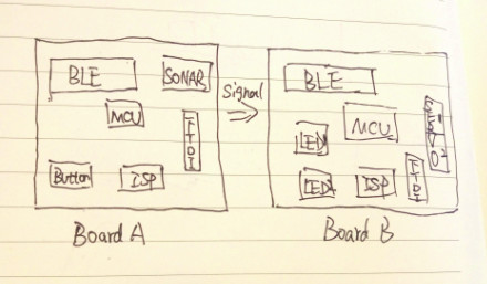
My final project is degining a gravity car, the turing is controlled by the distance between the weight and the plate of car. And all the messages like the distance, circles the car has gone, the efficiency of tranfering from gravity to engrgy of motion, etc can send to phone. and all control like start, stop can execute by phone. This weel two boards were designed and build. One is the input devices with a blue tooth, the other is excuting devices and a blue tooth. They were showed in the fllowing figure.
Part 1 PCB Board Design
-
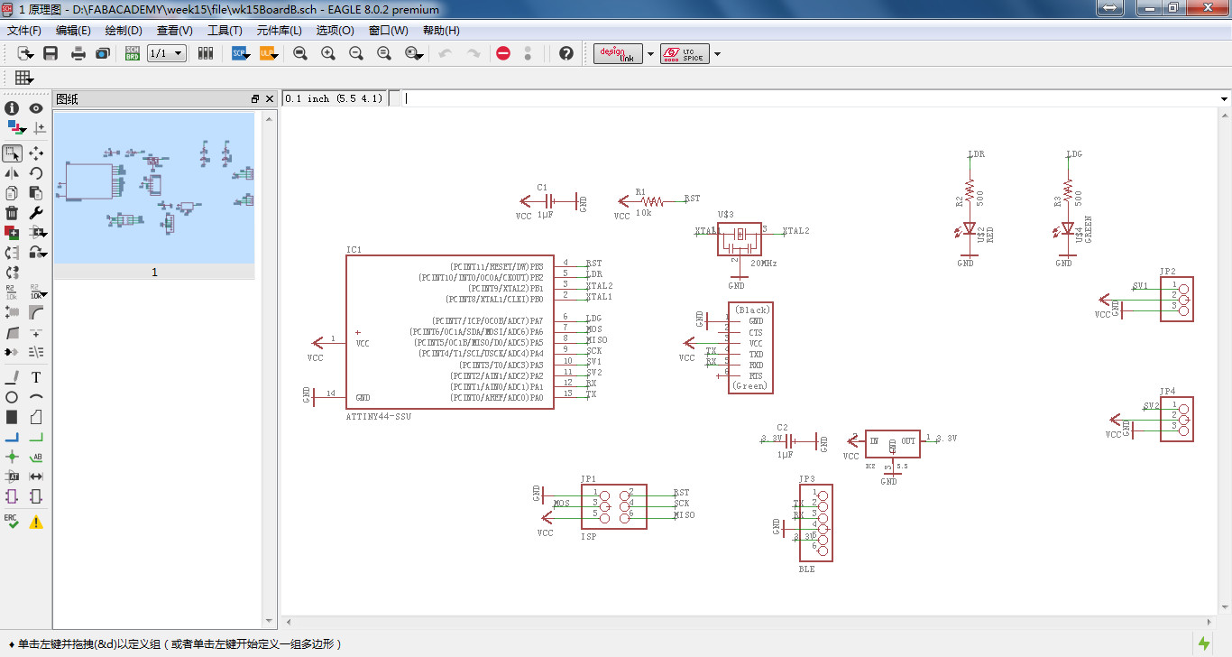
1.Open egale and new project, open a schematic diagram. The components need as follow:
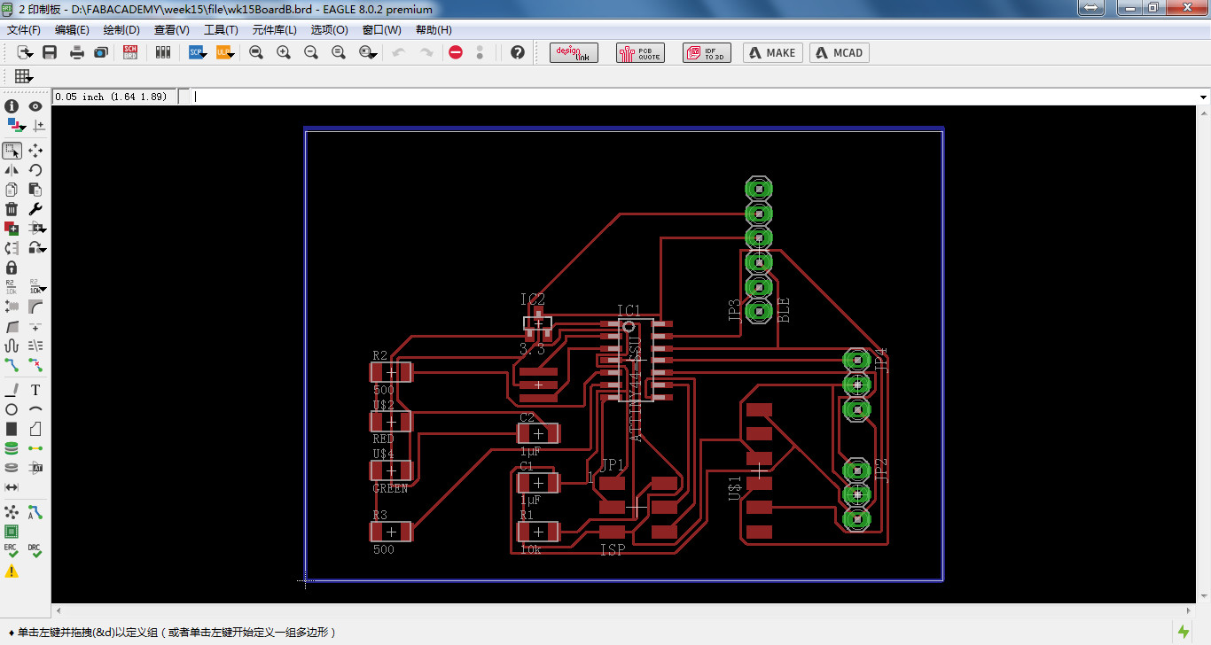
MCU attiny 44 X1 BLE CC2541 X1 Servo X2 LED red X1 LED green X1 FTDI X1 ISP 2X3pin X1 Capacitor for MCU X1 Capacitor for BLE X1 Resonator for MCU X1 Resistor for ISP X1 Resistor for led X2 Regulartor for BLE X1 - 2.Connect the components and generate the print board. Set design rules and click on autoroutor.
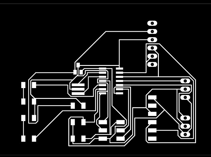
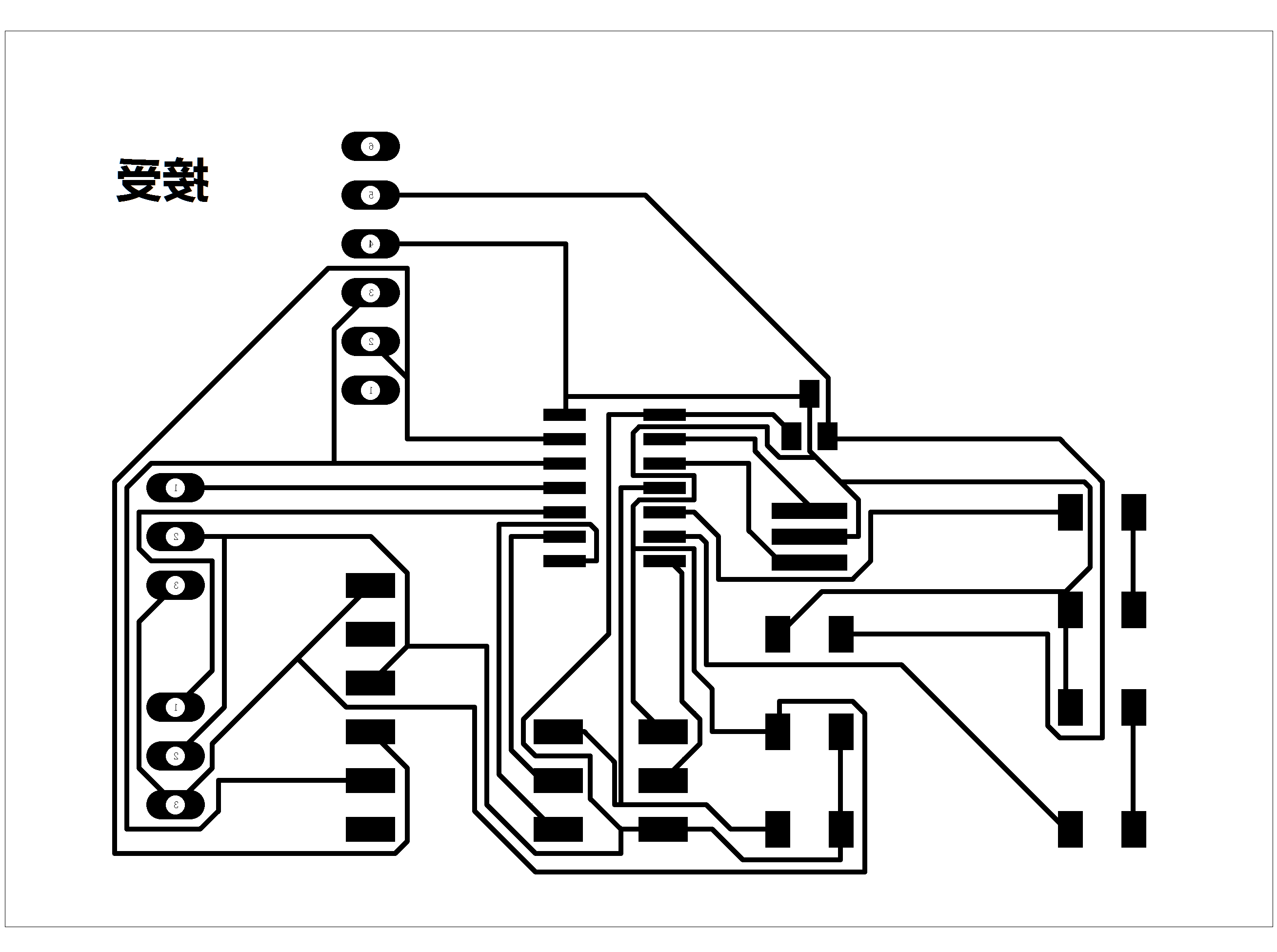
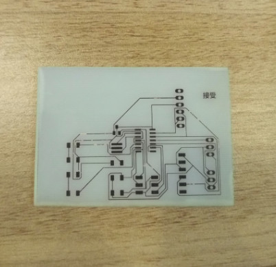
- 3.Export an png of PCB. I've never use an noraml method like etch a pcb board, I will try this week, the method is a little different with mill, the picuture was print on a smooth paper, and a thermal tranfer printer will print the picture on the pcb board. So the picure should be color invert and mirrored.
-
Part 2 Create the board
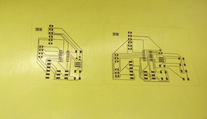
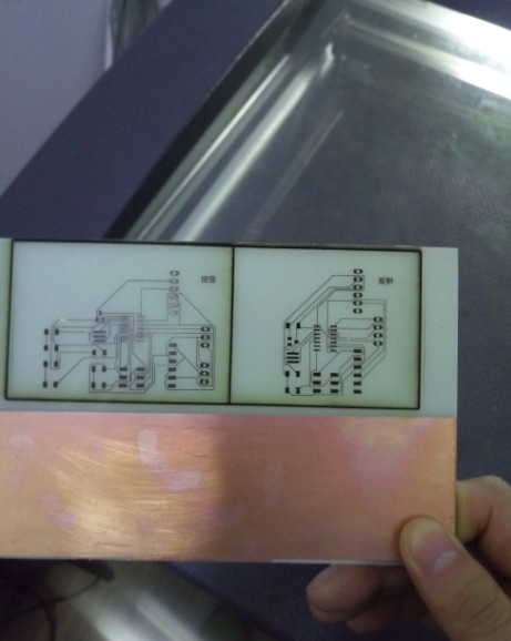
- 1. Print the pcb picture on a smooth paper.
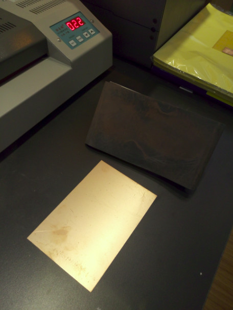
- 2. Polish the Cu clad board with sandpaper, for CuO should be removed.
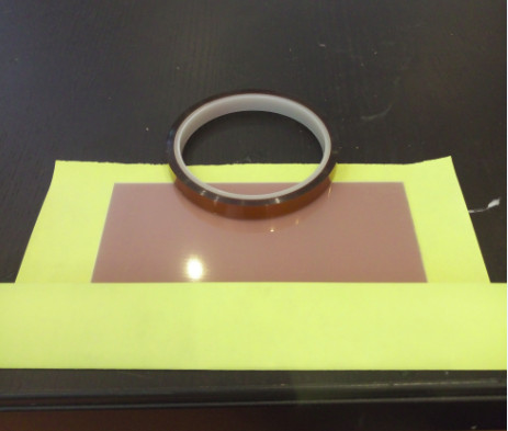
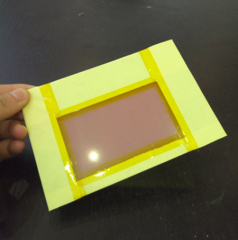
- 3. Put the smooth paper on the board the picture should tight stick to the board. A kapton tape was used for fixing.
- 4. The smooth paper was totally wrap the board.
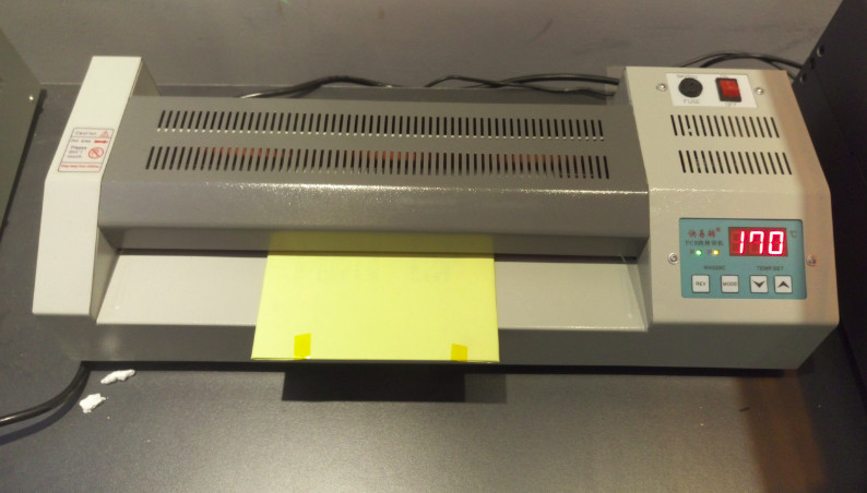
- 5. Open the thermal print transfer machine, set a working temperature as 170 ℃. Put the board into the machine after the P lamp was on.
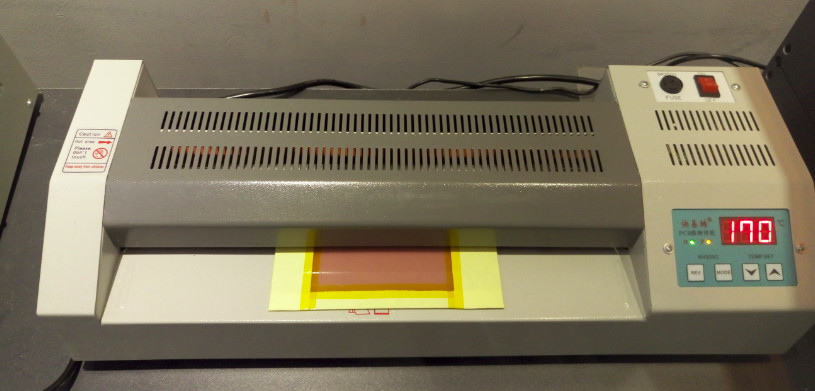
- 6. Turn around the board and put it into the machine these two process should be done for 4 times.
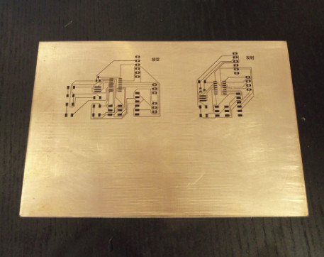
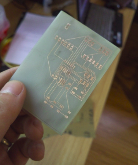
- 7. The picture was tranfered to the board, it is very precisely.
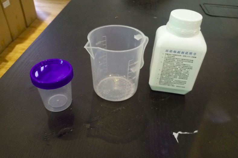
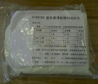
- 8. The etch is an environmentally friendly material. It is nontoxic, no smell, high security, reused for long time.
- 9. Cupric ion in the liquid after etched, the cupric was harmful to the environment. An alkaline material can make the liquid to solid for the etch is weakly acidic.
- 10. Put the board into the etch tank. Wait about 10 mins the board will be precisely produced.
- 11. I want to cut the pcb to a small size, but it dont work well. I cut it by knife at last.
- 12. The borad was build, it is beautiful.
- 1. Polish the board before soldering because the graphite carbon must remvoed.
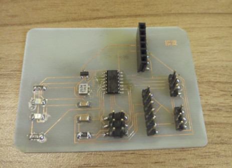
- 2. Refer to the drawing and soldering.
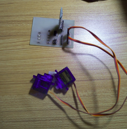
- 3. Insert the servo motors and blue tooth module into the board.
Part 3 Soldering
Part 4 Programming and testing
For I have finished my final electronic board, so I programmed it in the final board, and I send the distance to phone.
#define TrigPin A4
#define EchoPin A5

float getDistance(void)
{
  float distance;
// 产生一个10us的高脉冲去触发TrigPin
  digitalWrite(TrigPin, LOW);
  delayMicroseconds(2);
  digitalWrite(TrigPin, HIGH);
  delayMicroseconds(10);
  digitalWrite(TrigPin, LOW);
// 检测脉冲宽度,并计算出距离
  distance = pulseIn(EchoPin, HIGH) / 58.00;
  return distance;
}

void setup()
{
  // 初始化串口通信及连接SR04的引脚
  Serial.begin(9600);
  pinMode(TrigPin, OUTPUT);
  pinMode(EchoPin, INPUT);
}

float dis = 0;
void loop()
{
  dis = getDistance() * 10; //mm
  Serial.println(dis);
  delay(300);
}