WEEK08-EMBEDED PROGRAMMING
Part 1 Programmed by c language
- 1. Build a .c file.
- Find the files which have used on week06. Rename the .c file as ledon.
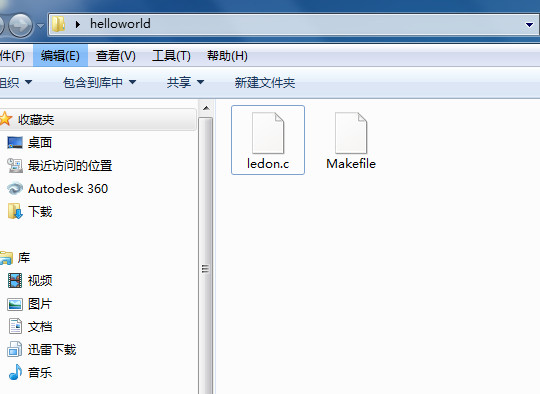
- 2. Edit Makefile.
- Open the makefile with brackets, and edit the name of project, named it as ledon.
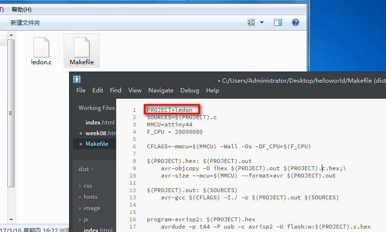
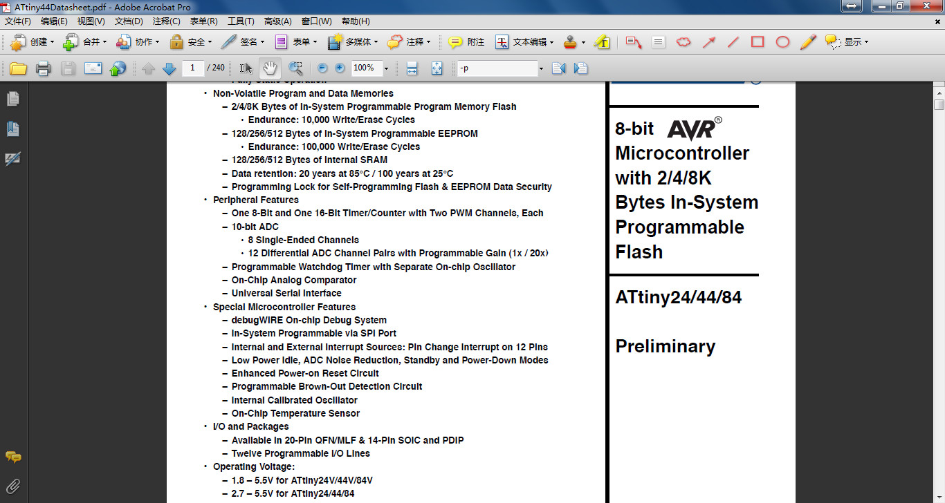
- Read attiny44 datasheet and edit the makefile to control board.
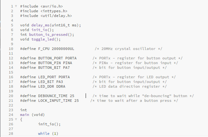
- 3. Program in .c file.
- Read the C programming language and program.
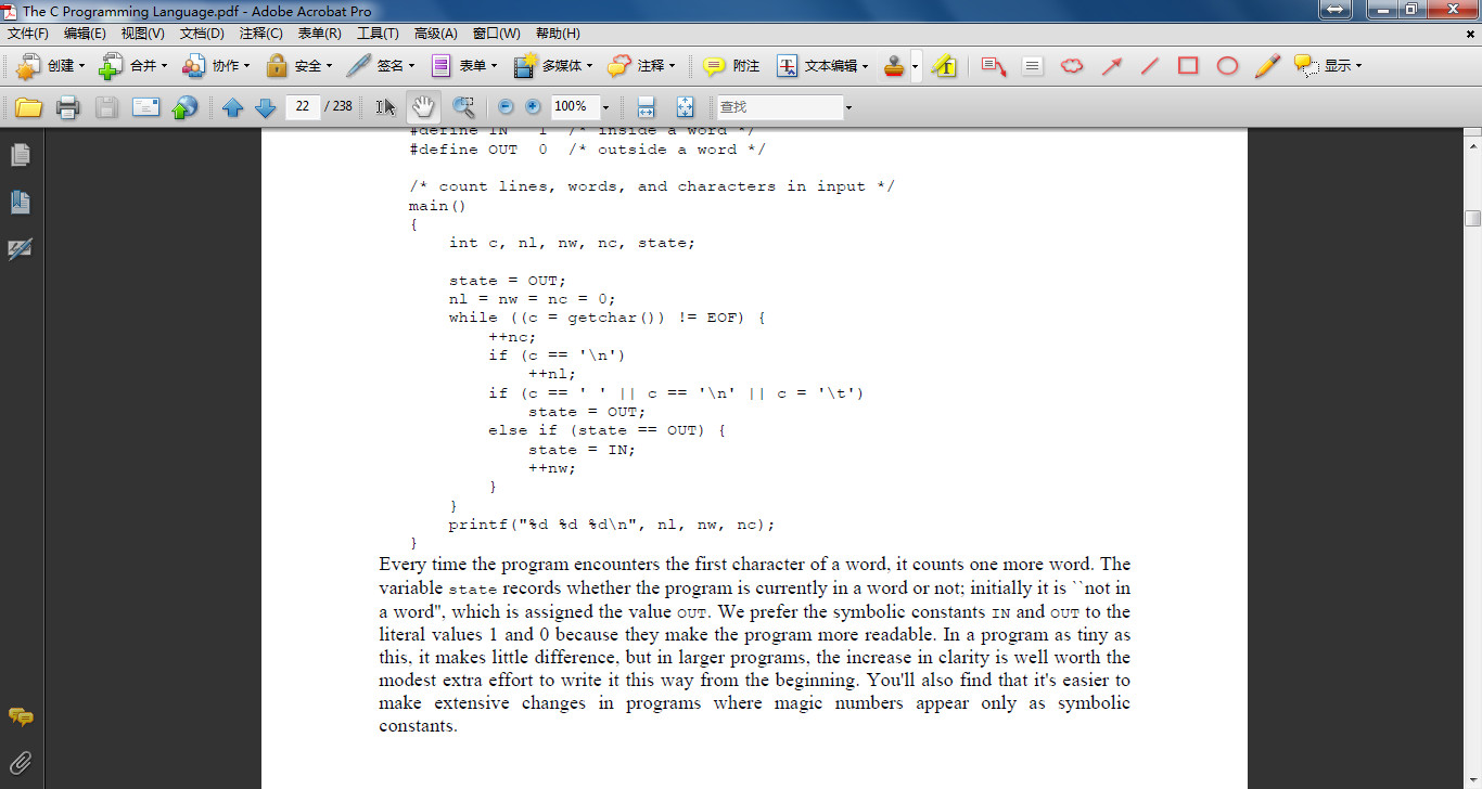
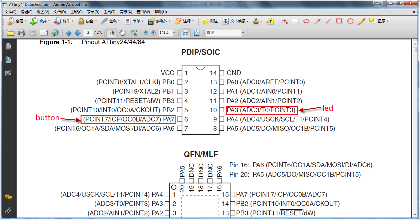
- Find the pin for button and led, the button is PA7 and LED is PA3.
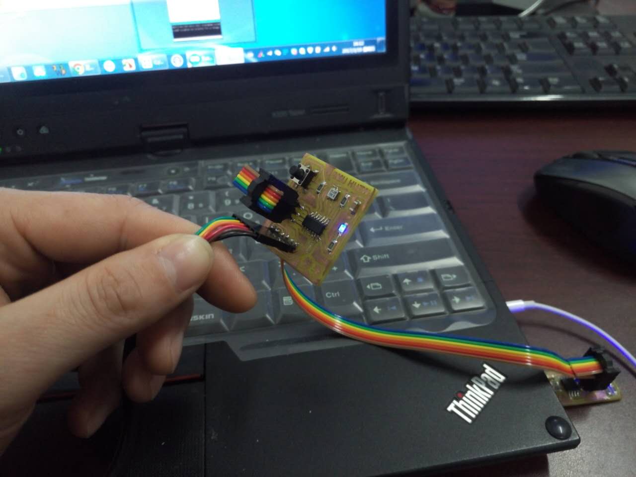
- 4. Upload to board.
- Open GIT BASH and cd to the folder. Ender make and the .hex and .out file were created. and then make program-usbtiny and make program-usbtiny-fuses, then the code upload to board.
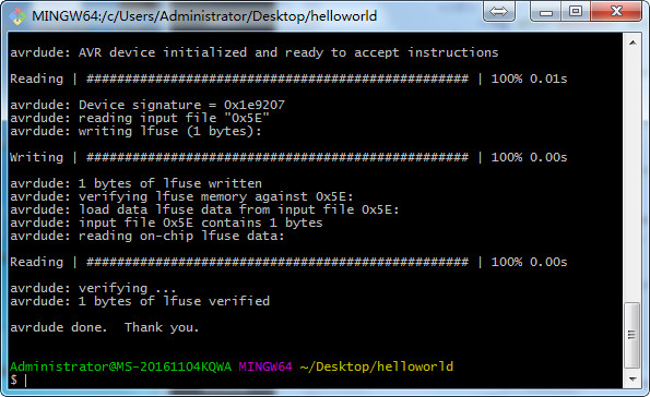
- The led is on.
Part 2 Programmed by Aruduino
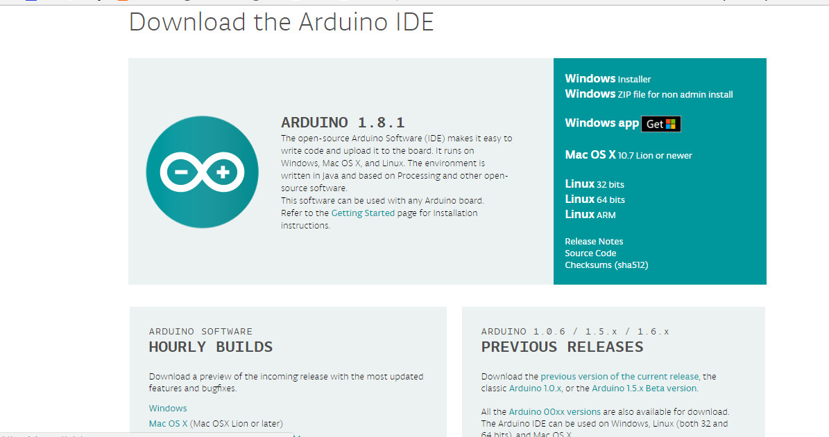
- 1. Download arduino software.
- Program by arduino is easier. Download arduino first, and setup.
- 2. Set arduino for board.
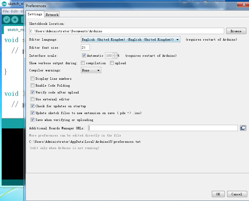
- Open the software and set for attiny44, for there is no borad attiny44 in tools-board. Open file-preferences.
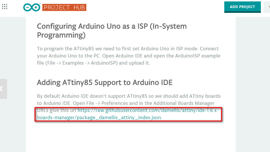
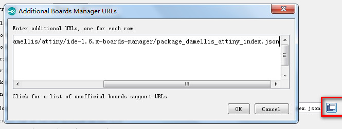
- Add a URLs for additional boards manager. The urls was found. https://raw.githubusercontent.com/damellis/attiny/ide-1.6.x-boards-manager/package_damellis_attiny_index.json.
- Copy the urls and click on OK.
- Open tools-board-board manager, it will refreshing, find attiny after refresh down.
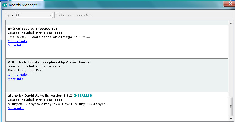
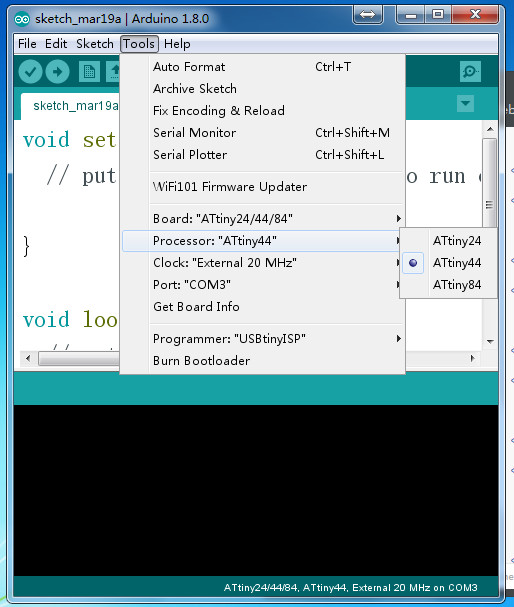
- Choose board as ATtiny 24/44/84, processor as ATtiny44, Clock as External 20MHz, port as COM3, programmer as USBtinyISP.
- 3. Programed by arduino for test.
- Open examples and it is convenient to set a program of board.
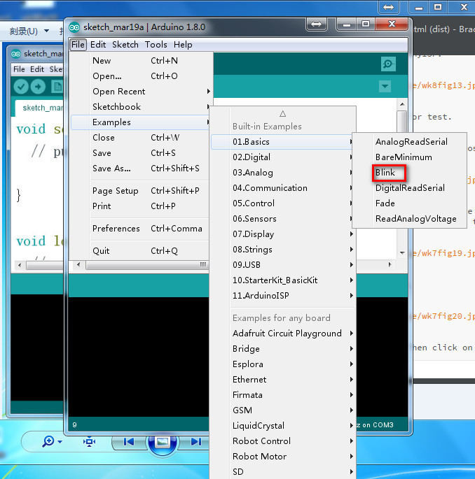
- It's a simple for controlling the led blink. Click on upload.
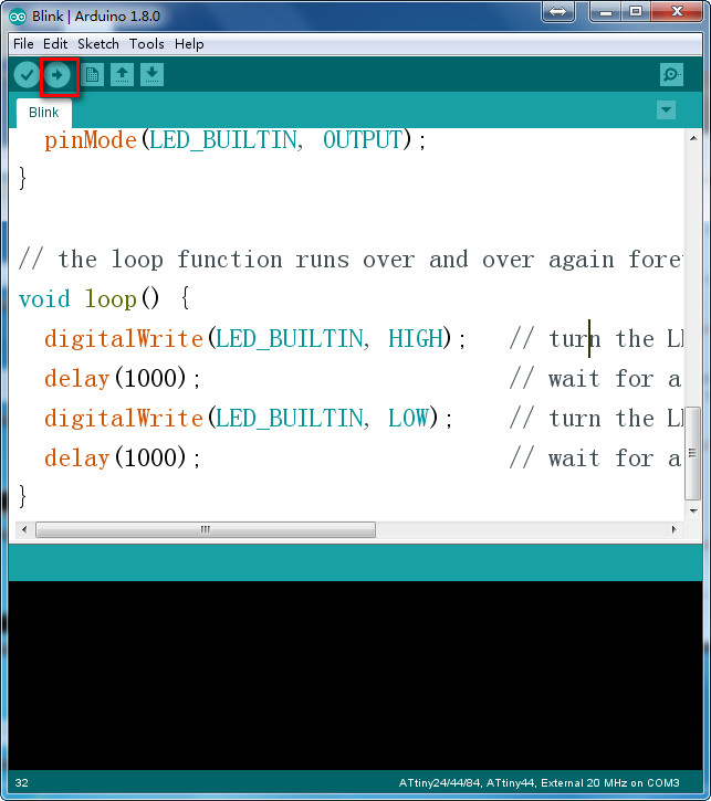
- Wait a second the led will blink after the uploading.
- Open the button example and use button to control the led.
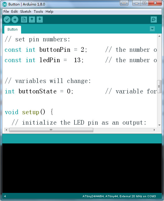
- The pins of attiny44 and arduino are different so find the difference and change it.
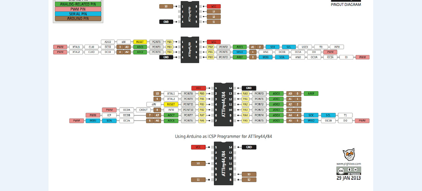
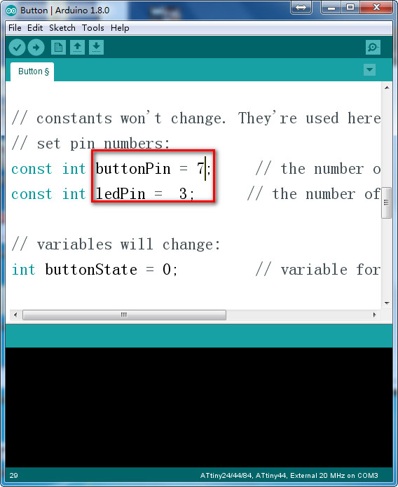
- I use pin6 for button and pin 10 for led, compare to the picture the buttonpin should be 7 and ledpin should be 3.
- 4. Upload to the board.
- Click on upload and then the led will be off and it will be on after press the button.
- 5. Make the board do sth by arduino.
- Make a breath led, the brightness increase/decrease as time. AnalogWrite can control 0~255, and then control the led brightness.
const int buttonpin=7;
const int ledpin=3;
void setup() {
pinMode(ledpin, OUTPUT);
pinMode(buttonpin, INPUT);
}
void loop() {
for (int i=0; i<=255;i++)
{
 analogWrite(3,i);
 delay(8);
  }
 for(int i=255;i>=0;i--)
 {
  analogWrite(3,i);
  delay(8);
  }
 delay(200);
}
- Upload to board, but it doesn't work.
- The brightness was controlled by a signal that can change, look at the pin of ATtiny, pin 10 doesn't have the function of PWM.
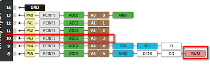
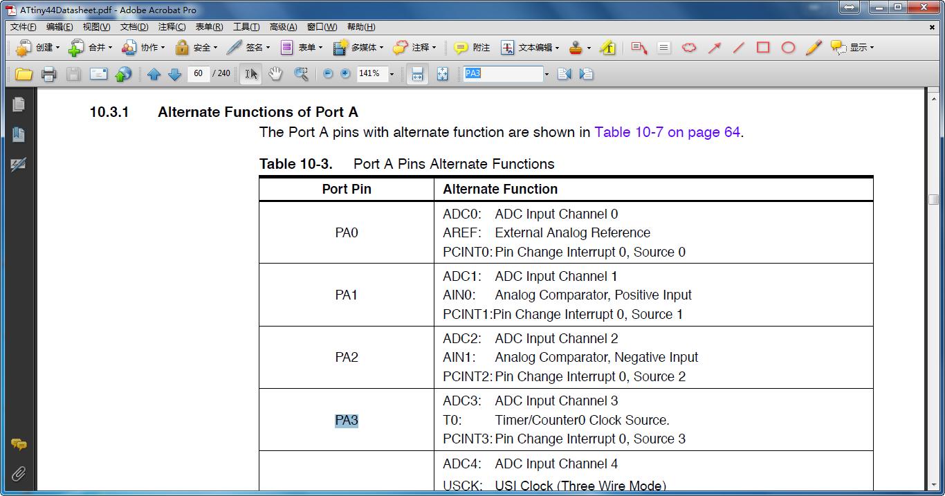
Read the attiny 44 datasheet, the pin I have used for led has three functions.
• ADC3: Analog to Digital Converter, Channel 3.
• T0: Timer/Counter0 counter source.
• PCINT3: Pin Change Interrupt source 3. The PA3 pin can serve as an external interrupt source for pin change interrupt 0.
- Designed another function, the led was off when button wasn't pressed, one press the led blink slowly, two press the led blink quickly, then press the button led was off.
const int buttonpin = 7;
const int ledpin = 3;
int flag = 0;
void setup() {
  pinMode(buttonpin, INPUT);
  pinMode(ledpin, OUTPUT);
}
void loop() {
  if (digitalRead(buttonpin) == LOW)
  {
    while (digitalRead(buttonpin) == LOW);
    flag++;
    if (flag > 3)
      flag = 0;
  }
  if (flag == 0)
  {
    digitalWrite(ledpin, LOW);
  }
  if (flag == 1)
  {
    digitalWrite(ledpin, HIGH);
    delay(100);
    digitalWrite(ledpin, LOW);
    delay(100);
  }
  if (flag == 2)
  {
    digitalWrite(ledpin, HIGH);
    delay(10);
    digitalWrite(ledpin, LOW);
    delay(10);
  }
}
- Upload to the board, it works.