WEEK06-ELECTRONICS DESIGN
Part 1 Design
- 1. Schematic design.
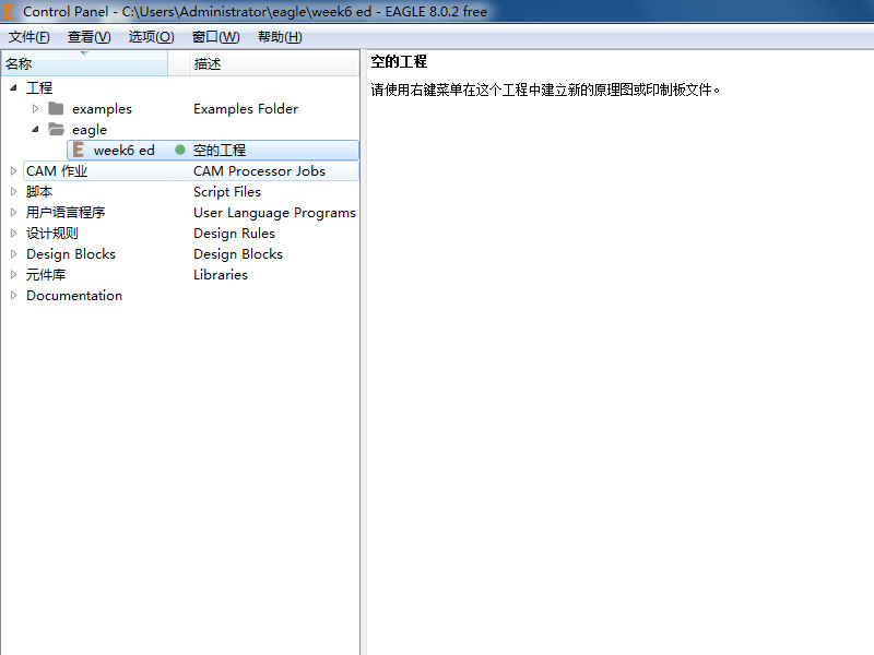
- The assignment of this week is design a PCB and make it. Use software EAGLE to design. EAGLE is a convenient electronic design software. We need a chip as the brain of unit, ISP connect to programmer, FTDI for powering, and some components like resistor capacitor for protect or stable, and some other I/O elements like led, button. Download the software EAGLE and setup, open it and click on new project.
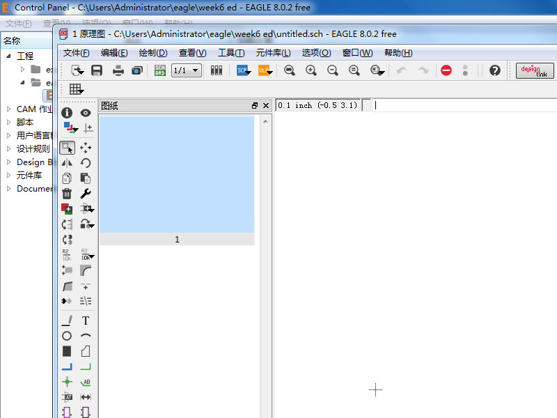
- Click on new schematic.
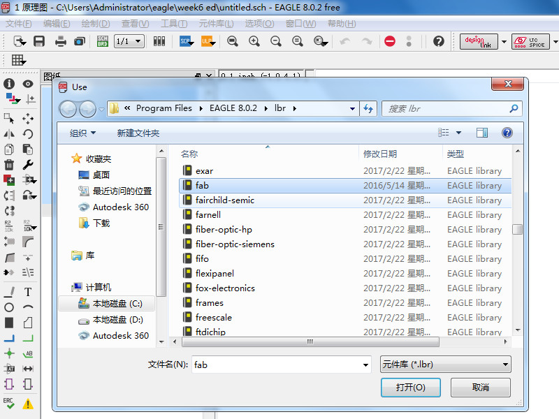
- Find the library name fab, there are all of components we can use in the lab.
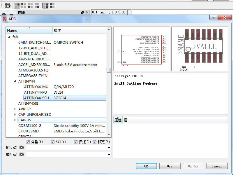
- Add chip we use ATTINY44, there are three in the library click on ATTINY44-SSU and click on use.
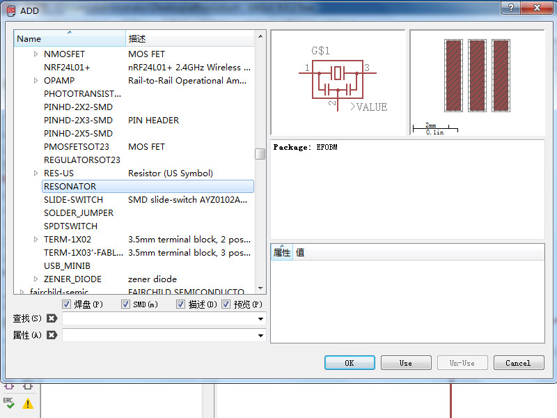
- Add a resonator it contain a crystal and two capacitor, it can regulate voltage.
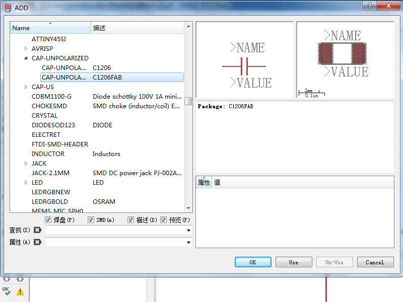
- Add a capacitor. There are two kinds choose C1206FAB.
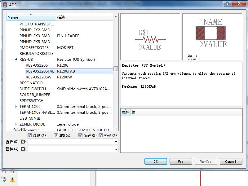
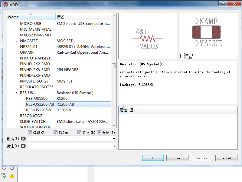
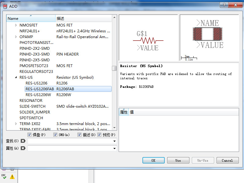
- Add a resistor. Choose R1206FAB.
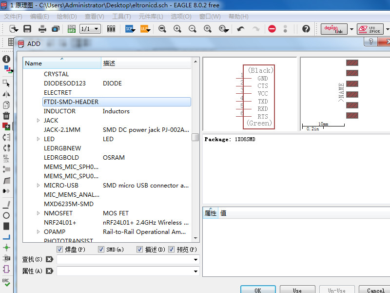
- Add FTDI HEADER.
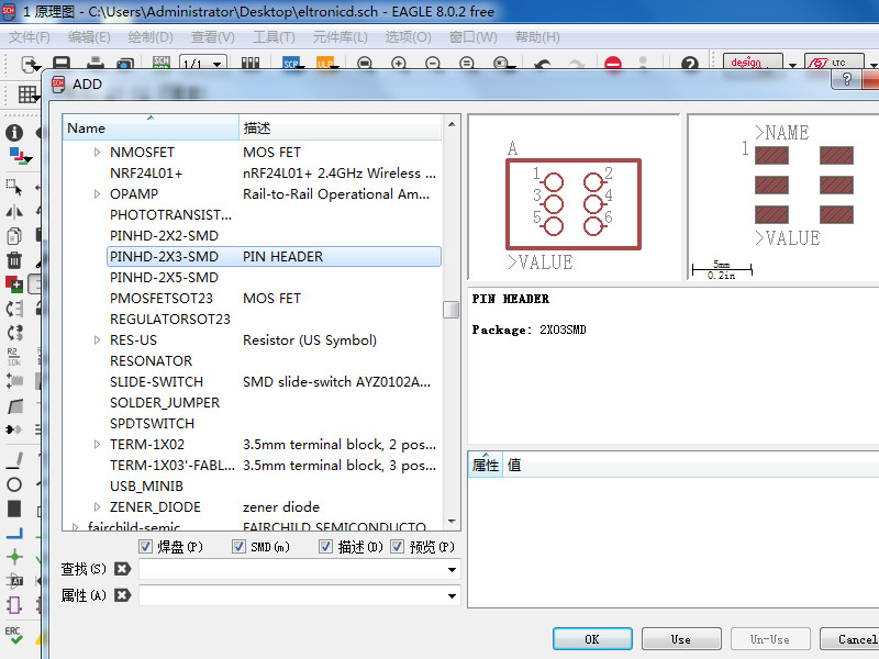
- Add a pinhead choose PINHD-2X3-SMD.
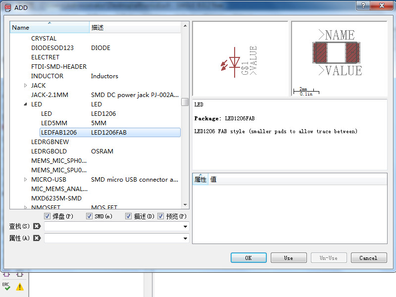
- Add a led choose LED1206FAB.
- Add a resistor for led also choose R1206FAB.
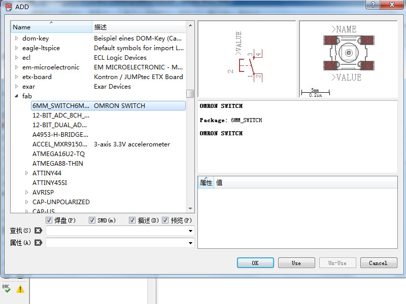
- Add a 6mm switch, actual it is a button.
- Add a resistor for switch.
- Search GND and choose supply GND.
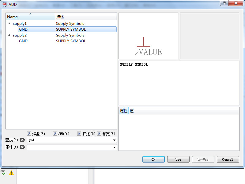
- Add where you need and right-click can change the direction of GND.
- Search VCC and choose supply VCC.
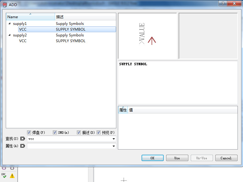
- Add where you need and right-click can change the direction of VCC.
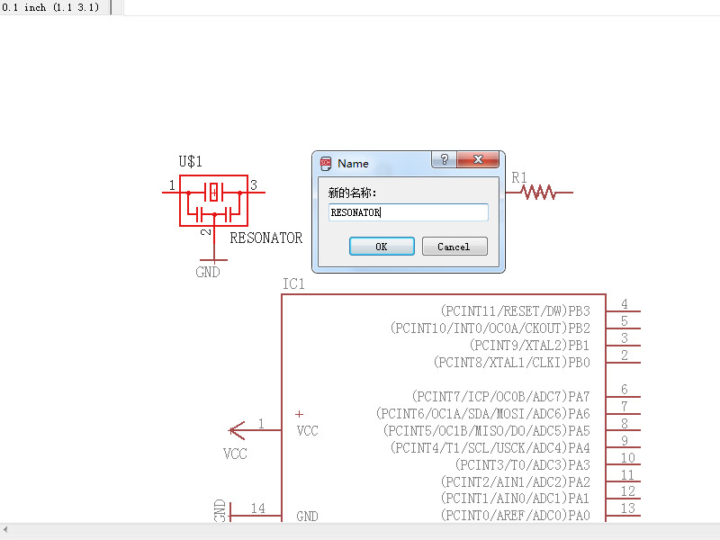
- Rename the components. Click on rename and click on the component and enter a new name.
- Set the value of components.
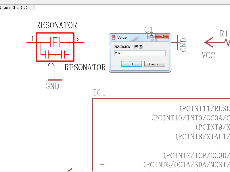
- Resonator is 20MHz, capacitor is 1 μF, resistor1 is 10k, resistor2 is 500, resistor3 is 10k, LED is blue.
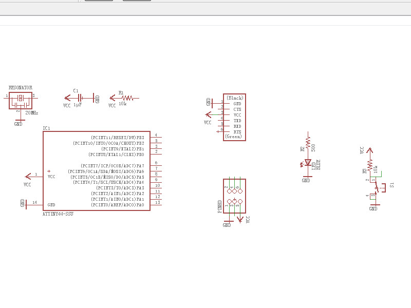
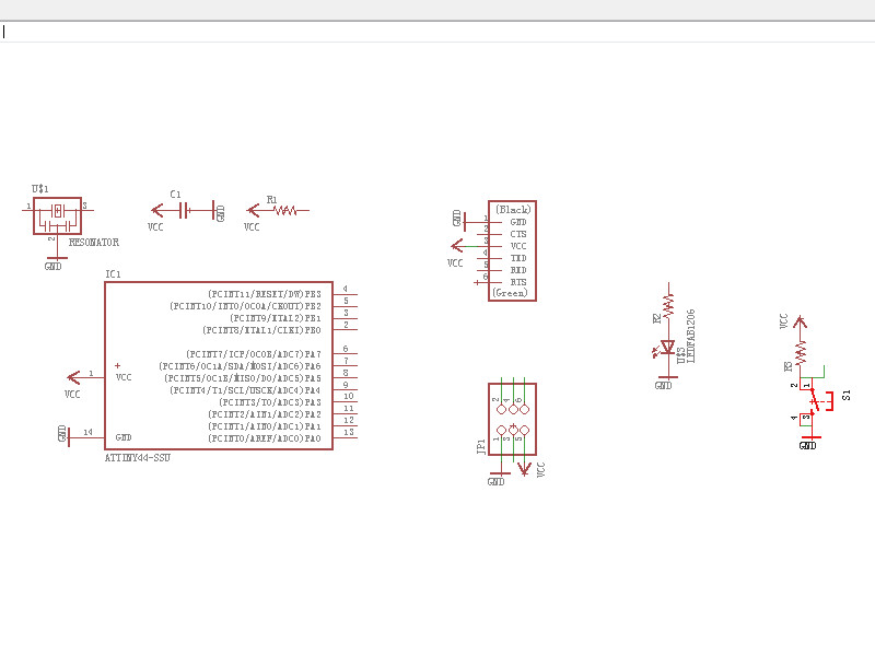
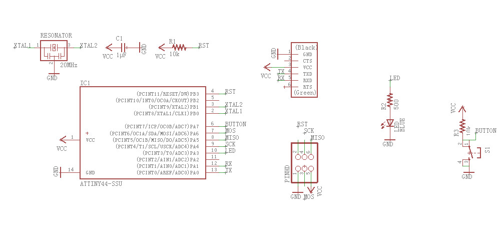
- Add wire on the pin and then add label for pin.
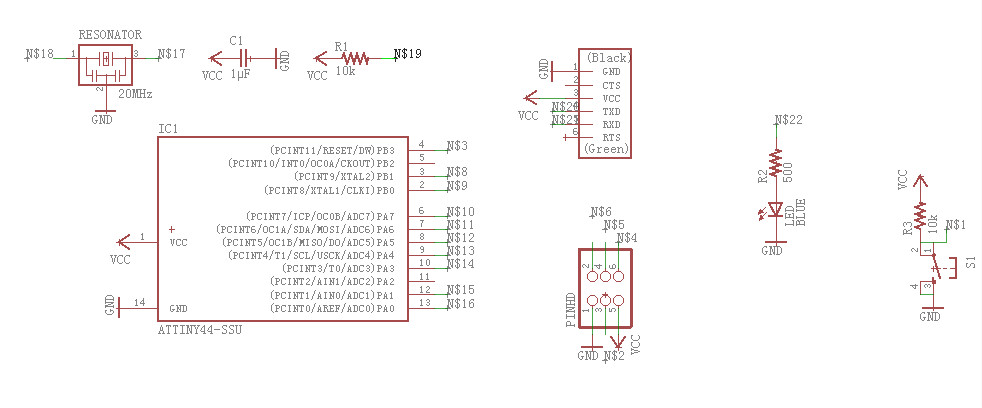
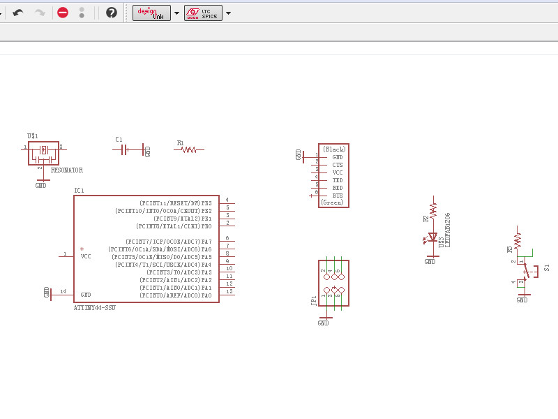
- Rename the label and make the same label connect. The schematic was completed.
- 2. BRD desgin.
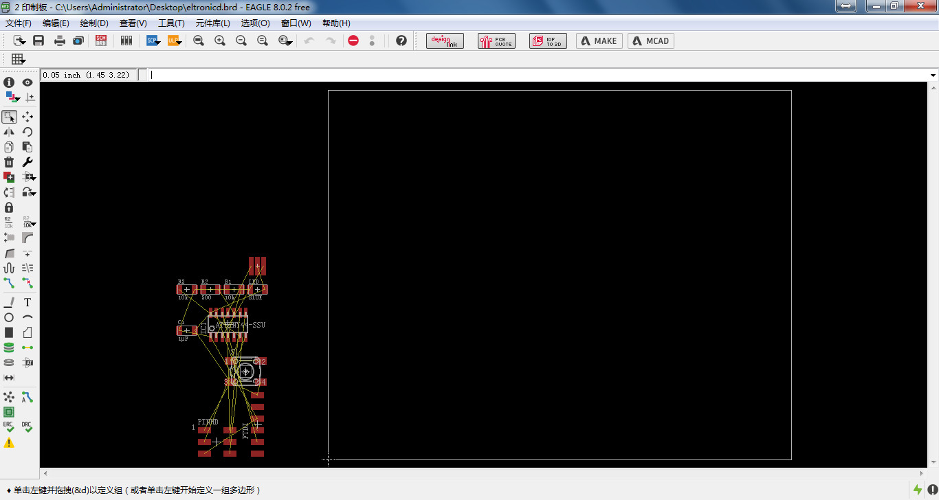
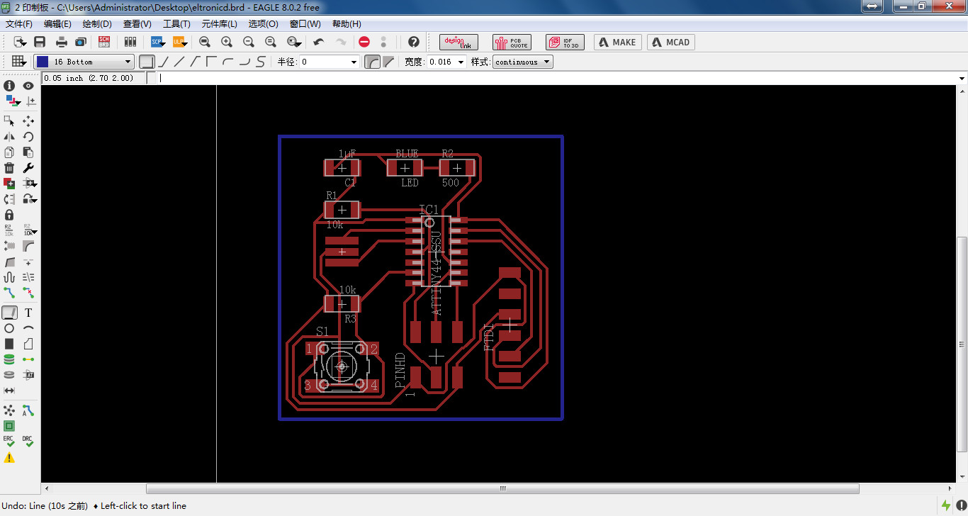
- Click on SCHBRD icon it wil ask you if you want to build a brd, click on yes.
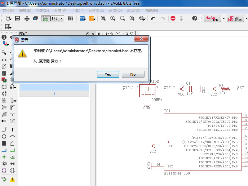
- The BRD was build, but it should be adjust.
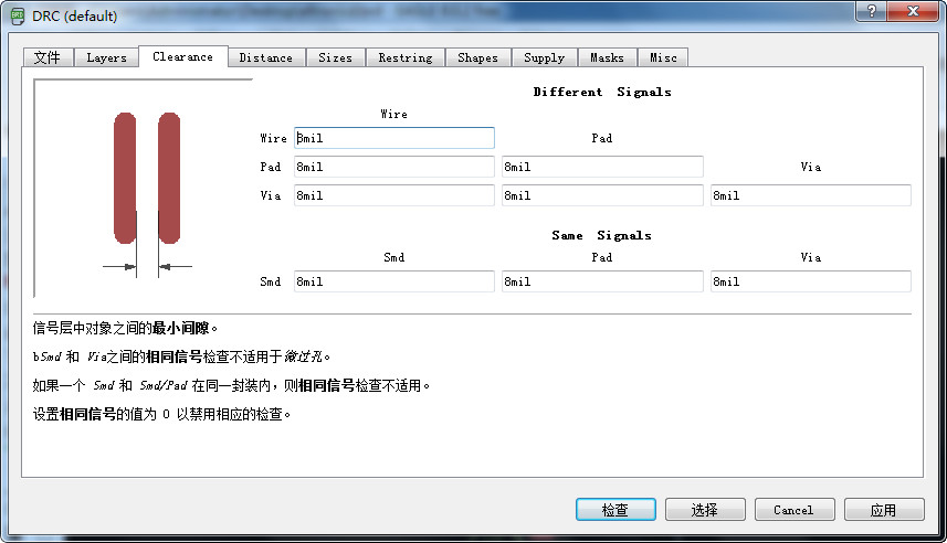
- Set the clearance, distance and sizes. All parameters in clearnance should set as 16 mil.
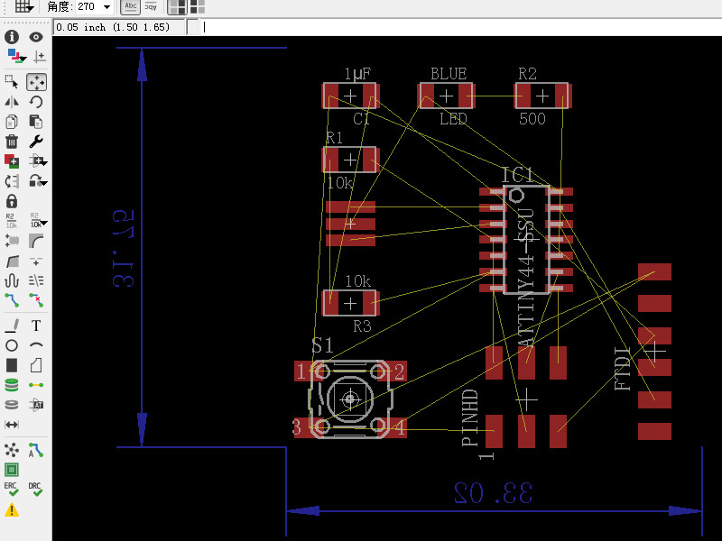
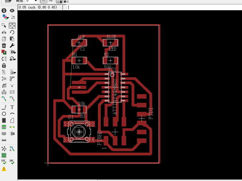
- Adjust the position of componets.
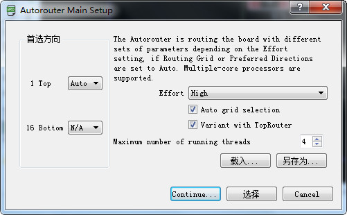
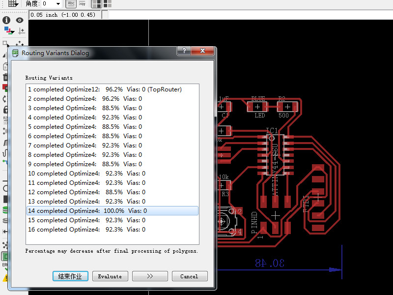
- Click on autorouter, the software will routing. Change the bottom to N/A and Effort choose High. Click on continue, and click on start.
- Routing completed find if there is 100%. If not adjust the position and try again.
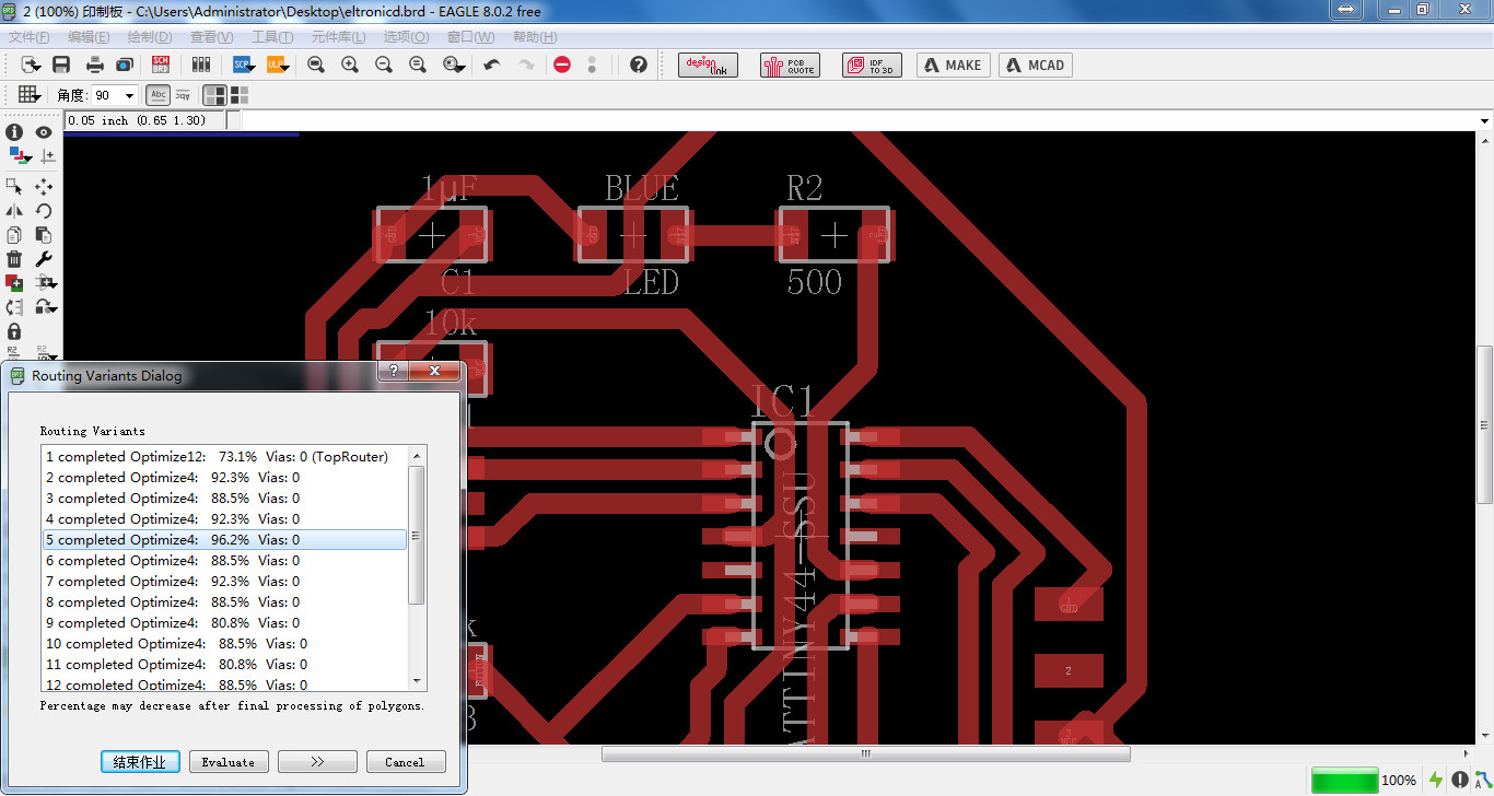
- No 100% was found, the highest is 96.2%. And one GND pin wasn't connected. I use 0 Ω resistor to connect so the VCC wire can go under the resistor and the GND can connect.
- Adjust the size of brd.
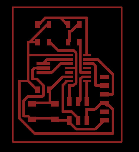
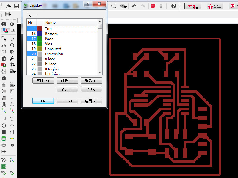
- Click on view and only show top pads and dimension.
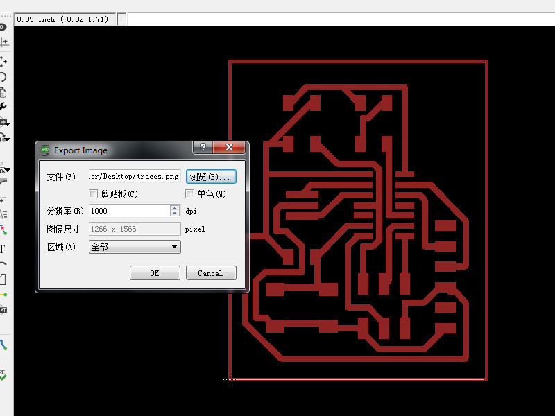
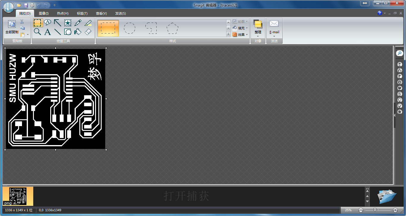
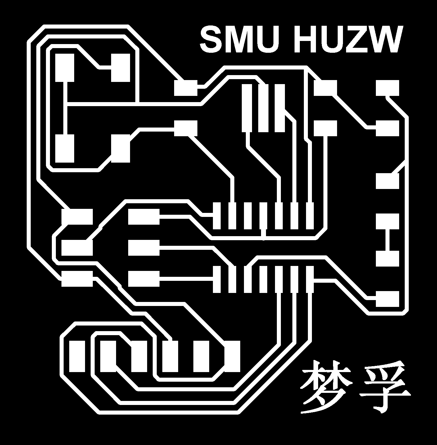
- Export a png and it can be recgonized by famodules. Click on export and choose png, name the png with traces and click on black and white, set DPI as 1000, area choose full. Then click on OK.
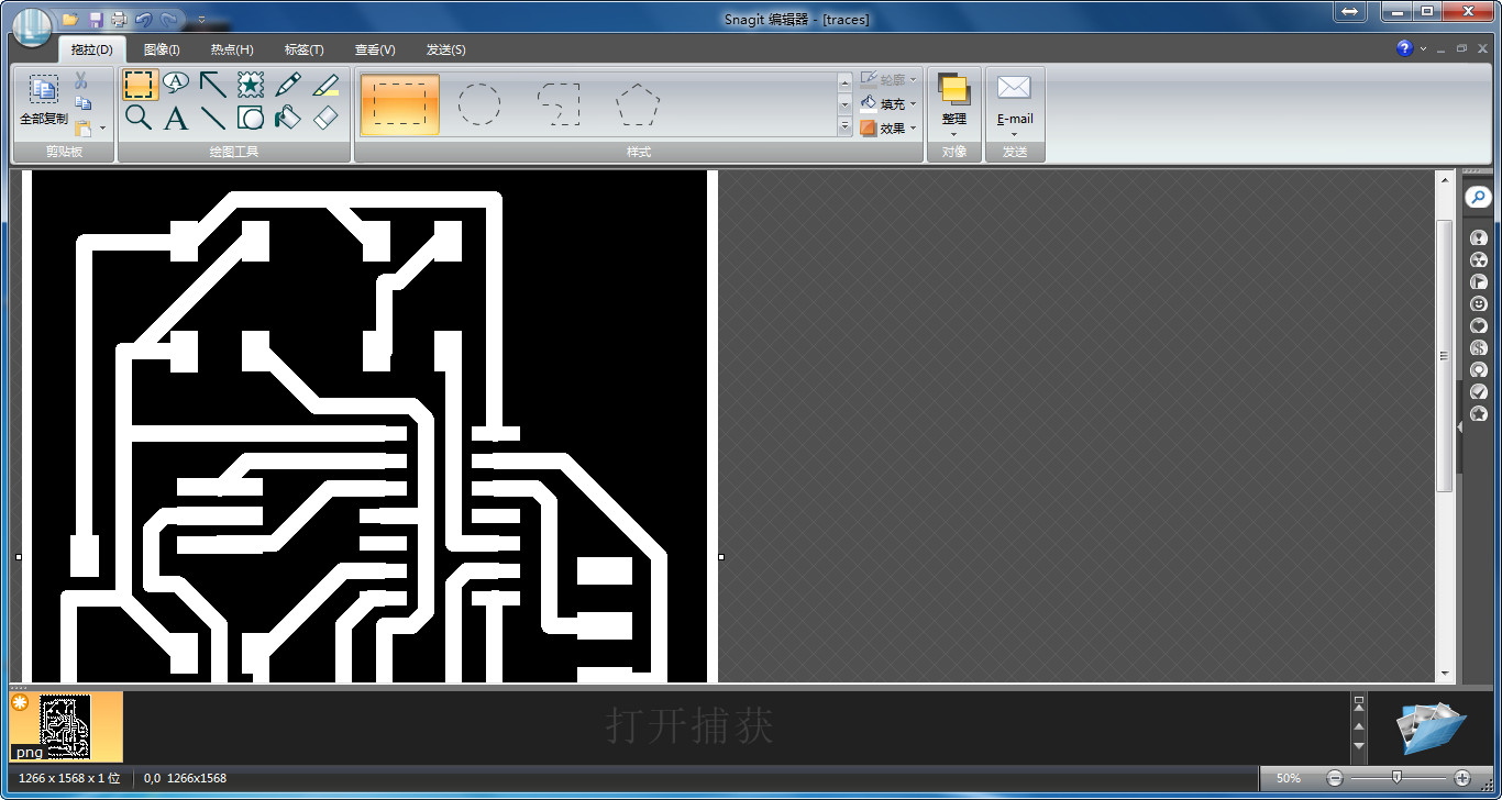
- Open the picture with a picture editor. I use Snagit. add the a wire and a posion for resistor. Save it.
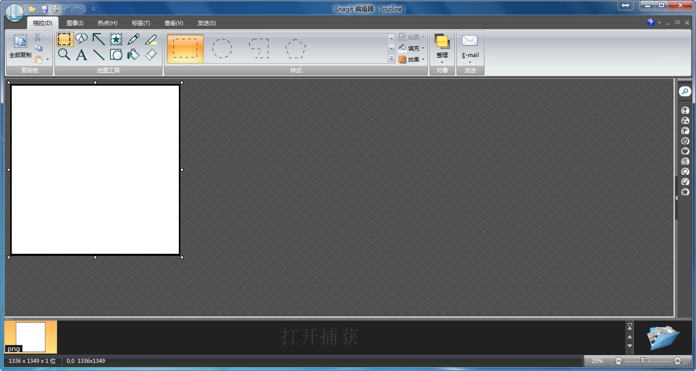
- Delete the picture and leave the boarder at least 1 mm. Save as outline.png.

- 3. Check and export.
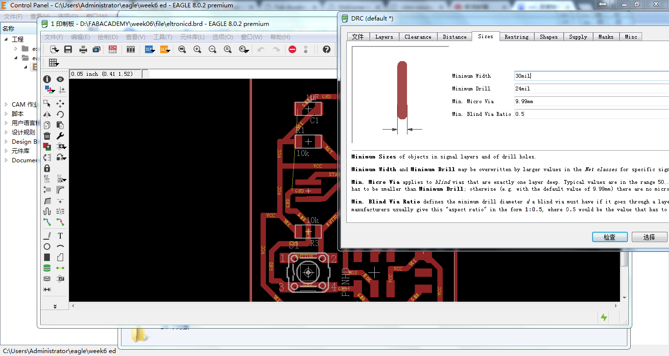
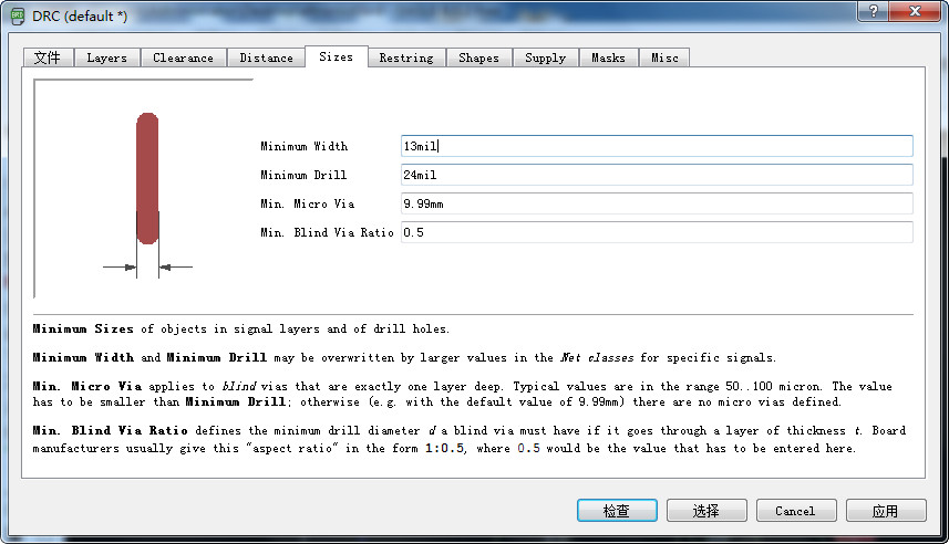
- I am confused why no 100% routing. So checked my work with instructor Saverio, the problem is the size of width of line setting.I set the minimum width in sizes setting as 30 mil almolst 0.762mm, it is two large. So I change it to 13 mil.
- Repeat autorouting. There is a 100% route.
- Setting the size.
- Export the png and do some edit on it.
- Make a outline png.
Part 2 Cut
- 1. Generate code.
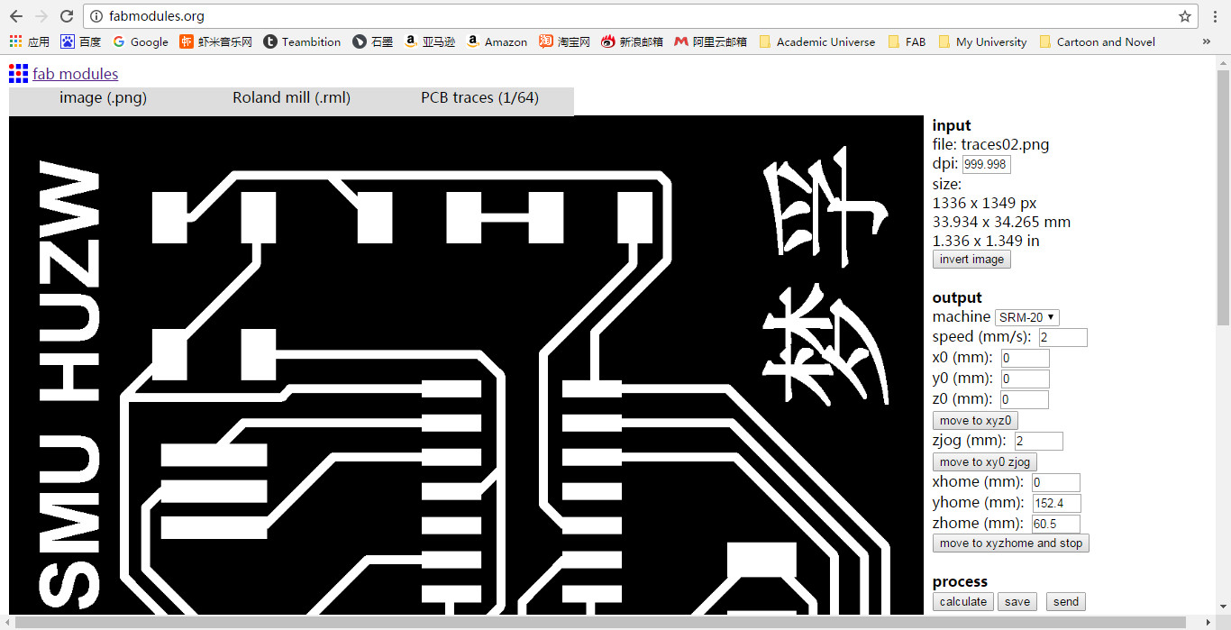
- Open the fabmodules input the png and choose the output format as rml set pcb traces 1/64. Choose the machine as SRM20. Set speed as 2mm/s and x0 y0 z0 should be 0. Caculate and check if it is ok save it. Generate code of outline.png as the same but the mill head should be 1/32, the speed set as 3mm/s.
- 2. Cut with Roland SRM20.
- Send the code to machine contrlled computer, and cut it.
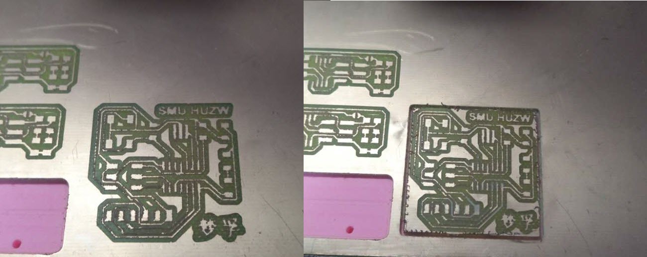
- Clean the pcb and make sure it is cut well.
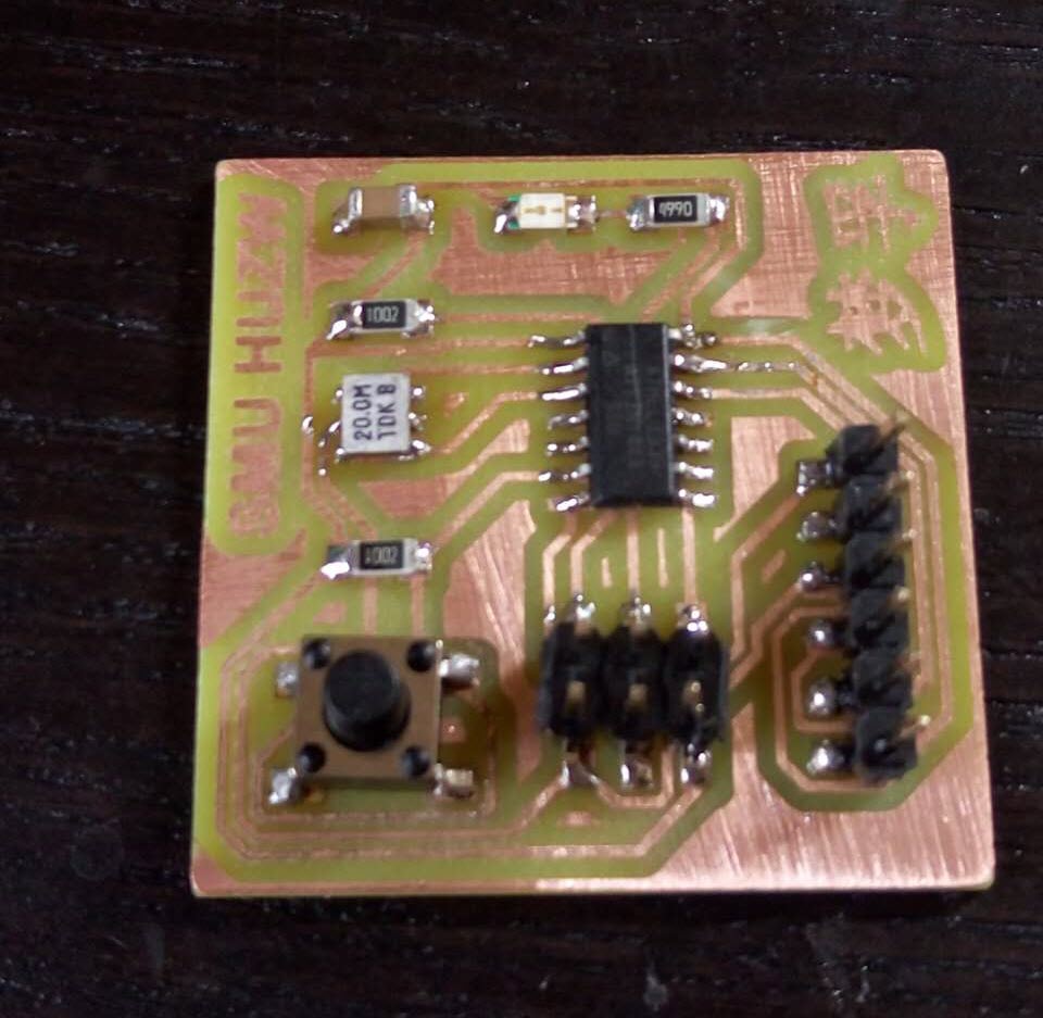
Part 3 Soldering
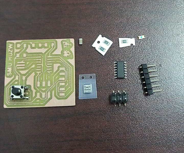
- 1. Preparing components.
- Find the components in the lab, we need these components as follow.
- 2. Soldering
- Take some mins to solder it.
- 3. Test.
- Before programming, I need a .c and make file go to the websiste. The hello.ftdi.44.echo.c and hello.ftdi.44.echo.c.make are the codes we need.
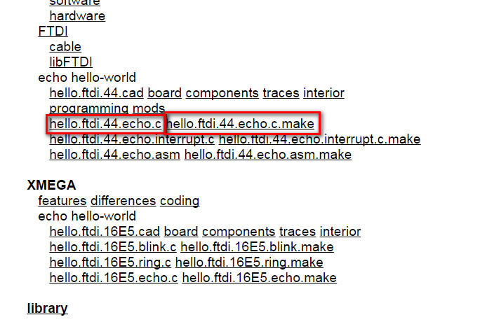
- Click it it show as web, save it as .c and .make.
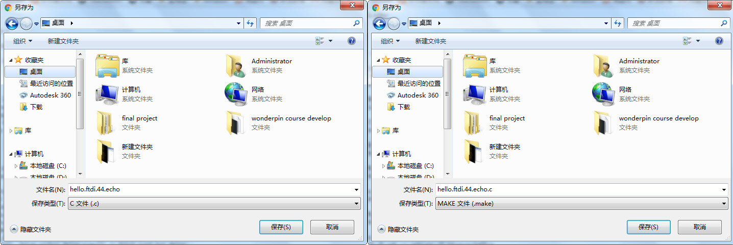
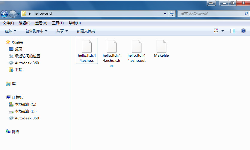
- Then rename the flile as hello.ftdi.44.echo.c and Makefile, then put them to a new folder called hellworld on desktop.
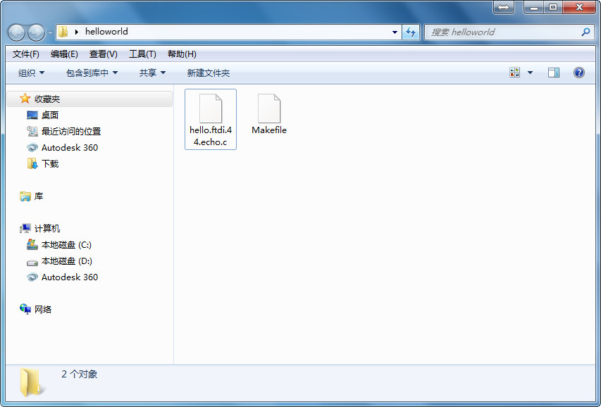
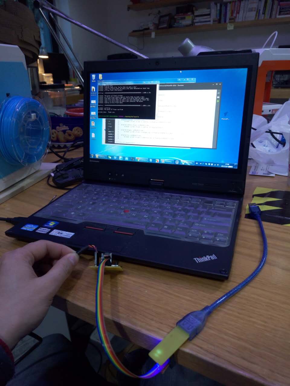
- Open Git Bash and cd to the helloworld folder, enter the command make. Before make connect the board and ISP to computer.
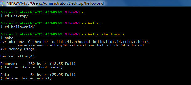
- Then two files was build in helloworld folder .hex and .out.
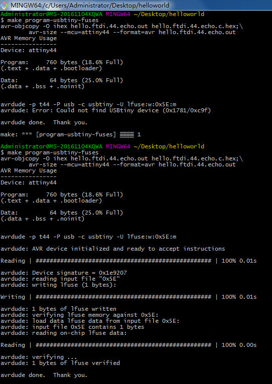
- According to the make file type command make program-usbtiny-fuses.
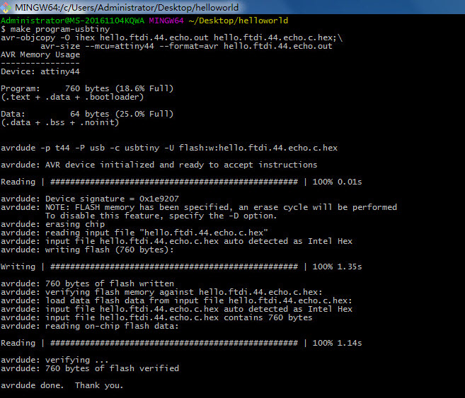
- Type command make program-usbtiny. It shows avrdude done Thank you. It is succeed.
- Programming test have done.