~ Input devices.
~ post date: 2017.4.30, recent update: 2017.6.2
I plan to use this week to begin prototyping components of my final project. I will be fabricating some biophotovoltaic fuel cells and want to be able to monitor environmental and energy harvesting properties of each cell. Ideally, that means constantly measuring lux, humidity, temperature and voltage (output) and logging that data to a spreadsheet.
Project files
Phototransistor breakout board
In a previous project based on an ATtiny44 I added an expansion pin on PA2 (ADC2/AIN1/PCINT2). I think I can use that pin to take readings from a phototransistor; making this a nice little project to get generate some momentum. Remember: spiral development.
First I examined Neil Gershenfeld's ATtiny45 schematic, the ATtiny45 datasheet, the ATtiny44 datasheet, andthe OP580DA phototransistor datasheet.
Because both pins are compatible with Analog to Digital Conversion (ADC), the phototransistor should work with my ATtiny44 board. The first step is to design a board for the phototransistor, resistor, voltage, ground, and logic connections. I use Autodesk's Eagle.
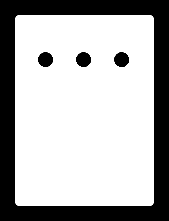
Relatively simple schematic. One thing to be aware. The phototransistor is directional. You can check the datasheet for that. Hint the chamferred corner aligns with the collector side.
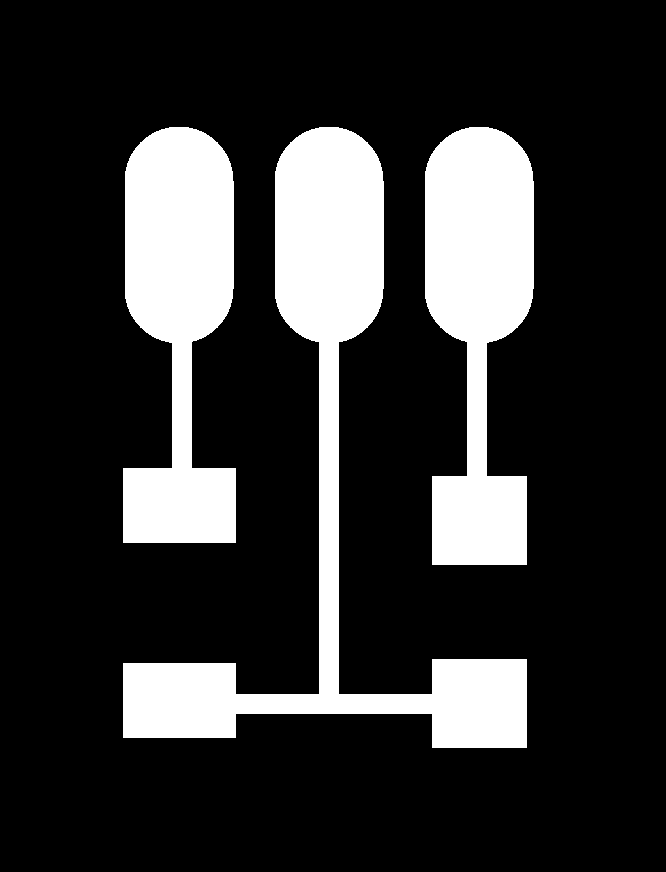
Out comes the traces and interior (linked below for download).
A quick milling job.
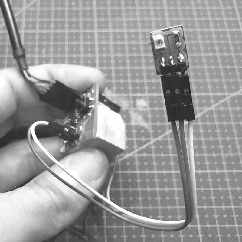
Cleaned up and stuffed.
Want to make one? You can do that.
Download project files
Phototransistor : reading
I will try a variety of programming languages until I get readings.
I am pulling VCC and Ground connections from the ISP so my order of operations: program with my fabISP, disconnect fabISP and connect phototransistor VCC and GND. That looks like this.
I thought this might be simple... I first tried this Arduino sketch for getting readings via the serial monitor. Unfortunately, I am not yet able to get any reading from the serial monitor, let alone light levels.
// Using an ATTiny44
#include <SoftwareSerial.h>
SoftwareSerial mySerial = SoftwareSerial (1,0);    // RX PA1 12, TX PA0 13

// Pin Configurations
const int SENSOR = A2;          // PA2
const int LED = A7;             // PA7
int sensorValue = 0;  // variable to store the value coming from the sensor


void setup() {
  // declare the LED as an OUTPUT:
  pinMode(LED, OUTPUT);
  mySerial.begin(115200);
  mySerial.println("I am here to serve.");
}

void loop() {                   // read the value from the sensor every 500 ms
  sensorValue = analogRead(SENSOR);
  mySerial.println(sensorValue);
  digitalWrite(LED, HIGH);      // Blink LED for visualizing sensor timing
  delay(250);
  digitalWrite(LED, LOW);
  delay(250);
}
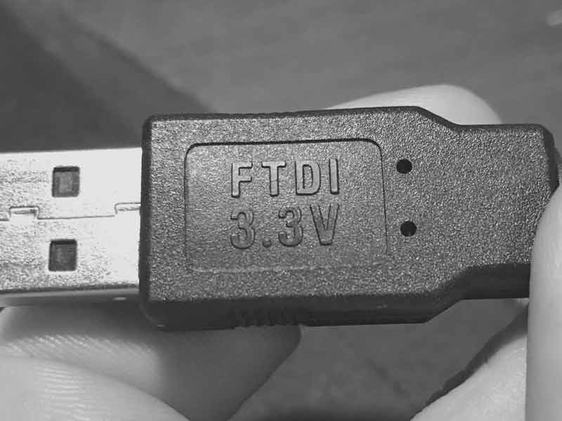
I tried to use a python serial monitor to no avail. Then, I returned to previous working code and uploaded the Echo : Hello World in C. This worked a few weeks ago in Python and Arduino serial monitors. Today, it is not working in either. I noticed that the FTDI serial number is different than the one I used previously. Upon inspecting the cable, I see it is 3.3Volts. I feel like I just wasted two hours. This project will have to wait until I return to the lab tomorrow to grab a 5V FTDI cable.
Upon returning to the lab, I switched to a 5V FTDI cable and confirmed the serial monitor working with the Echo: Hello World C program using a PySerial and Arduino Serial. Then I went about uploading an arduino sketch using Arduino's SoftwareSerial library. I wrote this for testing the serial.
// Using an ATTiny44
#include <SoftwareSerial.h>
SoftwareSerial mySerial(0,1);     // RX PA1 12, TX PA0 13 (flipped)

void setup() {
  mySerial.begin(19200);          // start serial feed, set the baud rate
}

void loop() {                     // print hello every 250ms
  mySerial.println("hello");
  delay(250);
}
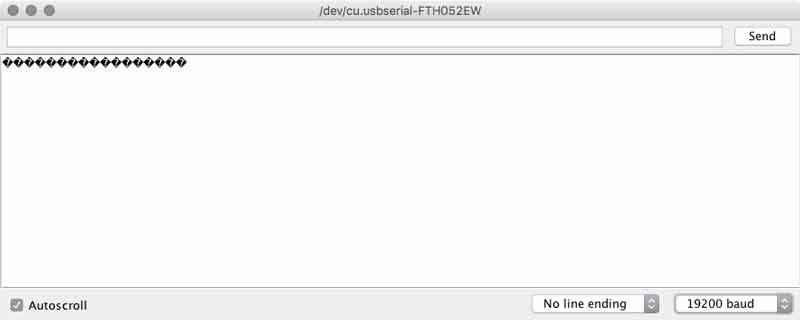
I was able to get readings from the serial monitor, but mostly black diamonds with a white question mark.
I thought something must be wrong with the baud rate so I began experimenting with different rates and also using the internal versus external clocks. By chance or shear exhaustion, I found setting the serial baud to 19200 in Arduino and 2400 on the serial monitor to report my expectation.
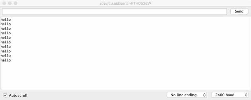
With those adjustments, I uploaded the previous code I modified for the phototransistor and it worked.
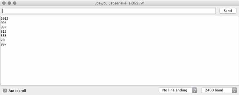
I noticed some students used a 49.9kOhm resistor on the Phototransistor to get more sensitive measurements. I replaced the 10KOhm resistor on my baord to see what would happen. This page explains the effect of resistors on phototransistors. With the same arduino code...
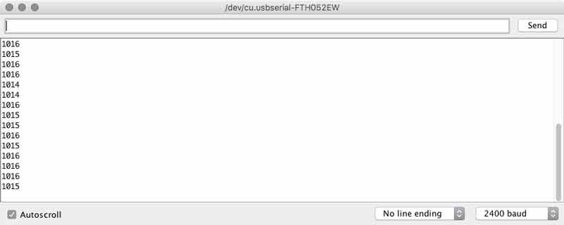
The range of readings from the brightest light to no light was only from 1011 to 1016. I checked the signal on our oscilliscope and found parity with the serial monitor. Then, in the process of tinkering I snapped the single pin header and much of the copper trace from my ATtiny44 board. While I was fixing that, I went back to the 10KOhm resistor on the phototransistor. We have adjustable resistors in the lab, it will be interesting to setup an experiment with one in the future.
I returned to the code and added a feature to convert the sensor values to a percentage of its total spectrum, making it easier to understand for us humans.
#include <SoftwareSerial.h>
SoftwareSerial mySerial(0,1);         // RX PA1 12, TX PA0 13 (flipped)

// Using an ATTiny44
// Pin Configurations
const int sensorPin = A2;             // PA2 11 ADC2
const int LED = A7;                   // PA7 6
int sensorValue = 0;                  // variable to store the value coming from the sensor
int outputValue = 0;                  // variable to store the PWM


void setup() {
  pinMode(LED, OUTPUT);               // declare the LED as an OUTPUT:
  mySerial.begin(19200);              // I set this to 19200 and arduino monitor to 2400
  mySerial.println("Hello");
}

void loop() {
  sensorValue = analogRead(sensorPin);// read Phototransistor write to variable
  outputValue = map(sensorValue, 0, 1023, 0, 100);  // convert to a percentage
  mySerial.print("sensor ");
  mySerial.print(sensorValue);        // send reading to serial
  mySerial.print("...output ");
  mySerial.println(outputValue);      // send percentage to serial
  digitalWrite(LED, HIGH);            // visually confirm read timing
  delay(125);                         // pause between readings (not too fast for stability)
  digitalWrite(LED, LOW);
  delay(125);
}
That worked alright and it gave me an idea. How about having the sensor calibrate the percentages by the brightest light during its measurements?
#include <SoftwareSerial.h>
SoftwareSerial mySerial(0,1);         // RX PA1 12, TX PA0 13 (flipped)

// Using an ATTiny44
// Pin Configurations
const int sensorPin = A2;             // PA2 11 ADC2
const int LED = A7;                   // PA7 6
const int timer = 125;
int sensorValue = 0;                  // variable to store the value coming from the sensor
int outputValue = 0;                  // variable to store the PWM
int lightMax = 1023;                  // variable to calibrate percentage
int countdown = 0;

void setup() {
  pinMode(LED, OUTPUT);               // declare the LED as an OUTPUT:
  mySerial.begin(19200);              // I set this to 19200 and arduino monitor to 2400
  delay(1250);                        // delay 20 seconds to connect phototransistor
  while(countdown < 5) {              // flashing light last ten seconds before start
    countdown++;
    digitalWrite(LED, HIGH);
    delay(125);
    digitalWrite(LED, LOW);
    delay(125);
  }
  mySerial.println("Hi");
}

void loop() {
  int sensorValue = analogRead(sensorPin);// read Phototransistor write to variable
  if (sensorValue >= lightMax) {
    int outputValue = map(sensorValue, lightMax, 1023, 100, 0);
    mySerial.print(sensorValue);        // send reading to serial
    mySerial.print(".....");
    mySerial.println(outputValue);      // send percentage to serial
    delay(timer);                       // pause between readings (not too fast for stability)
  } else {                              // calibrate percentage
    mySerial.print(sensorValue);
    mySerial.println(" XXX");
    lightMax = sensorValue;
    digitalWrite(LED, HIGH);             // visually confirm calibration
    delay(timer*2);
    digitalWrite(LED, LOW);
  }
}
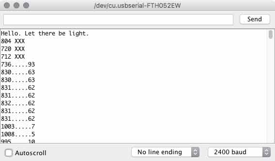
Like with the LCD, custom characters printed to the serial monitor use many precious bits. I found myself shortening those prompts as my sketch grew. I added a short delay (with flashing light) in the setup to give me time to swap out the ISP cable and attach the VCC and Ground to my phototransistor board. With an If...else conditional I setup a variable to adjust to the brightest light and subsequently calibrate the percentage conversion.
Next I tried making a sketch to work with the switch. I fished out my previous switch script and went to work.
#include <SoftwareSerial.h>
SoftwareSerial mySerial(0,1);         // RX PA1 12, TX PA0 13 (flipped)

// Using an ATTiny44
// Pin Configurations
const int switchPin = A3;             // PA3 10 ADC3
const int sensorPin = A2;             // PA2 11 ADC2
const int LED = A7;                   // PA7 6
const int timer = 125;
int sensorValue = 0;                  // variable to store the value coming from the sensor
int outputValue = 0;                  // variable to store the PWM
int countdown = 5;                    // set countdown equal to checks
const int checks = 5;
boolean lastSwitch = LOW;
boolean currentSwitch = LOW;


void setup() {
  pinMode(LED, OUTPUT);               // declare the LED as an OUTPUT:
  mySerial.begin(19200);              // I set this to 19200 and arduino monitor to 2400
  mySerial.println("Illuminate me.");
}

boolean debounce(boolean last)
{
  boolean current = digitalRead(switchPin);
  if (last != current)
  {
    delay(5);
    current = digitalRead(switchPin);
  }
  return current;
}

void loop() {
  currentSwitch = debounce(lastSwitch); // press button to push five readings to serial.
  if (lastSwitch == LOW && currentSwitch == HIGH)
  {
    mySerial.println("ok");
    digitalWrite(LED, HIGH);             // delay to clear hand
    delay(375);
    digitalWrite(LED, LOW);
    while(countdown < checks) {          // five checks
      countdown++;
      int sensorValue = analogRead(sensorPin);// read Phototransistor write to variable
      int outputValue = map(sensorValue, 0, 1023, 100, 0);
      mySerial.print(sensorValue);       // send reading to serial
      mySerial.print(".....");
      mySerial.println(outputValue);     // send percentage of total spectrum to serial
      delay(timer);
    }
    mySerial.println("done");
  }
  lastSwitch = currentSwitch;
  countdown = 0;                          // reset while loop count
}
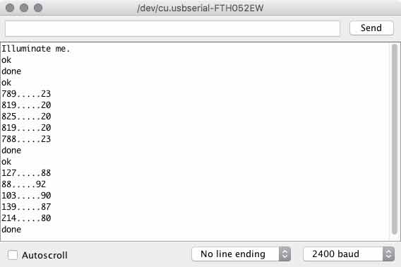
When you press the button, there is a brief delay with LED indicator for you to move your hand away from the phototransistor. Then five readings will be transmitted to the serial port. Rinse and await another button press.
The next step will be to add sensors and functionality for measuring voltage output, humidity and temperature (and possibly soil moisture because I found a sensor in the lab). Further, I need this information passively logged into a datasheet for analysis. I think I will start in on these tomorrow.
Download project files
I will post links to resources I have found helpful here.
Python : A start
Having now worked with Arduino, Processing, Grasshopper, HTML, and CSS, I feel confident to begin learning Python. Experienced programmers agree that the highest levels of machine instruction are capable with these advanced programming languages. Therefore, I think it best to dive in and start learning something with the widest horizon. To be clear, while this is an objective I have started near the end of the Fab Academy cycle (in week 17 now), learning and using will carry me beyond. Because I intend to carry on with this blog after completion of the course, I am starting an entry to track my work here.
Why Python? Start with this roadmap. It is easy to find on the web if this is difficult to read. I am selecting Python first because it is said to be easy, best for beginners, widely supported, can be used to extend applications I use regularly such as Grasshopper, Rhinoceros and Maya, Processing, even web development, is often recommended by Neil Gershenfeld, to name a few reasons.

I started with the Fab Academy Python Tutorials. This is an excellent primer which will give you guidance on the applications your computer needs, Python uses, etc.
I will post links to resources I have found helpful here.
Jump : Index
J.travis Russett © 2017
 All the work contained within is licensed under a Creative Commons Attribution-NonCommercial-ShareAlike 4.0 International (CC BY-NC-SA 4.0) License
You may remix, tweak, and build upon my work non-commercially, as long as you credit me and license your new creations under the identical terms.