Until 8 Mar 2017
Electronics Design
Contents
- Circuit board design using Eagle!
- Making the physical board
- Programming Hello Kuri Board
- 6th The Fab Academy meeting
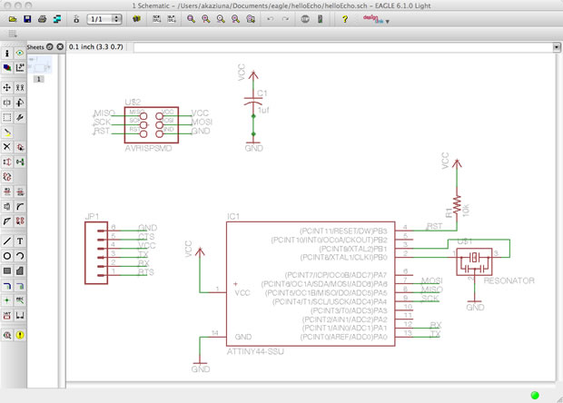
Electronic Design using EAGLE(Easily Applicable Graphical Layout Editor)
Sparkfun's EAGLE tutorial: Schematic
Sparkfun's EAGLE tutorial: Board
Tutorial on electronics design using Eagle
Original the Fab Academy 'echo hello-world board'
Schematic (.sch) - logical components
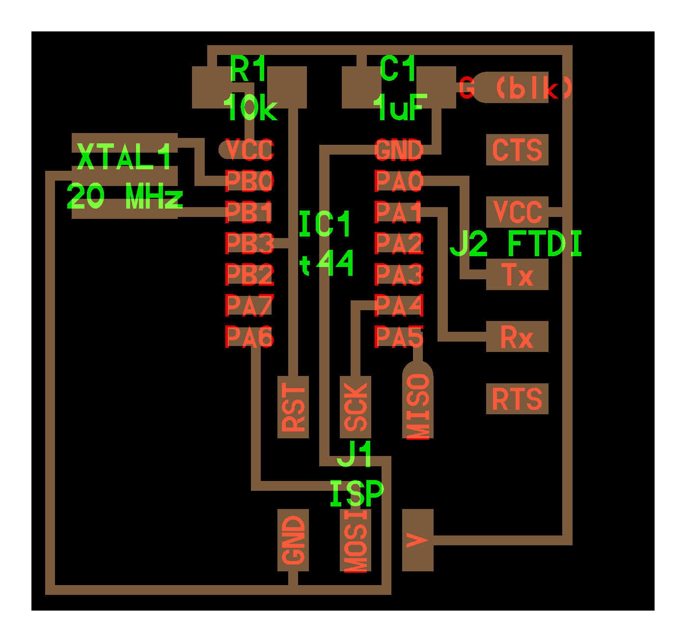
Board Layout (.brd) for the actual board that we mill
Board
I need to add LED and a botton, than redesign.
Eagle
First I've download and installed the Fab Component Libary.
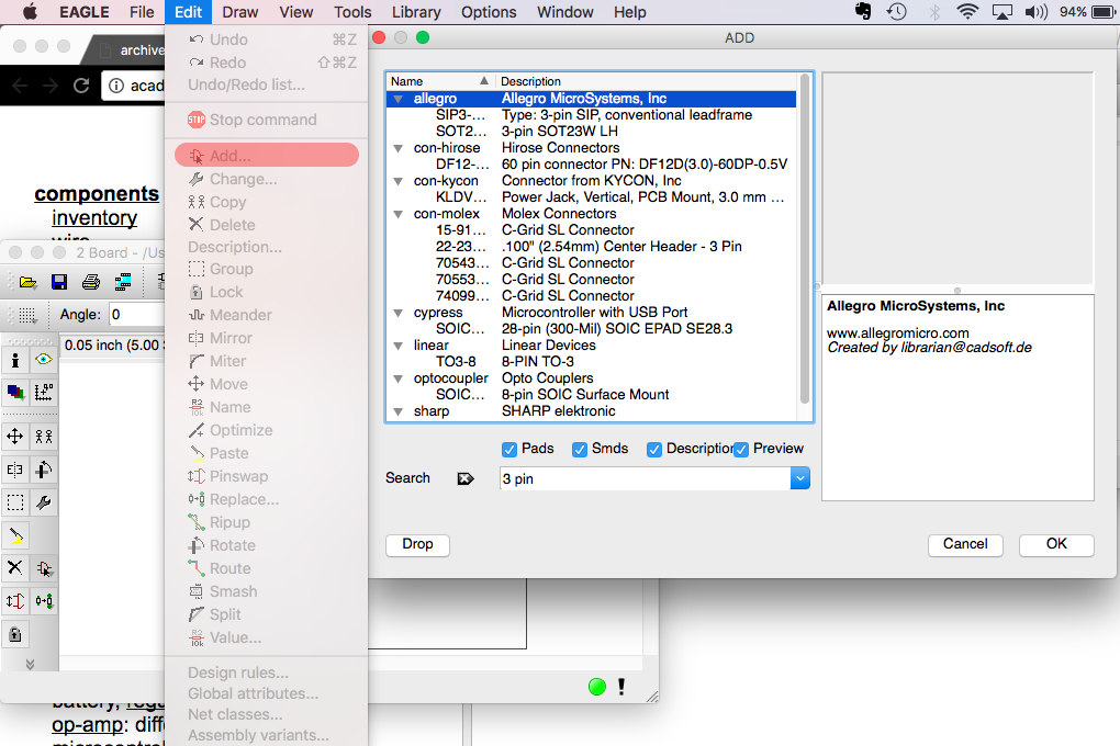
After adding all the components in schematics,
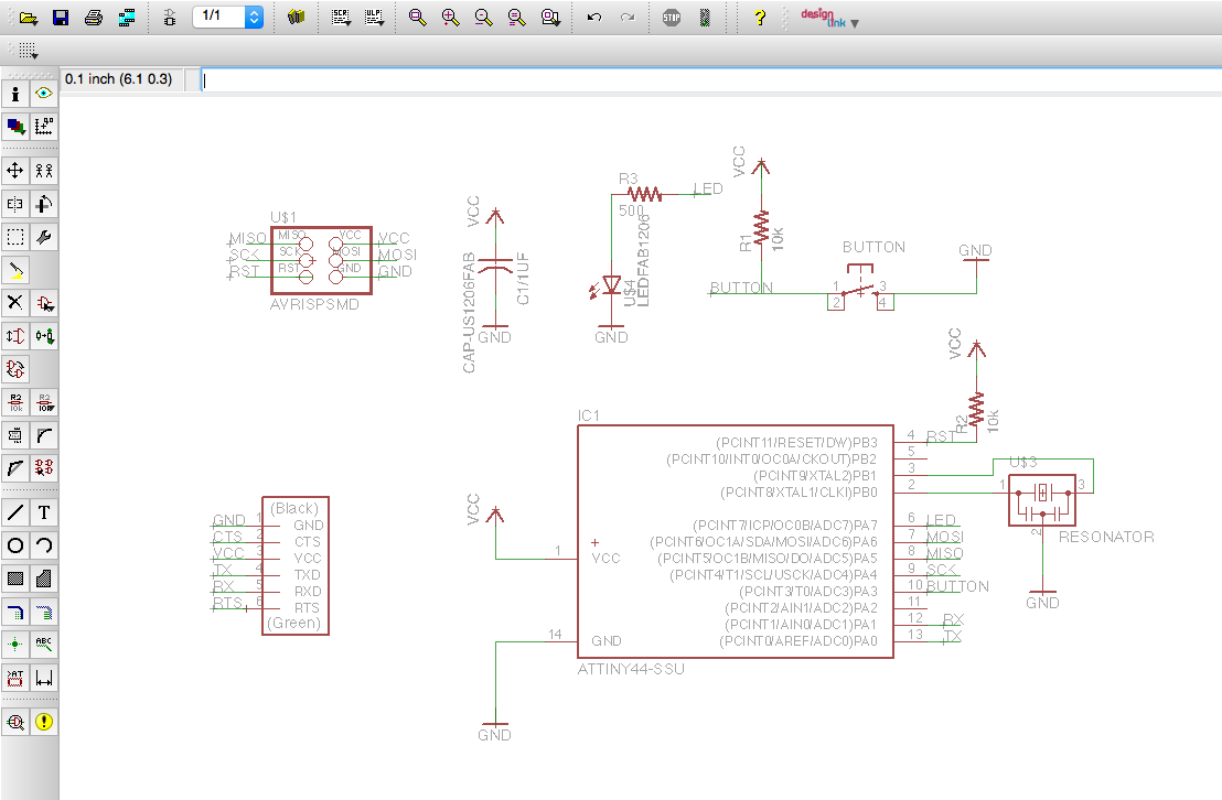
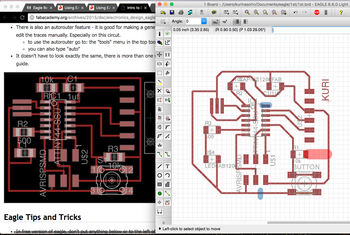
Rearrange components, I was looking at the reference board. However, after arranging the board, I reallized that some parts were missing.
Rodrigo told me about JOIN in schematics. After joining all parts, I was able to fix some errors.
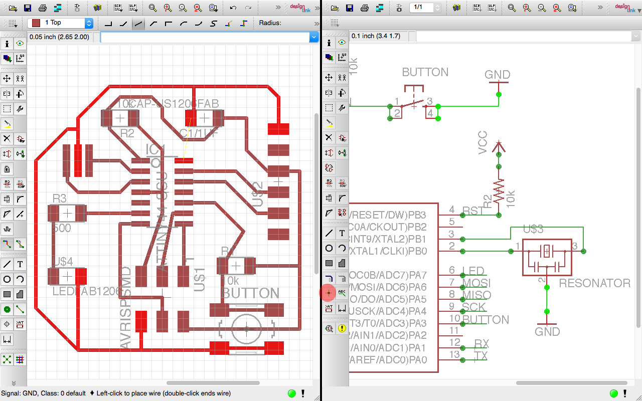
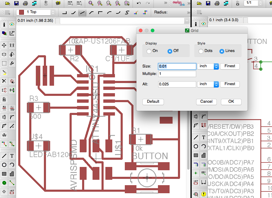
to fix two lines below attiny 44, I had to change value in GRID.
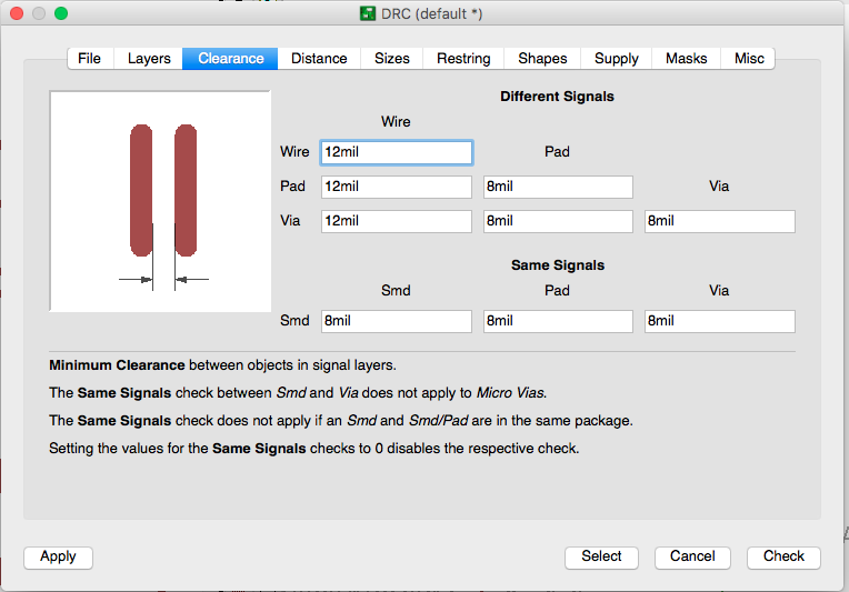
Checking Design Rules,
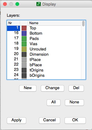
Before saving, DISPLAY and only allow TOP layer to show.
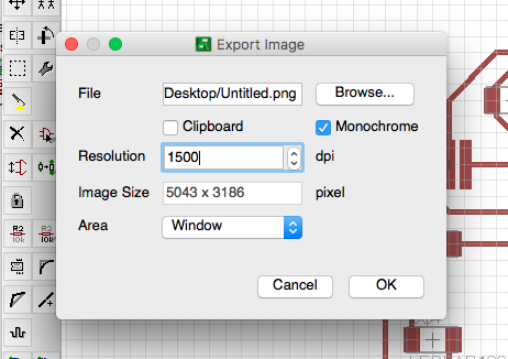
Export the file into image. High resolution, and select monochrome.
- Eagle .brd file
- Eagle .sch file
Fab Module
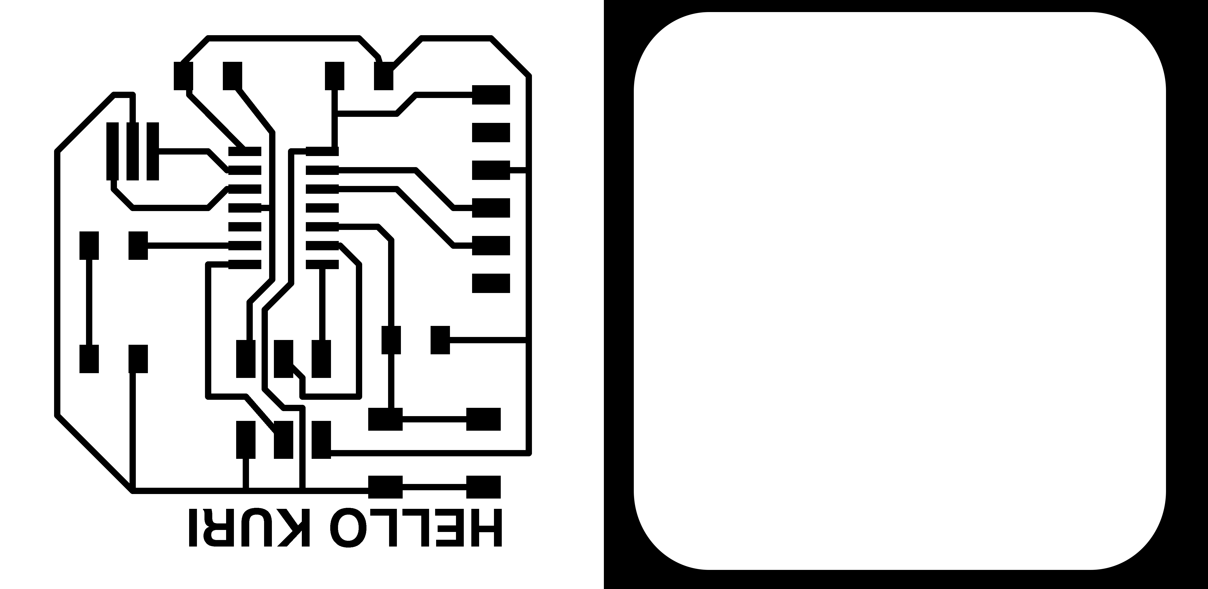
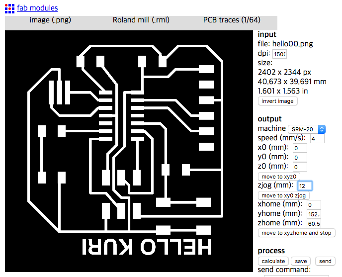
No big errors
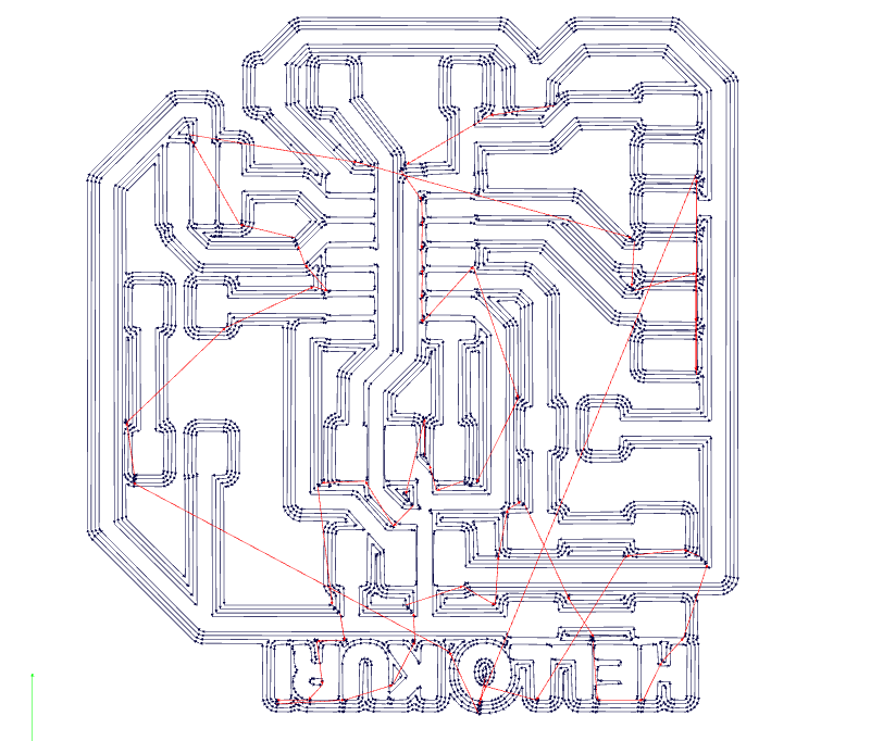
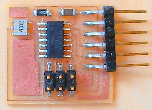
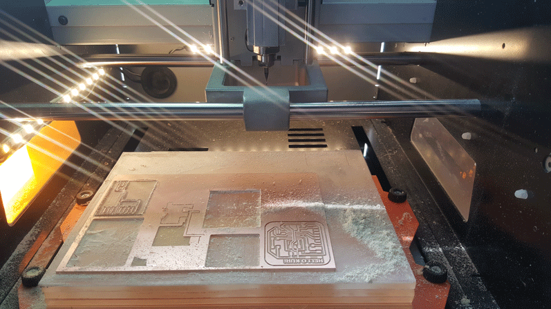
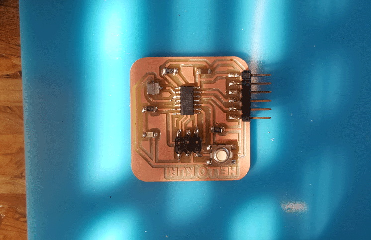
Making the physical board
I had to disconnect that little part.
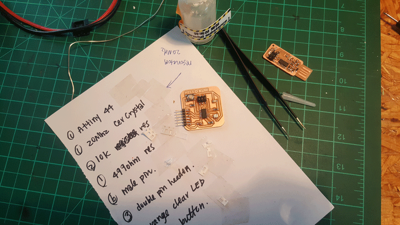
1 - Attiny 44
1 - Resonator 20Mhz
2 - 10k register
1 - 499ohm register
6 - male pin-header
3 - double pin-header
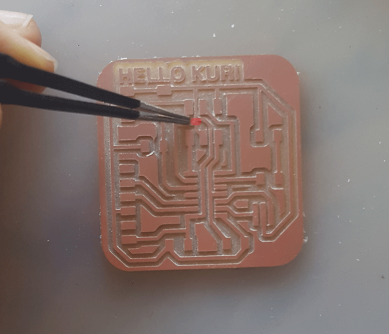
1 - Orange clear LED
1 - 6mm button
1 - CAP 1uf
NOTES:
CURRENT is the directed flow of charge through a conductor.
VOLTAGE is the force that generates the current.
RESISTANCE is an opposition to current that is provided by a material, component, or circuit.
After checking with multimeter, I realized that I had two part of capacitor connected.
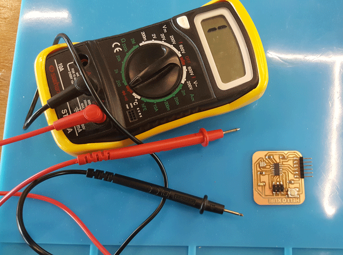
After re-soldering = DONE!
Programming Hello Kuri Board
Reference: High-low tech website
Installing ATtiny in Arduino
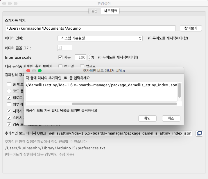
Open the preference in the Arduino. At the bottom of the dialog, "Additional Boards Manager URLs and type in
https://raw.githubusercontent.com/damellis/attiny/ide-1.6.x-boards-manager/package_damellis_attiny_index.json
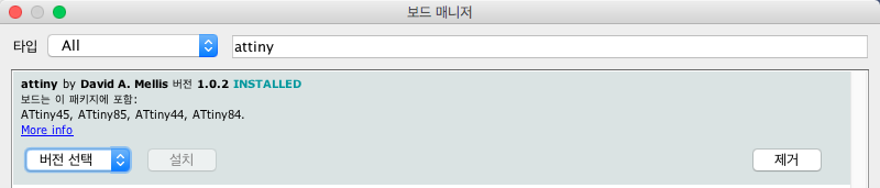
Open the boards manager in the TOOL < BOARD
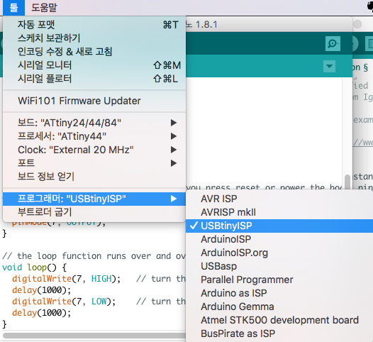
Set up the TOOL < Board, processer, clock, and programer < ATtiny 44, ATtiny44, External 20 MHz. Also, don't forget PROGRAMMER: USBtinyISP.
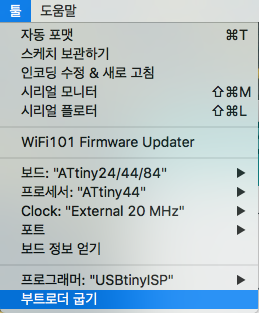
After connecting the hello board to the computer, TOOL < BURN BOOTLOADER
We are using Arduino program, but we don't have same amount of pins.
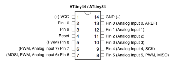
With the Arduino program I changed Blink and Button code according to the pins in ATtiny.
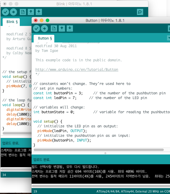
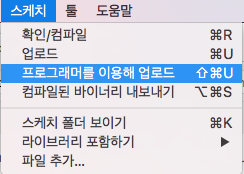
Instead of just uploading, UPLOAD USING PROGRAMER
Yay! Blink + button works!
6th Meeting:
Electronic Design March 1, 2017 11pm~2am(Seoul)
Homework
o - Show your process using words/images/screenshots
o - Explained problems and how you fixed them
o - Redraw the Echo hello-world board,
o - Add (at least) a button and LED (with current-limiting resistor)
o - Check the design rules, make it, and test it
o - Included original design files (Eagle, KiCad, or Inkscape)