
For this week, the assignments to be accomplish are:
I started reading the Attiny44 Data Sheet and I learn that Attiny44 is a 12 I/O pin wich 8 from them are ADC (Analog to Digital coverter), this AVR can run in a voltage between 2.7V to 5.5Volts and can be clock up to 20Mhz.

This information was too much to understand in a limited time, So, I went back to my trusworthy Youtube friend and try to look for anything related to AVR Programming and ISP.
And actually I am surprise that there's so much information if you know how to look for it, like form example this video Programming AVR explain a lot of things and I was actually able to understand (not everything) and I am confident that I will be getting used to this in no time.
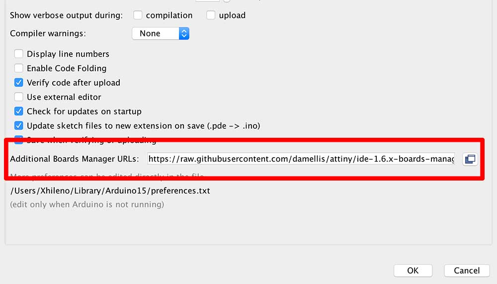
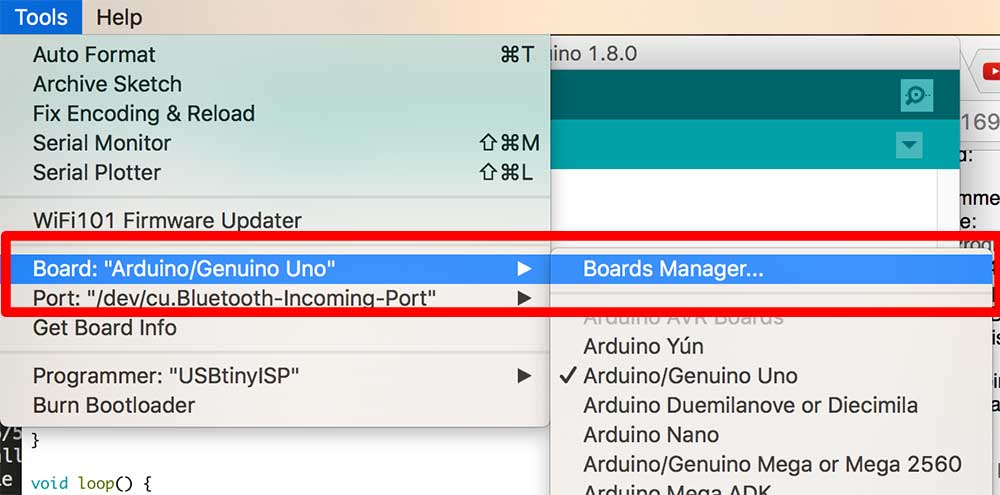
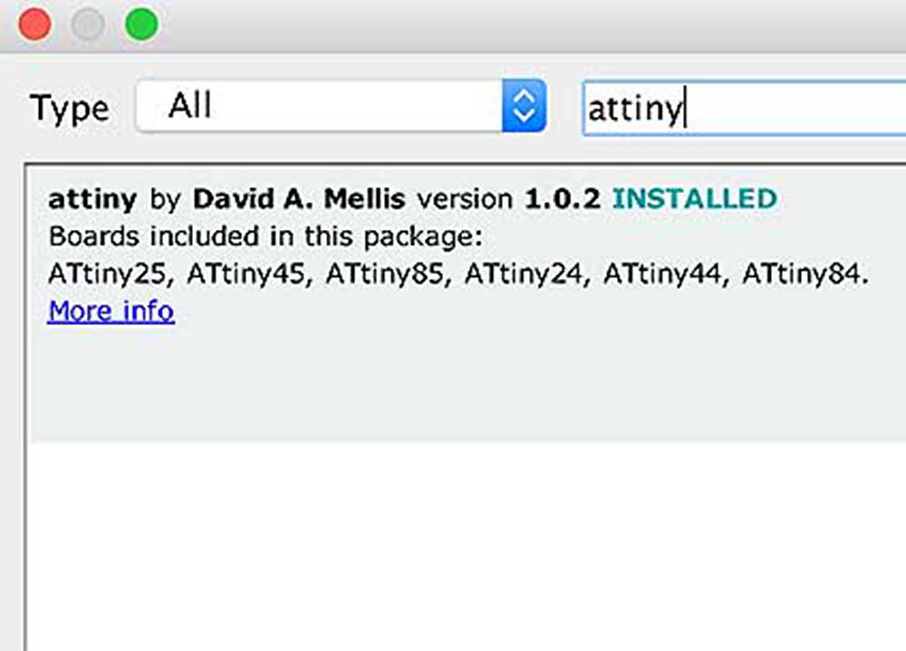
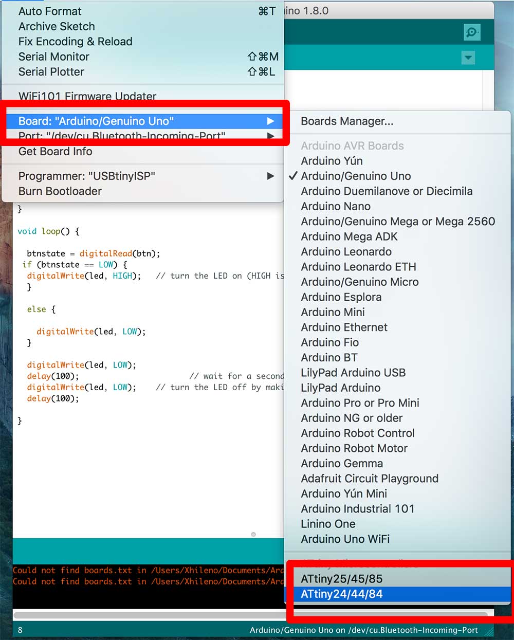
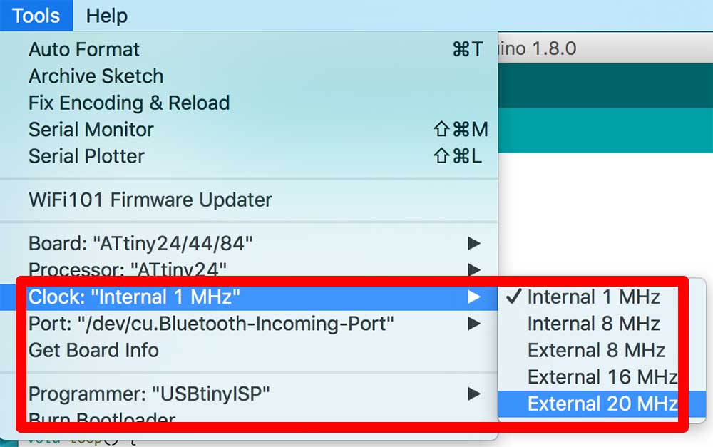
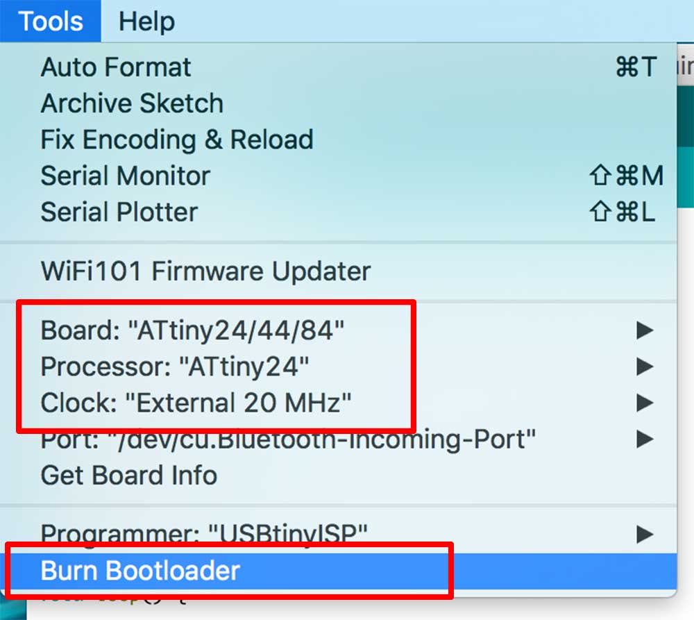
Using the ARDUINO IDE, For bootloading the Hello board, its highly recommended to read the highlowtech.org, I followed it step by step and it worked the first try! see some picture below.
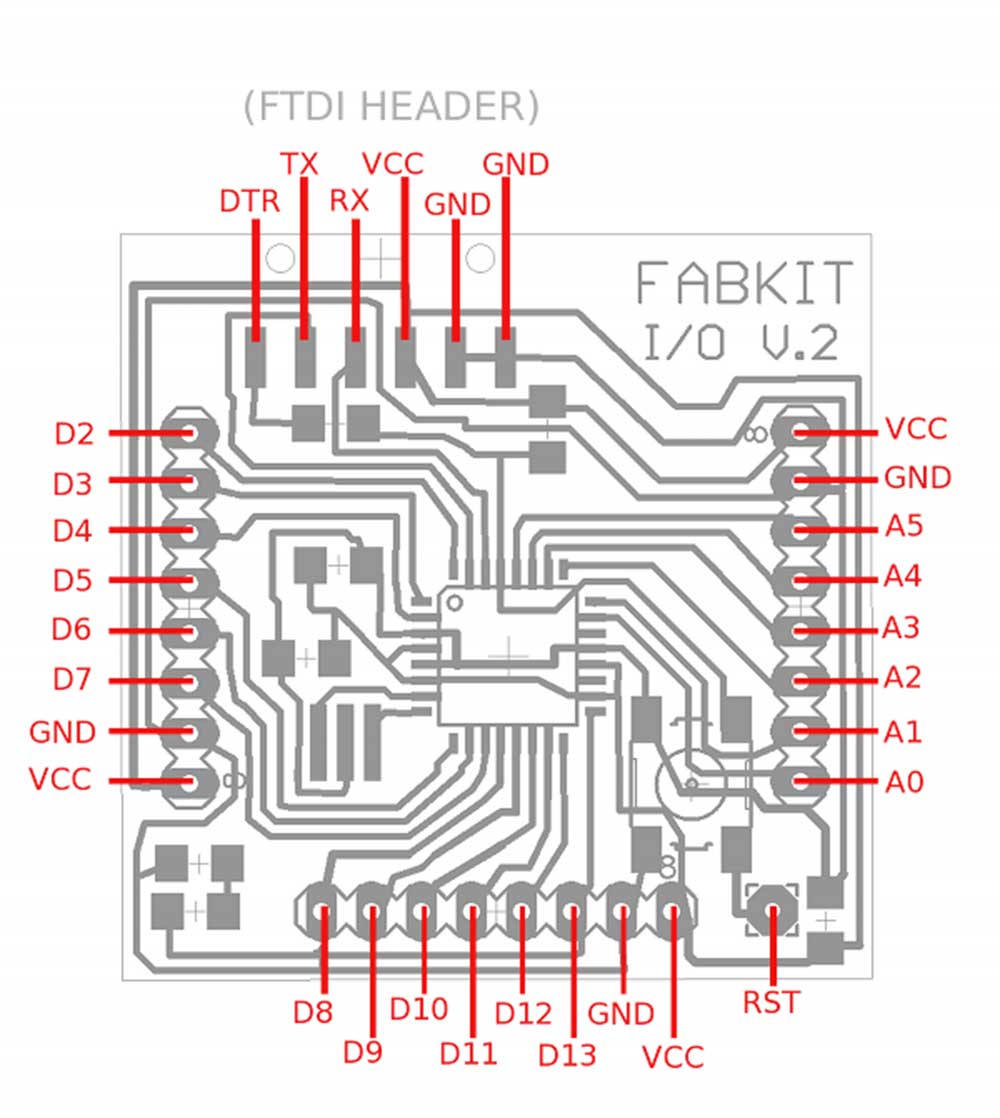
This time I choose the Fabkit i/o (aka Fabduino), so I just followed the tutorial soldering all the componest listed below.
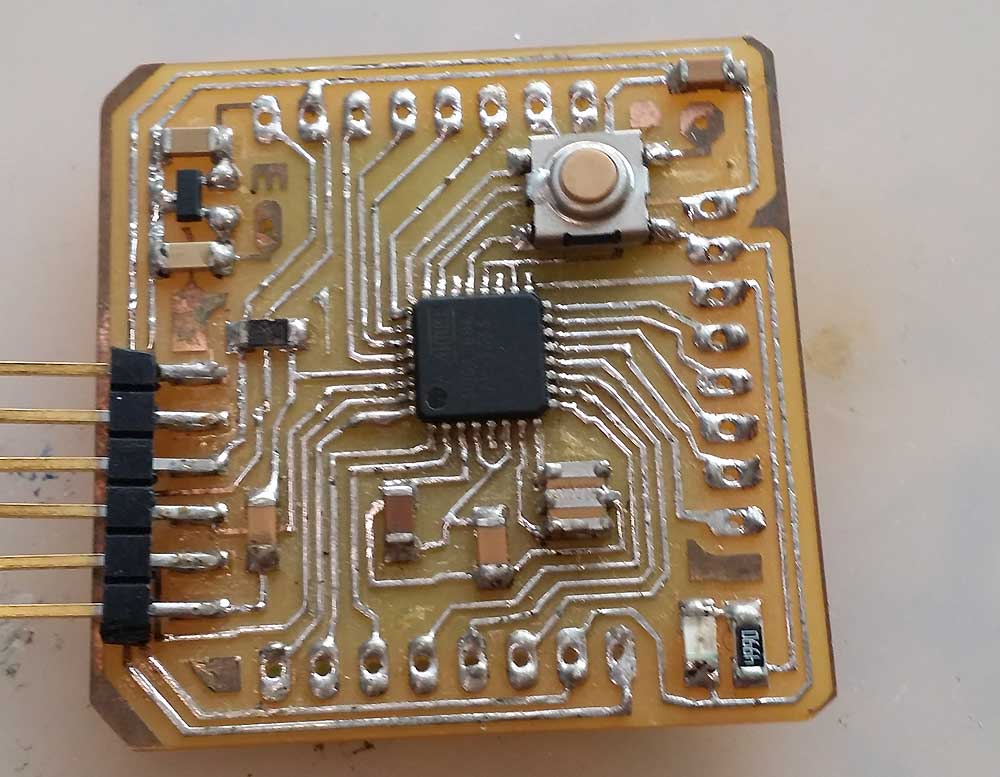
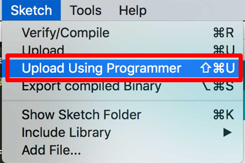
I soldered the parts with no shorts and even I made a new ISP since the USB connection from Brian's Board were very unstable and I try to program it.
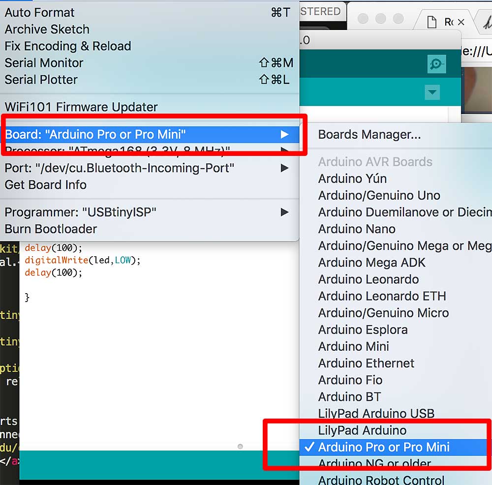
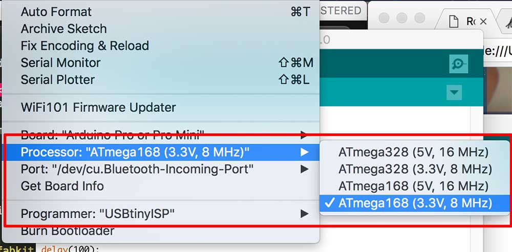
As we can see above I did all the necessary changes to the IDE to prepare the bootloader, but for some reason It asked me to double check the connections.(forgot to take a picture)
Two days passed and I did all in my power to fix the board by resoldering the components again, check continuity on the cables looking for shorts but nothing happend. I suddenly our instructor said let's check and he took the MCU out and change for another one and voila!! it worked at the first try loading bootloader. ( I was angry because it felt really unfair) but something stranged happend Kurina had the same problem, so Our instructor checked the MCU itself and discover that for some reason the MCU add different label numbers on it.
we needed it MEGA168U2-AU instead of MEGA168-15AT.
NOTE!! always remember to check the components before you solder them!!
My first intuition was to use the same code that I use to blink the Hello world two weeks ago, so I did and nothing happend..
Therefore, the question was what I/O pin is connected the built-in led of this board?
First I looked for it in the squematics.
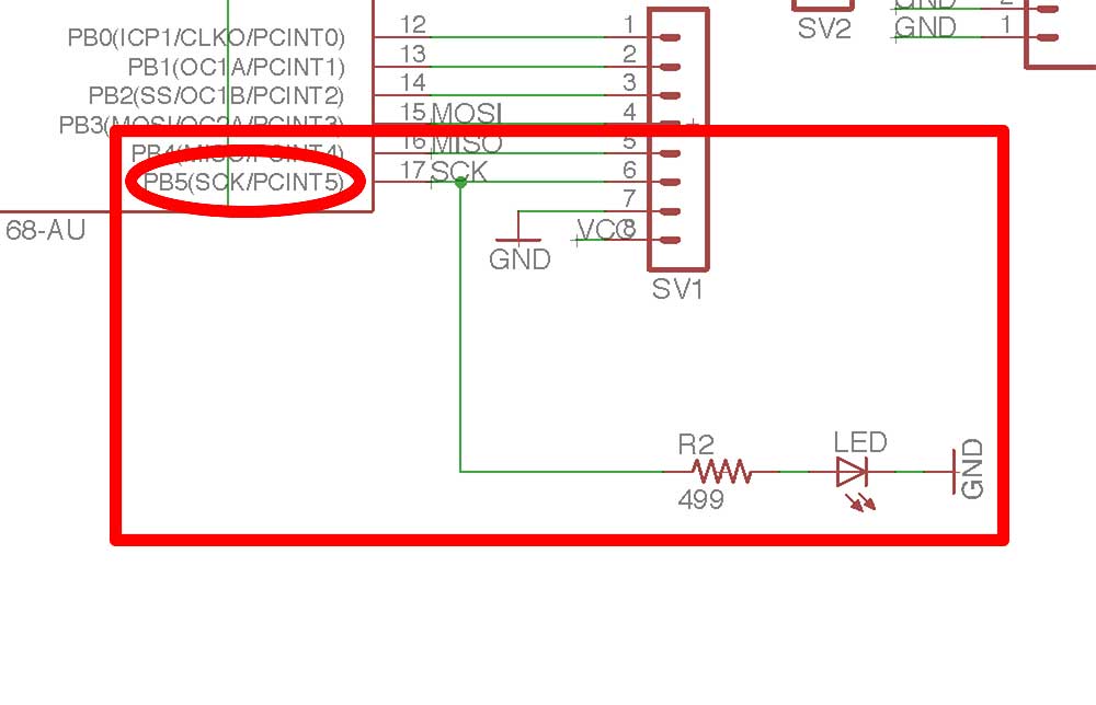
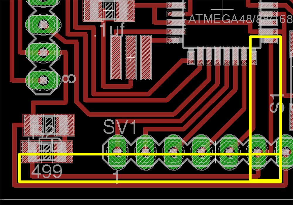
So, I used digital I/O 5 as I can see in the Squematics. But again didn't work.
So I argued with my instructor that this was not logical since the LED worked in the digital I/O 13; but It was not specified in the squematics.

Since the Arduino IDE is the one uploading the bootloader, this will define pins different than others IDEs like the ATMel AVR. ( I really need to check this)
So, as defined in the "Arduino PINOUT diagram" I used pin 13; and I worked just fine.
What I was not able to do this week:
What I did but need to get better at:
