For this week, the assignments to be accomplish are:
Learn how to use The small CNC (roland)
Chose a ISP board and cut it
Learn about SMD (surface-mount device) and solder the omponents
Program the board
learn something new
1. MAKING THE FILE FOR FOR THE CNC
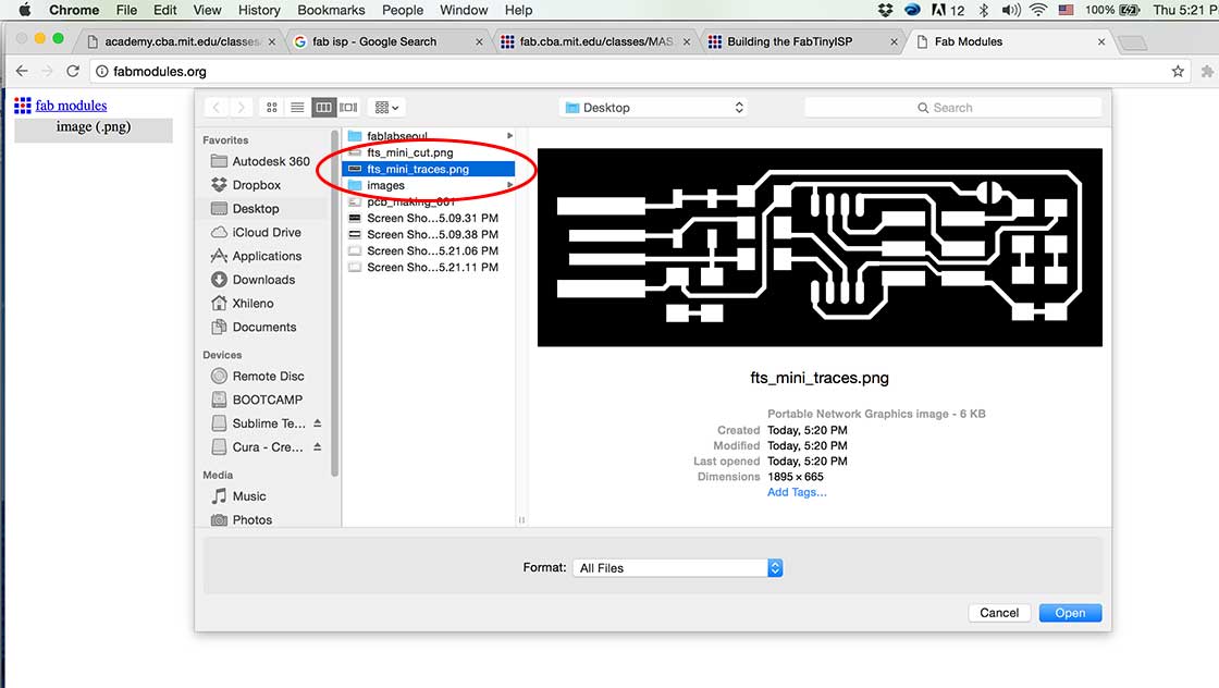
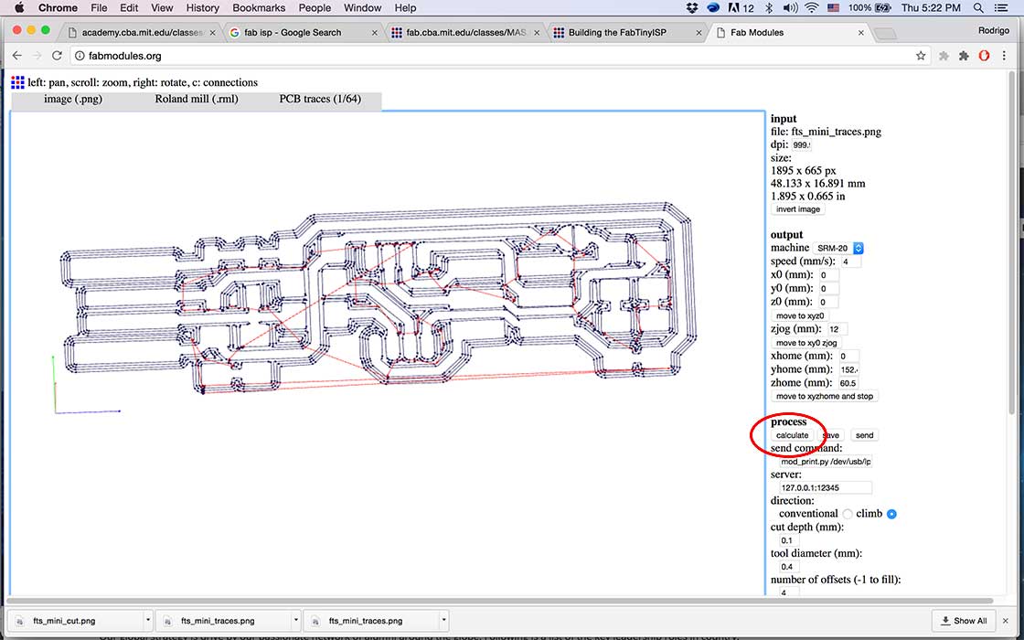
After deciding which ISP board to cut, I dowloaded the png files and imported them in fabmodules.org and made my gcode for the Roland SRM-20.
These are steps that I did to cut my board
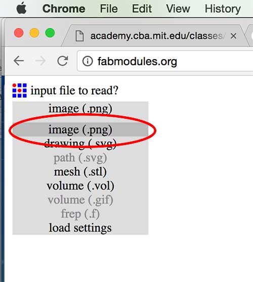
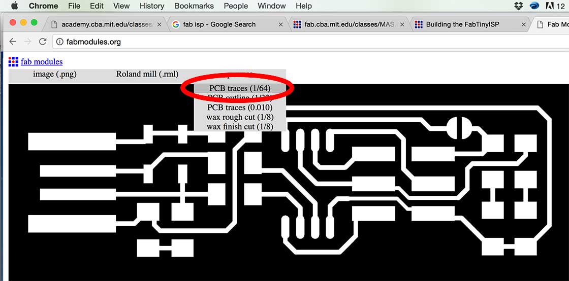
First you need to import/open the file, in this case I imported the png for the traces first. fabmodules.org was very easy to follow, as you see it gives you a lots of hints, first ask you the equipment you are using and then i ask you exactly which part of the board are you cutting (trace or outline) including the diameters of the mills. So, even if you are a noob at this, is easy to make the file (at least for this part) Before you calculate the tool path you need to set up few more things.
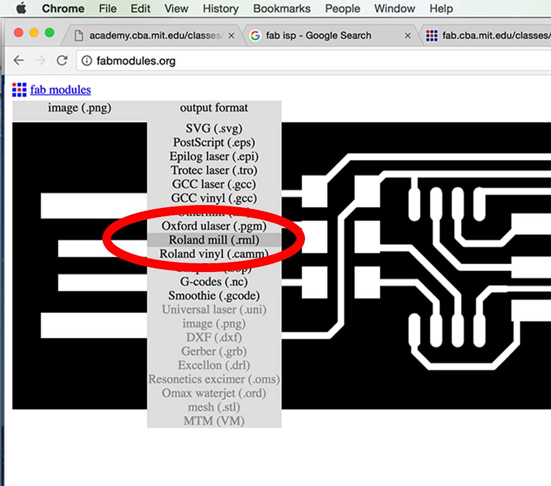
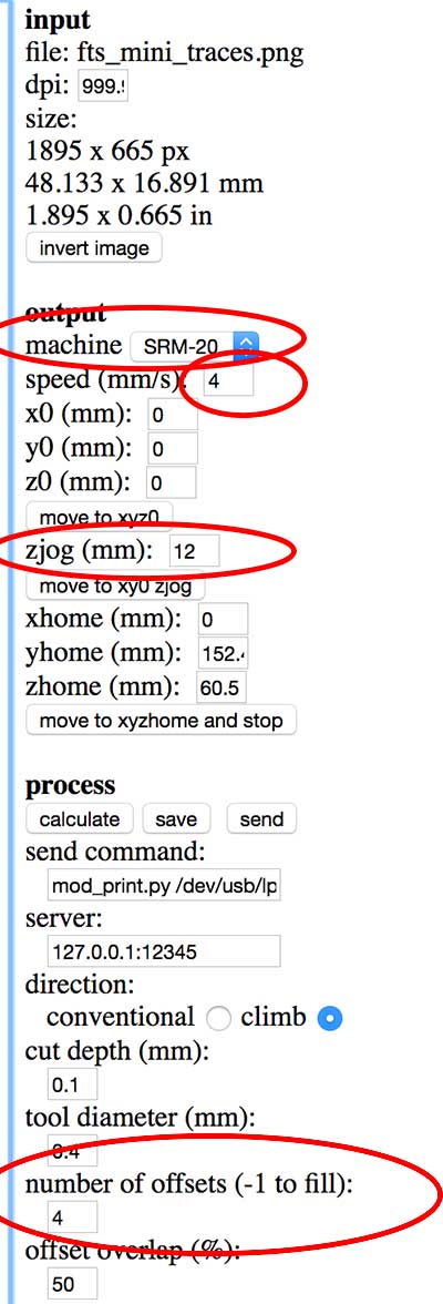
1. In "OUTPUT" you need to use the equipment of your lab
2. speed as "4mm/s" (if new mill "3 mm/s" is recommended)
3. zjog = represents how much the z will go up (in my case 12mm) to move to the next cut, this is to avoid hitting any obtacle and breaking the mill.
4. Number of offsets (-1 to fill): "4", this is to generate an space between lines to avoid circuits cut.
Once you are done with the setting you can press "calculate" to generate the tool's path (how the mill will move to cut the trace)
Note:For cutting the outline of the board I used the same steps, however, since I used a different size mill
(1/32) I adjusted the settings when creating the gcode by choosing the corresponding mill, changing the speed setting to "0.4mm/s" and letting the others settings untouched (number of offsets to "1").
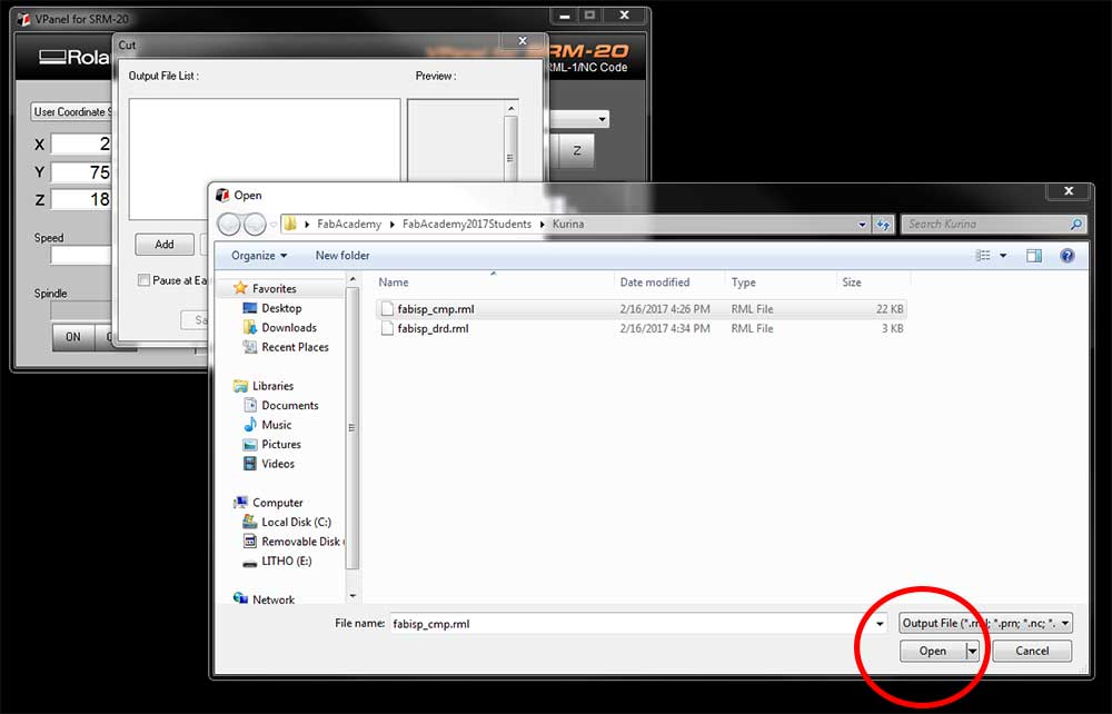
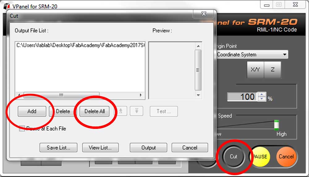
Once you have the DXF file you can bringing it to the CNC interphase software.
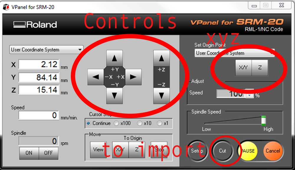
using the control panel you can move the nmill to set up the origin XY and Z independently from each other, after that press cut to import the ".rml" files. (remember to delete all previous files) Once you add that file press Output and the spindell should start working.
3. CUTTING AND SOLDERING THE ISP BOARD
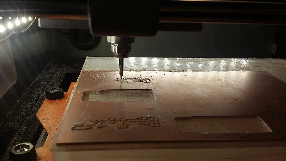
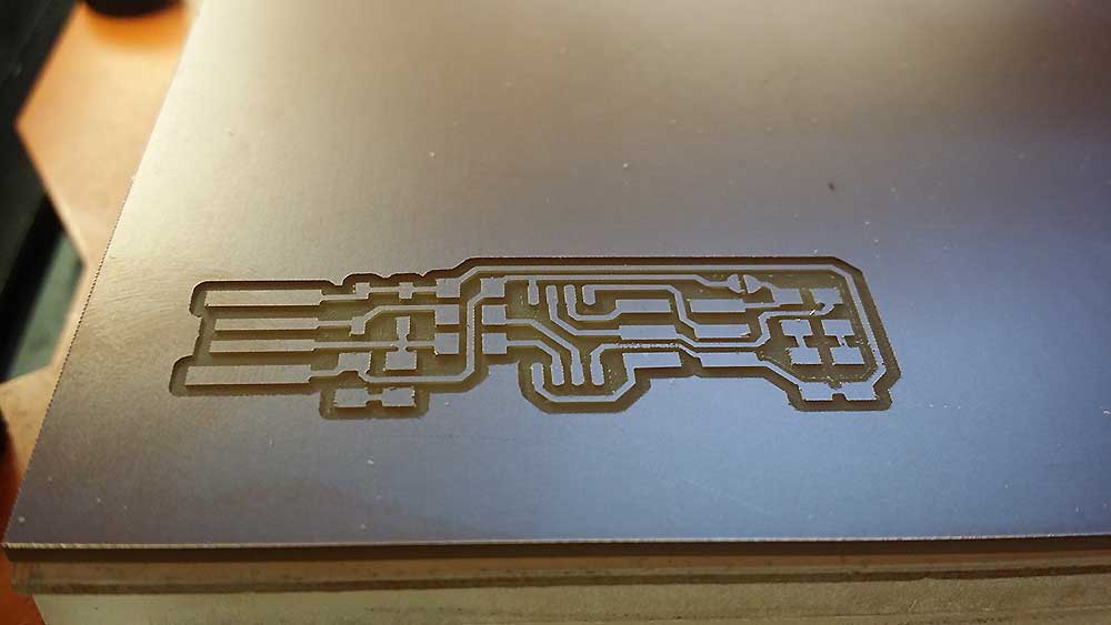
Once you have finish setting all the steps above, you can just enjoy the magic of Computer Numerical Control equipment.
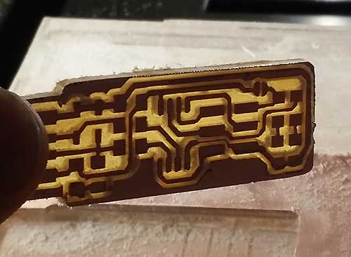
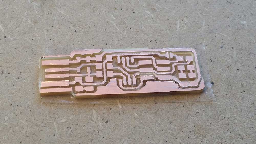
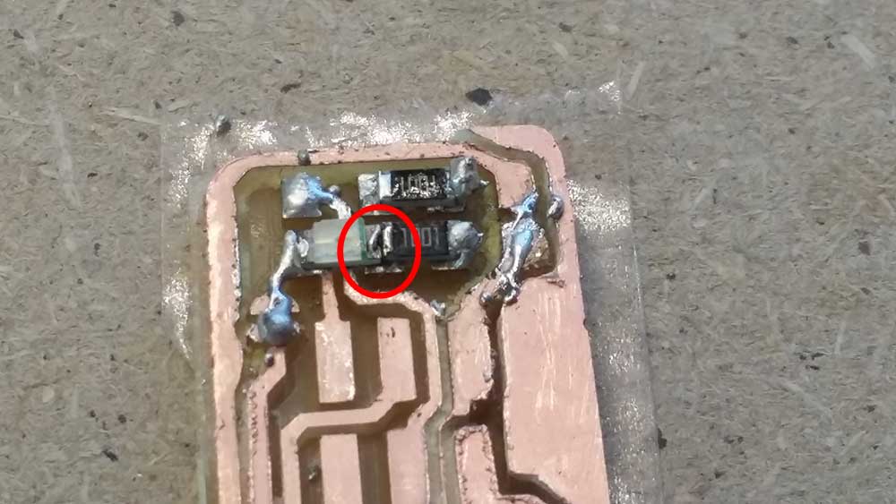
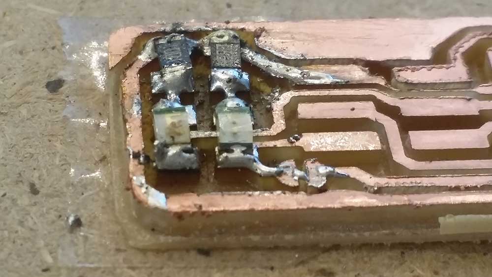
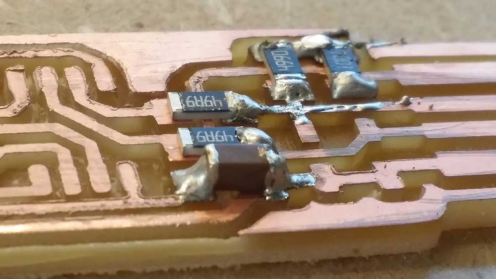
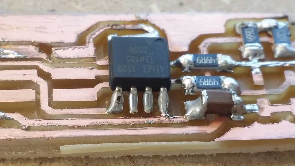
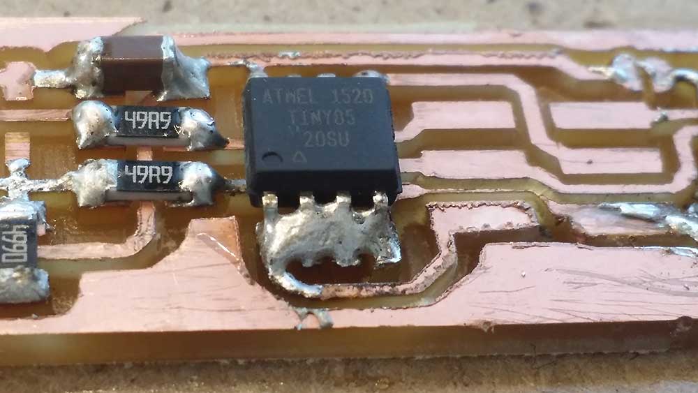
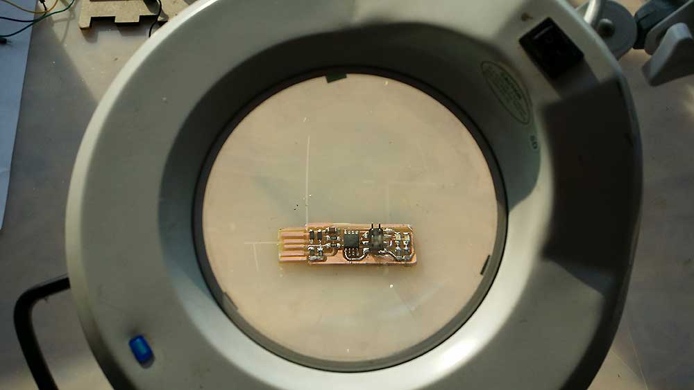
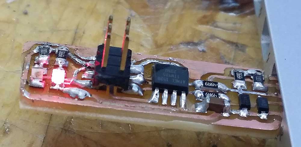
Short video doing the cut Once I cut the board, I realize that my cut was too deep, and since is my first cut, so I just kep going anyway . Shopping has never been so painful. I have soldered before but then all of a sudden is was too difficult, So, I said to myself "this can't be that hard", and the problem was that I solderthem together without respecting the resistor's personal space. This was so frustrating at first and I just end up de-soldering everything and doing it again. So, now really looks like y first board ever. As you can see in the pictures above I was getting better at this, at least looks cleaner. I remember a video that our instructor showed to us how to solder surface mount devices and they use a technique wheres is use a lot of solder and then is remove with the solder sucker.(more difficult then do one by one), However, everything looks better in a magnifying glass Red LED on, means that I successfully made the board with no shorts and now I can "try" to program it.
4. PROGRAMING THE ISP BOARD
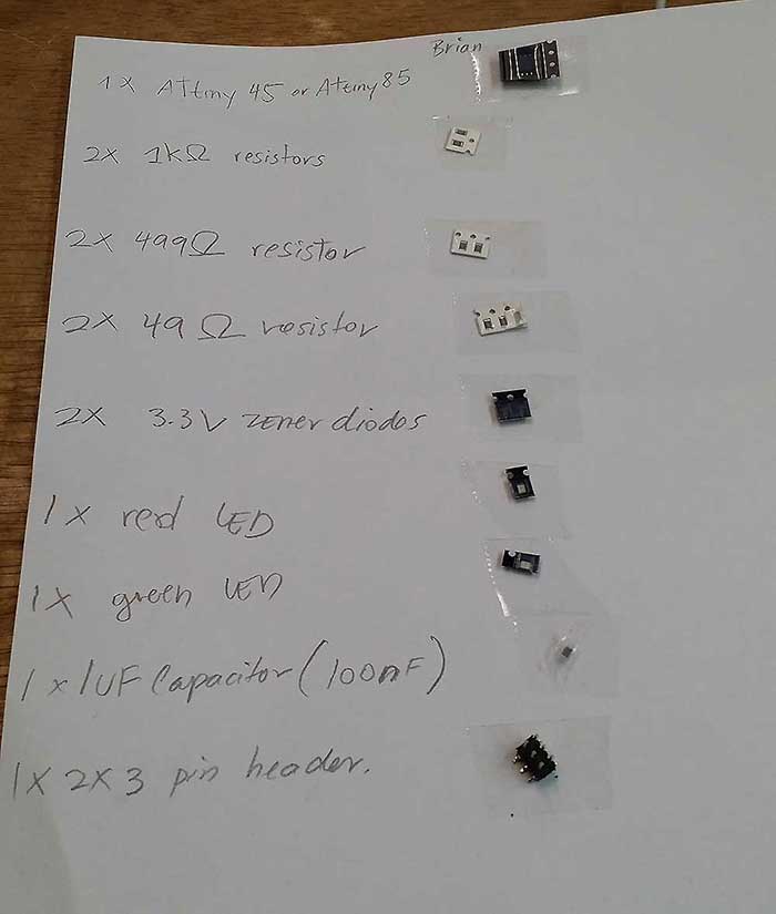
For the programing I followed Brian's instructions, below you can see the steps for Mac users.
1. Set up a development environment by dowloading CrossPack and Xcode. (DO NOT continue untill you have these programs intalled in you computer)
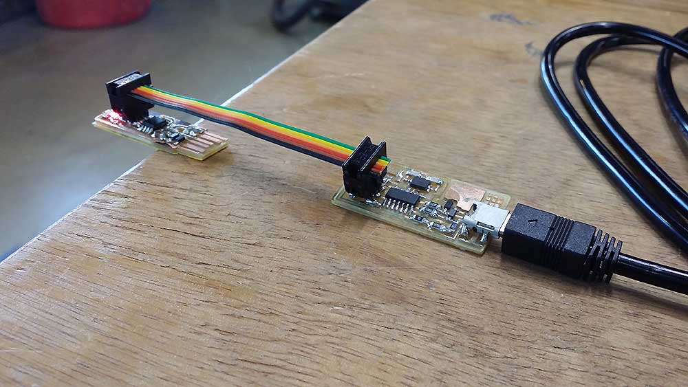
3. Unzip the file, open you terminal and "cd" in to the firmware folder and connect your board using your instructor's ISP.
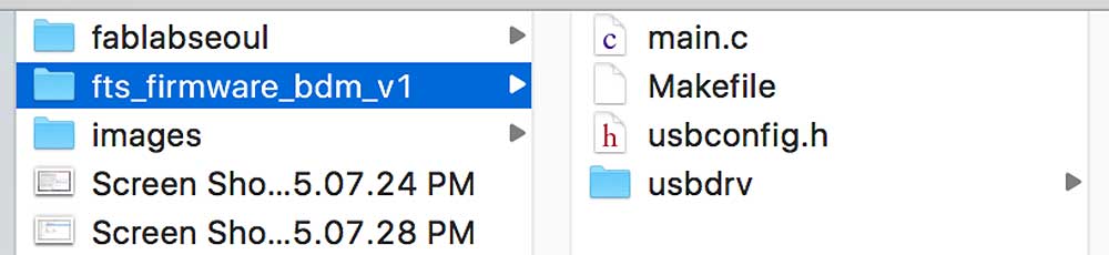
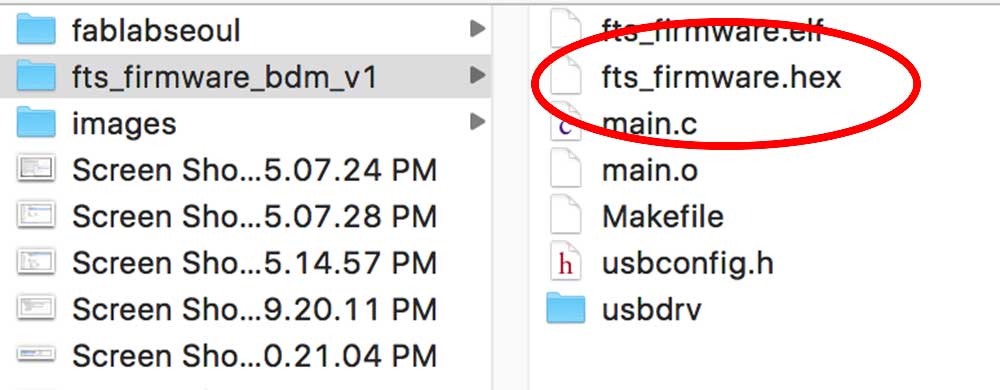
4. you should have something like in the picture below, right click in "Makefile" and open it in your text editor.
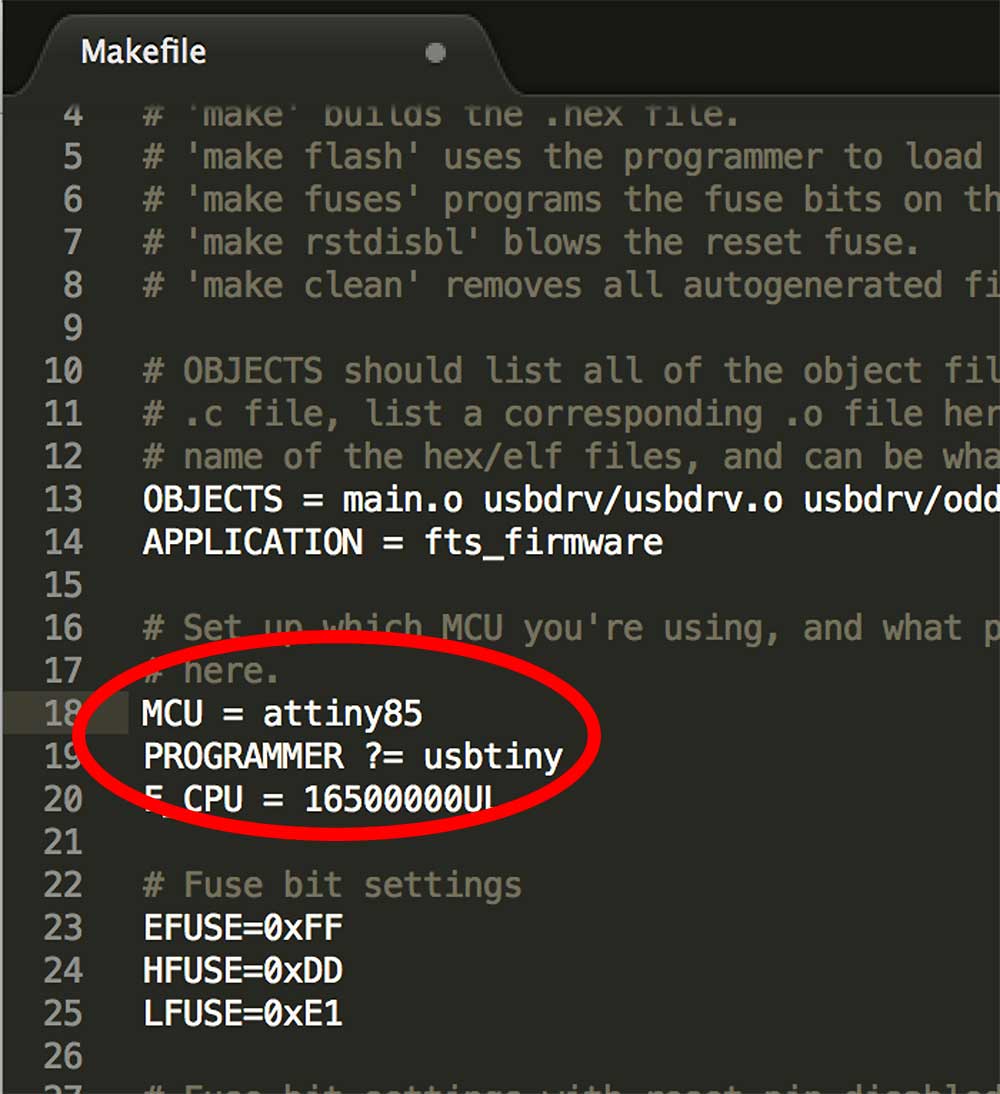
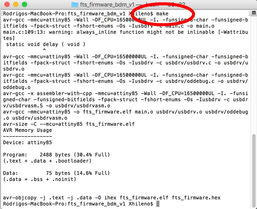
5. Edit the MCU (attiny 45 or 85) with the board you used, in my case I change from 45 to 85 and then make the ".hex" file by using the command "make". (if you are NOT using your instructor's ISP the "PROGRAMMER ?= usbtiny" Line should be changed, so go back to Brian's page to check how to do it.
and you should have a new file ".hex"
6. Once you have the "fts_firmware.hex" file, you can go back to the terminal and use the "make flash" command, this will program its flash memory with the contents of the ".hex" and after you need to run "make fuses", -This will set up all of the fuses except the one that disables the reset pin- (Acording to Brian's page)
Congrats to myself I have just made my very own first ISP board
To be continue...
Lessons Learnt
What I was not able to do this week:
Make a different board
program a board using my ISP board
breaking and endmill to have a souvenir from the lab