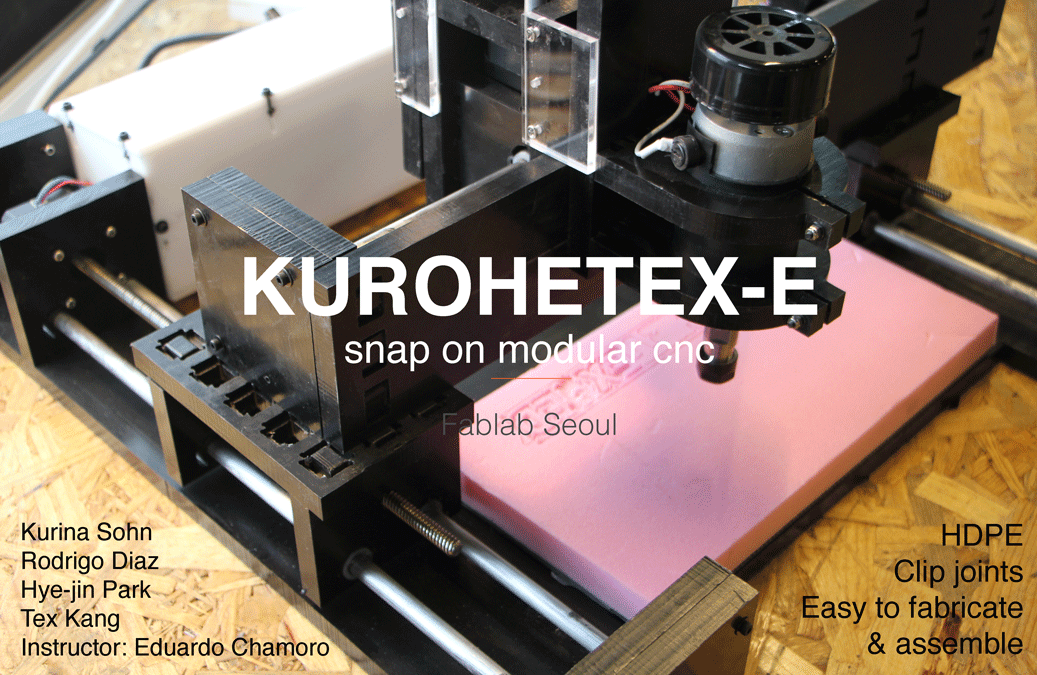
TEAM: KuRoHeTex-Ed
We decided to make our own CNC machine since we already had router spindle motor, and all the other materials ready.
Non-modular machine:
None of us had experience in machine design and engineering. We spent first week on basic understanding in machine and mechanism. As a group, we evaluated and came up with pros and cons about our design, and tested materials and joints.
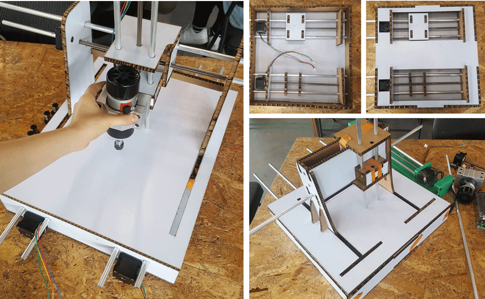
Back to Modular machine: We were persuaded by the advantages of modular design, and so we started to look back to last year’s project which was modular and thought, “what would we do differently/improve?”
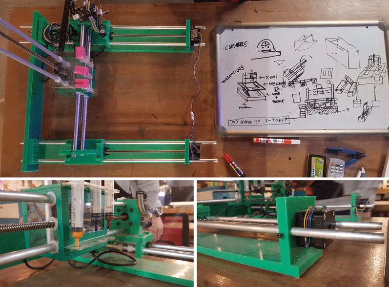
Machine & Mechanical Design
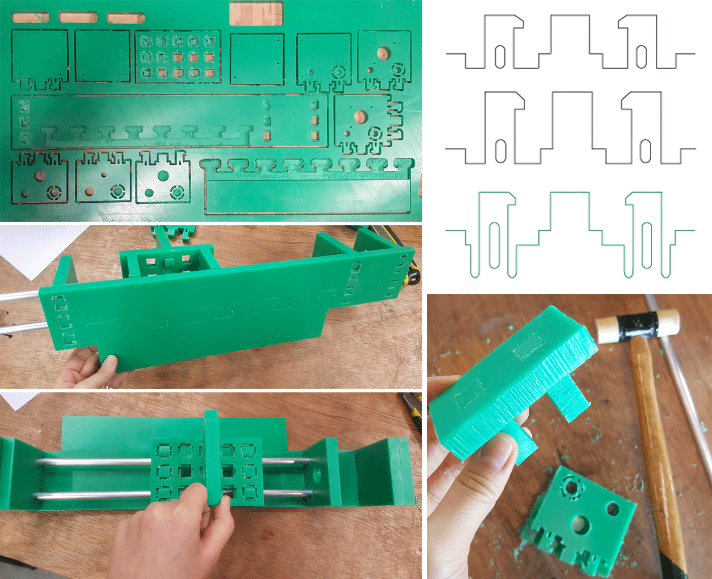
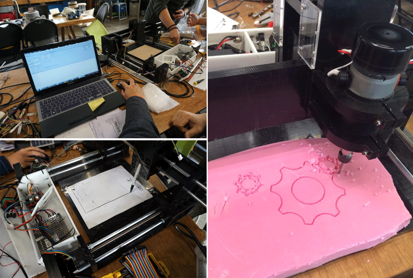
Testing HDPE, joints, and CNC.
(CNC Settings with green HDPE: 3mm upcut 1 flute endmill, RPM 16000/Feed Rate 140, cut depth=12.7 for green one (for testing), 13.7 for black one since the thickness of black one is 13mm compared to the green that was 12mm)
Materials:
HDPE(high density polyethylene), Fab MTM kit (1xCNC router spindle motor with control power supply, 4xstepper motor (NEMA 17) with 300mm leadscrew, 8xshafts (anodized tubes), 16xnylon bushing, 1xArduino CNC Shield version3, 1xArduino uno, 4xStepstick A4988 stepper motor driver carrier).
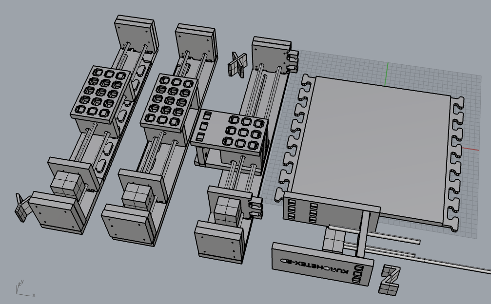
The distinguishing features (some improvements and some improvisations):
- 1. Joint for the bed
- 2. Connecting joint between modules
- 3. Arc shape cutting around one of the holes for shafts - to parallelize two shafts. Also the offset position of lead screw relative to shafts - to stabilize the machine
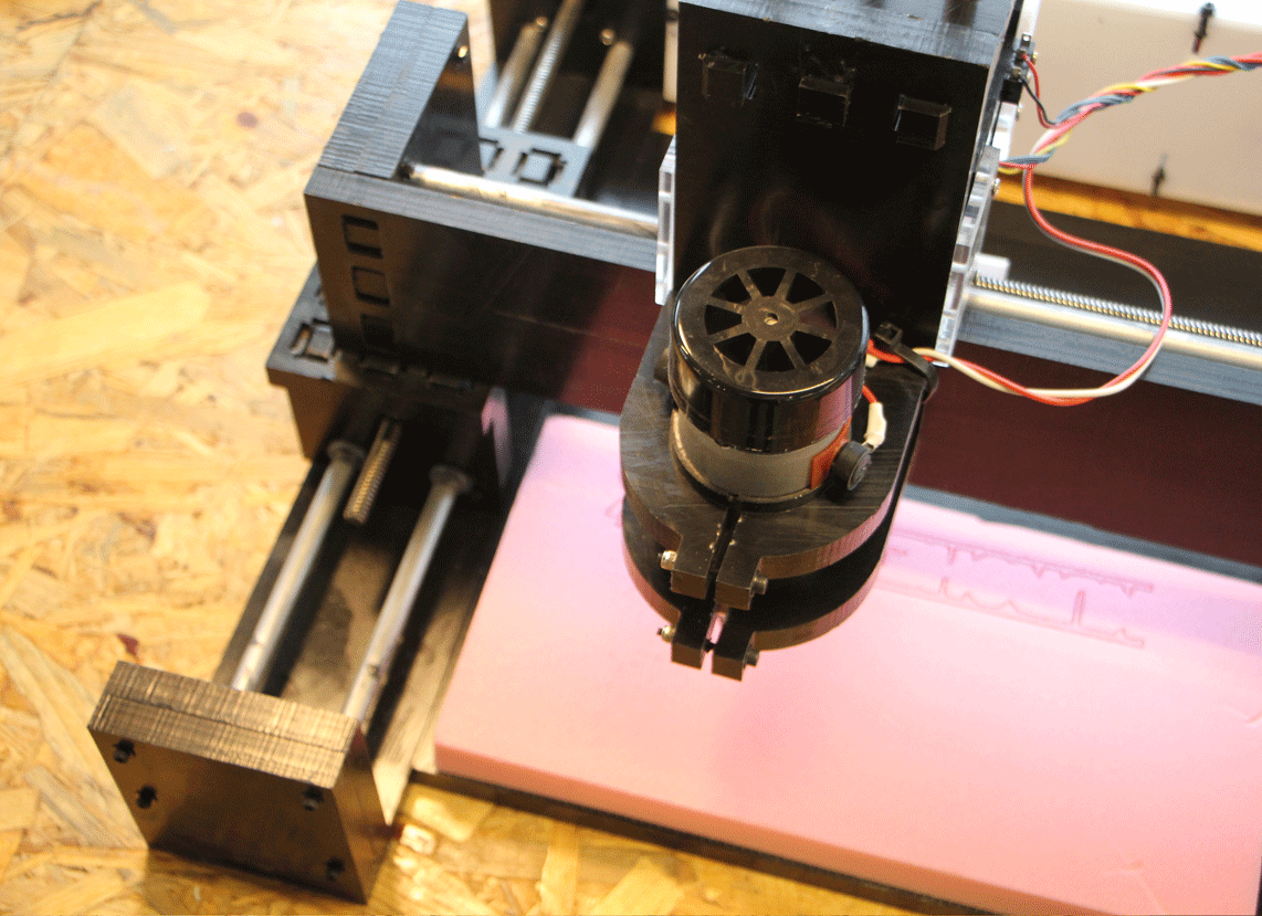
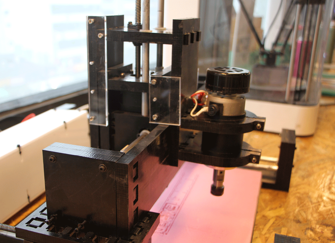
- 4. We reversed the front and back to make Z axis stronger by balancing the stepper motor and router motor. We also added extra supporting frames for z axis: to get stability, we sacrifice frictionless movement.
- 5. Router spindle motor holder with joint=keep the surface flat (no screw head), and reduce friction for z axis movement.
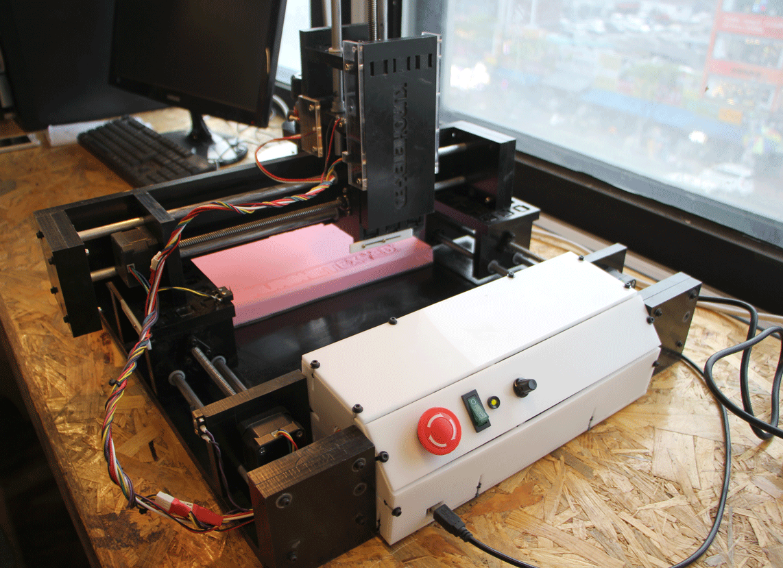
- 6. To prevent the machine from going beyond the limit, we attached switches for end stop function.
- 7. Controller box: we added a emergency stop button for both step motor (connected to end stop pin), router spindle motor and LED to show the power is on.
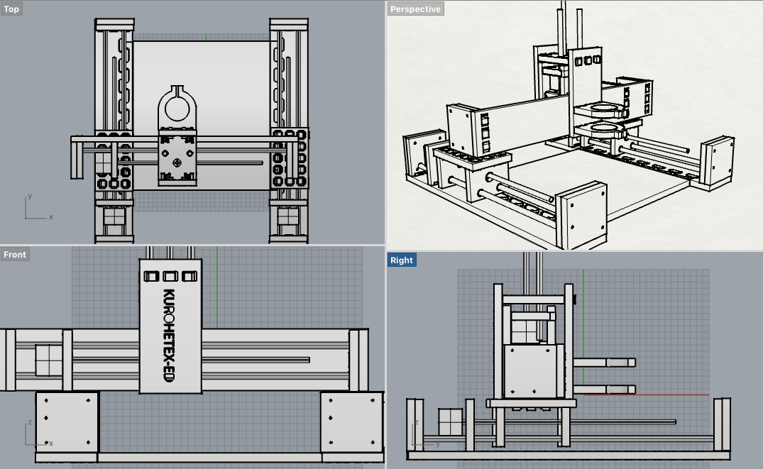
Mechanical Engineering
Errors...and fix them:
- 1. We ordered 12mm HDPE, but 13mm HDPE was delivered. We cut it with the same setting as green one, and it didn’t cut properly, and also joint didn’t fit. We should have checked the thickness more carefully.
- 2. Bottom plate= it didn’t fit, too much tension so it lifted up a little. It was alright with offset 0.3mm.
- 3. Z axis=
a. Making it all modular: failed, because motors were unstable.
b. New z axis design: failed, too wobbly. Few adjusted designs.
- 4. In programming=
a. We got only simultaneous movements in x, y, and z axes,
b. coupling second y axis with the first one failed.
Software Programming
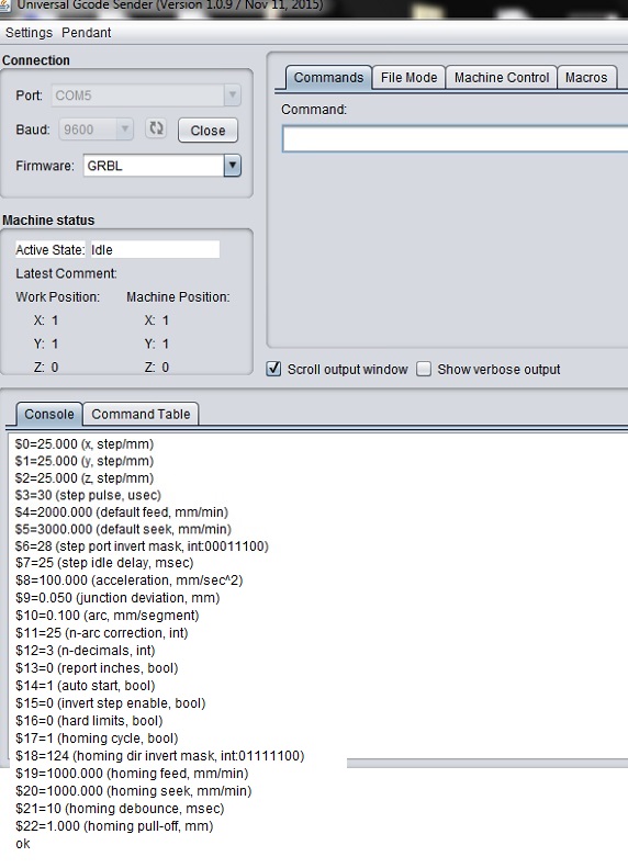
GRBL and Universal Gcode Sender
- We used an Arduino Uno with a Arduino CNC shield with 4 stepper drivers for the NEMA 17 stepper motors, with future plans to switch out the Arduino with a Satshakit.

- We flashed an opensource GRBL 0.8c hex file onto the Arduino using bootloading/avrdude and assembled/connected the board to the machine and its components. Some notable obstacles we encountered were fixing the wiring for the motors(to regulate the correct voltage), identifying that one of the stepper drivers was faulty and cloning the y-axis, adding physical limit levers as stops, adding an LED and an emergency stop button(connected to motors and arduino) for safety and convinience.

- Using Universal Gcode Sender as an interface and Fabmodules to convert png or stl images into gcode we had a functional but not ideal machine. Further improvements were made such as settings the values for GRBL. Initially done by scientific and quantitative guestimation, we calculated acceptable values for each setting such as the steps per mm, feed rates, acceleration, etc. After the first values, we systematically adjusted the values until we got a smooth running machine.
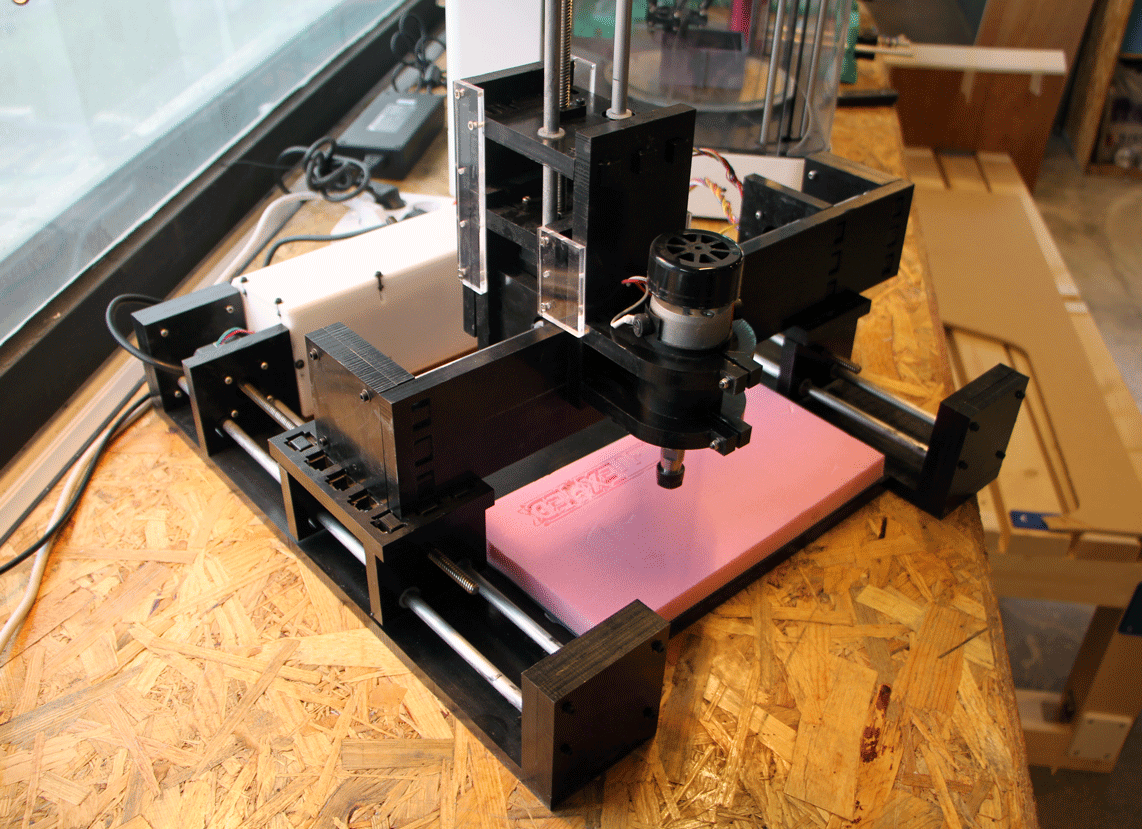
Testing the Machine
Introducing KuRoHeTex-Ed