Week 15: Networking and Communications
This week our task was to "design and build a wired and/or wireless network connecting at least two processors"
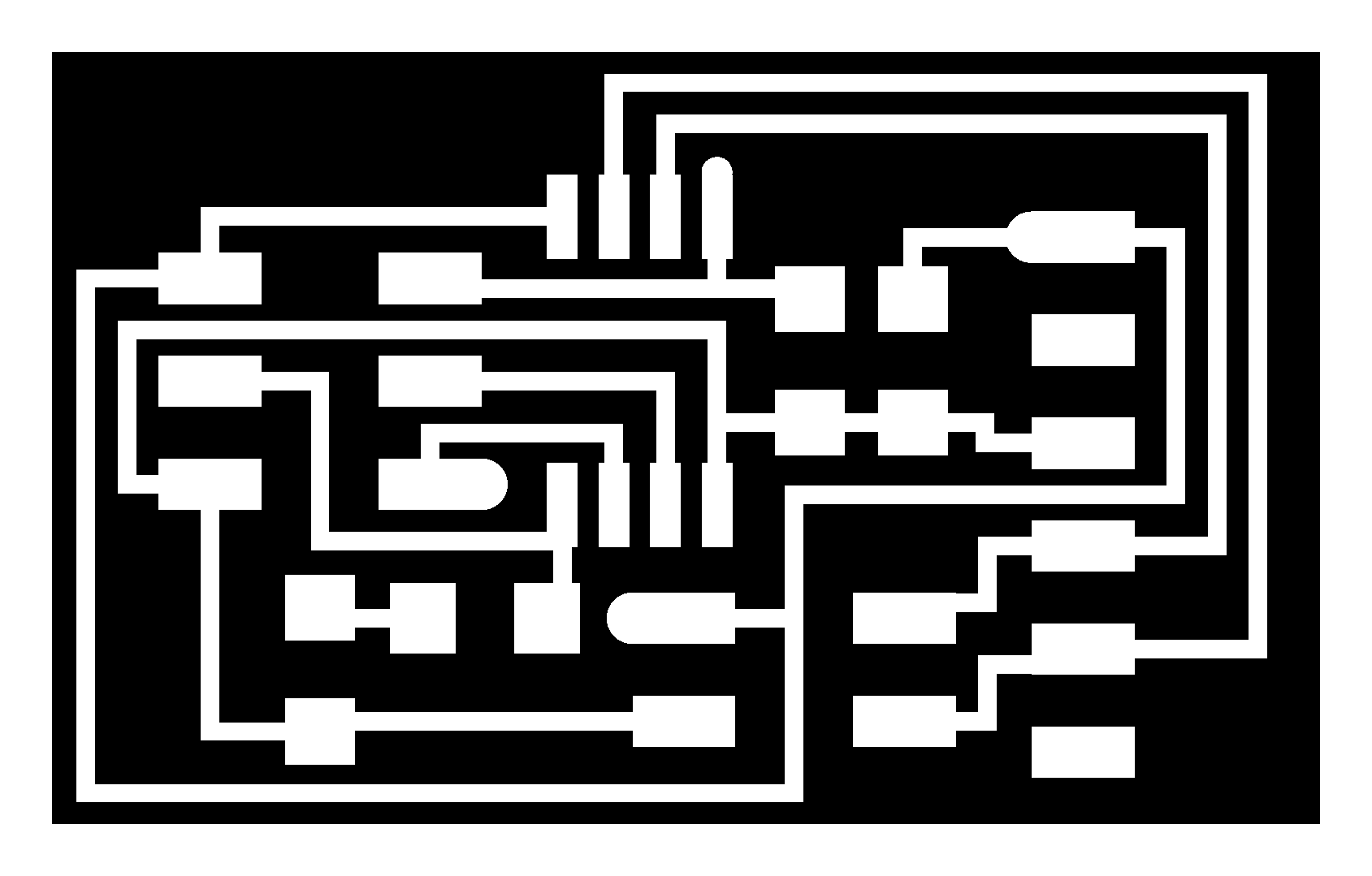
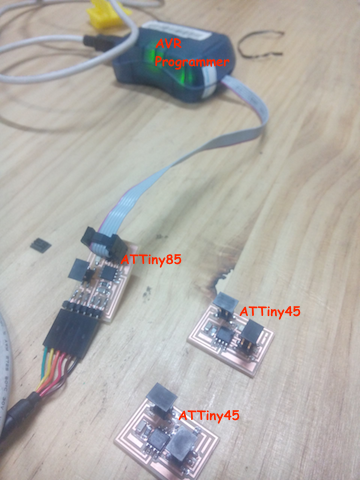
This was the goal, to create 3 boards that are networked and can talk to one another. Because my final project doesn't use networking, I used the board designs in the class tutorial in order to understand and learn the skills. Below is the files used to fabricate the boards.
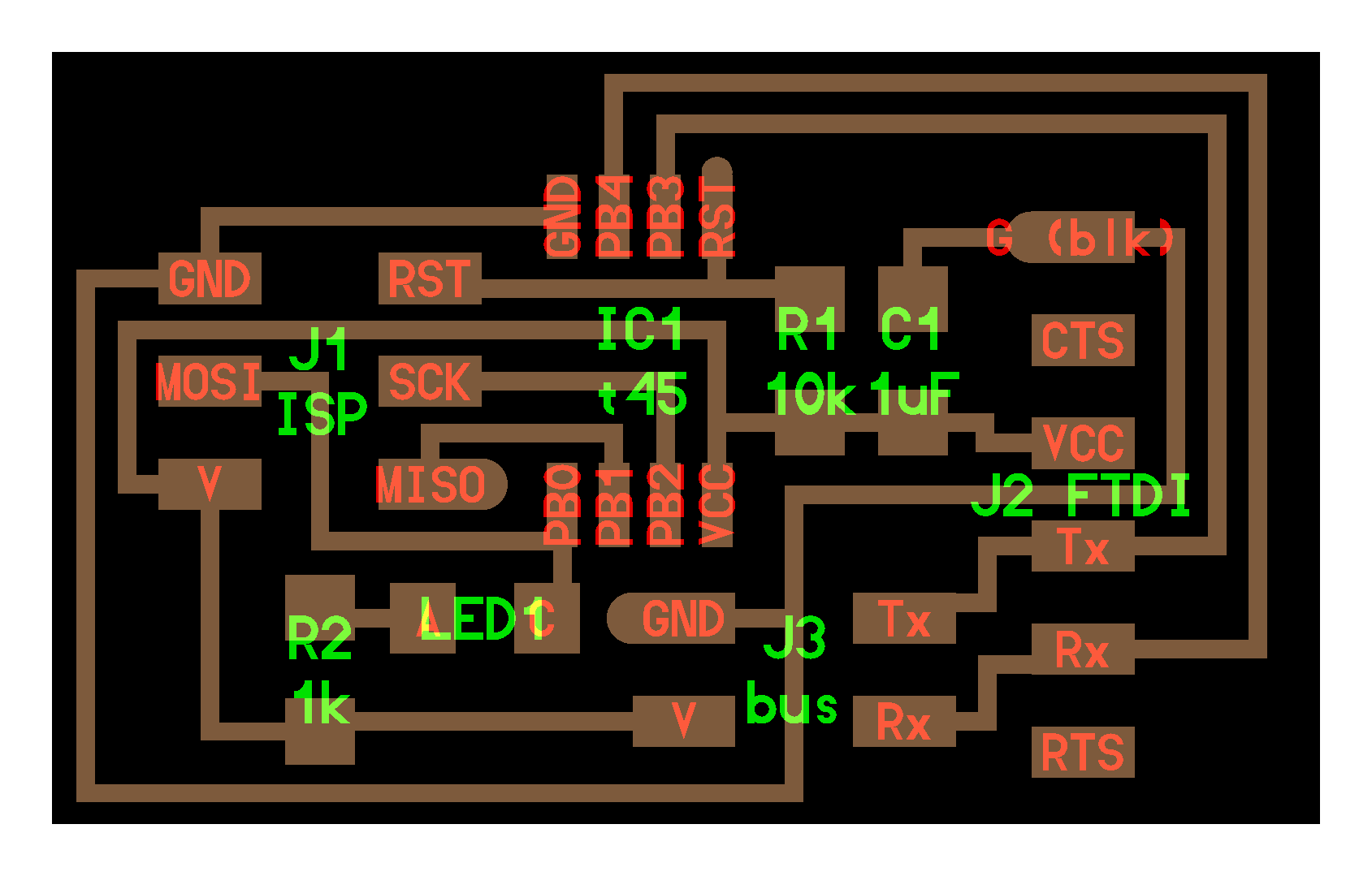
We used an ATTiny45 microcontroller on two of the boards, and an ATTiny85 microcontroller on the other. Both microcontrollers have the same datasheet and can be programmed the same.
This is a good tutorial that I followed.
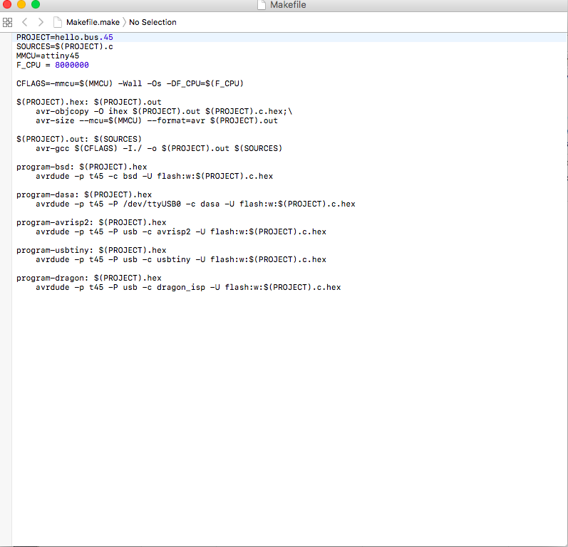
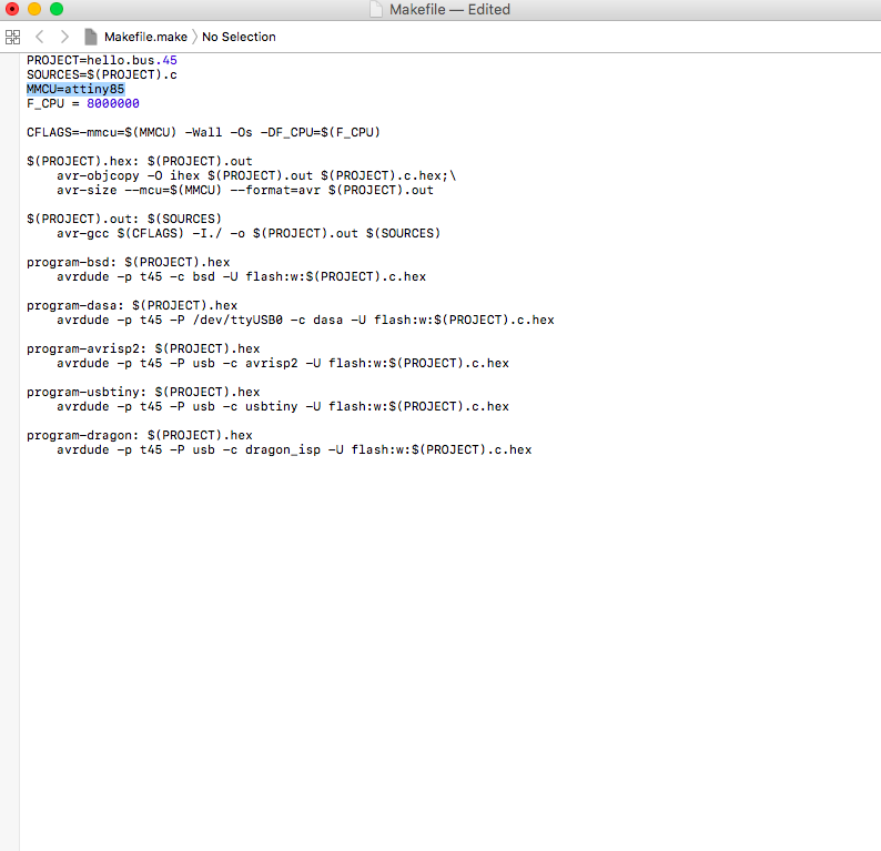
First I altered the make file in order to program the ATTiny85. This tutorial was useful in reviewing make files and the process of programming.
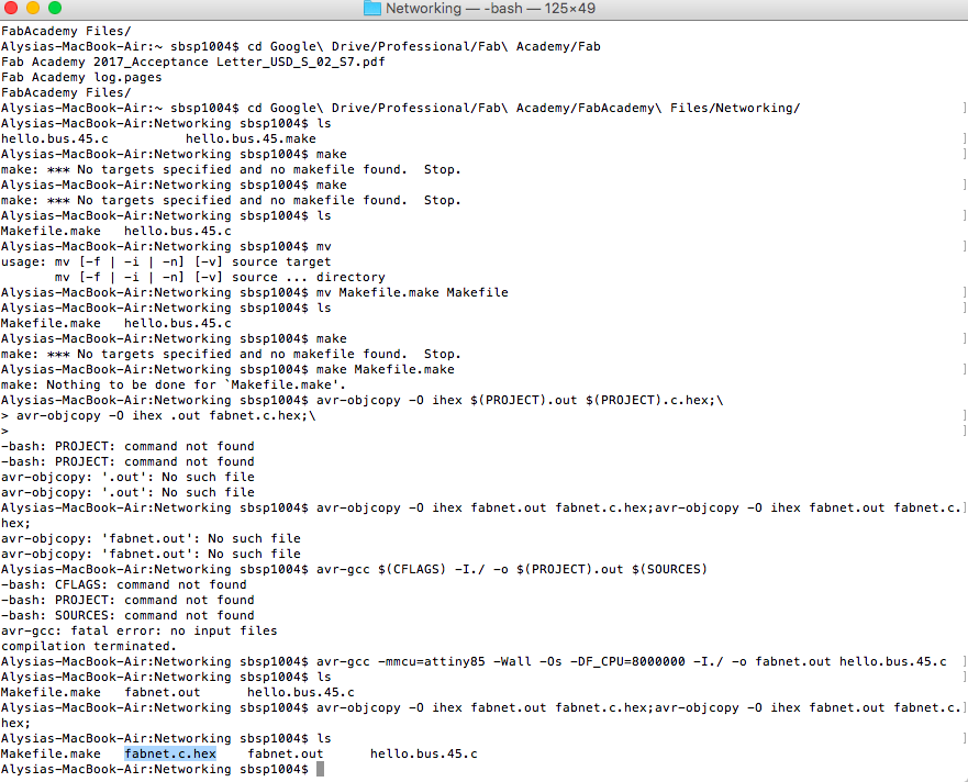
I then created the hex file. However, there was a problem with the AVR programmer, which required problem solving.
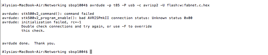
It turned out after a lot of problem solving, that there was a problem with one of the board chips. We reasoned it was beacuse of too much static during fabrication. So in making a new board (the bridge), I made sure to have an anti-static wrist band on. This time the bridge board worked well, and I could connect it to the other two little boards. The eagle files for the bridge board are found below.
Then I got on with the programming of the network. To begin with, in the code I assigned each board an ID number (0, 1, 2). This allows the computer to talk to the nodes with a specific ID attached, and when the node matches it's own ID with an incoming number, then it replies. Otherwise, the communication pin is 'floating' in an electrical sense. In the code, it is programmed to be in receiving mode which deactivates it so it doesn't interfere with any other communication on the line. This is key, as every board is on the same 'buss', or line.
I used a USB to RS232 FTDI chip arduino converter (the FTDI acts as a translator between the USB and RS 232 protocol). I learned this is appropriate for networking over short cable distances; if longer connections are required, the RD 485 protocol is better. This includes a buffer that reduces energy losses over the transmission lines, allowing the system to be connected over longer distances.
I called the nodes by ID from the terminal (viewable in the following video). Note that the code contains a delay, which requires the system to wait after an answer is given on the line. This is important to allow the lines to clear before another signal is sent.
Here are the files from this week:
Arduino code Hex file Node Board Node Board schematic Bridge Board Bridge Board schematic