Week 13: Input Devices
This week our task was to "measure something: add a sensor to a microcontroller board that you have designed and read it"
The steps I took for this week's assignment were:
- Experimented with materials acting as potentiometers using the board and speaker fabricated for the output devices assignment;
- Fabricated a new board specifically for reading input signals from the potentiometer-materials;
- Measured the changes in voltage by reading the signal from the board when experimenting with different materials.
The following shows part one, where I experimented with materials using the board and output speaker system fabricated for the Output devices assignment.
Then I closed the circuit using conductive plyers. An analog to digital moodule in the microcontroller transforms this signal as an input. A PWM module then converts this into a volume signal.

I then played with closing the circuit using various kinds of conductive materials. The variation in resistance levels in the materials translated into variation in sound from the speaker
I played with the sounds coming from the various materials, as shown in the video below.
Then came part 2, designing a board specifically for transforming the analog input signal resulting from variation in the resistance of materials used to close the circuit into a digital reading. We designed the board in Eagle: see below for the schematic and board views.


Then came the step of exporting an image and loading into the fab modules for cutting


I had to cut the board three times, as the pcb plate was a litte uneven. But finally, the result came out well:

Then came assembly of all the components. I used an ATtiny microcontroller (the pin out is found here), which includes an analog to digital converter (ADC) module necessary to transform the analog input to digital signal.
Here's a view of the assembled board:

Now came the code needed to read the input signal from the wires used to experiment with various resistances with conductive materials. The image below shows the code, with notes made to explain the various parts:

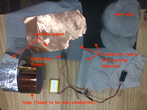
Below is a picture showing the board and materials used, as well as a video showing the experiments with conductive materials and resultant digital readings. To explain, the Analog to Digital Converter in the ATtiny core transforms the voltage drop (caused by the differences in resistance of the different materials), and transforms them into a digital output, the range of which (0 - 1023) is determined by the resolution of the microcontroller ADC (10 bits, where a base 2 raised to the power of 10 gives 1024 values. This explains the range from 0-1023 values that is the range of the signal read by the computer terminal as the digital signal value). As can be seen in the video, when the wires are in the air (no conductivity), the signal readout is 1023. By contrast, when the wires are touched to the highly conductive wire sponge, the voltage drop is reduced, with a read-out of 18 to 19.

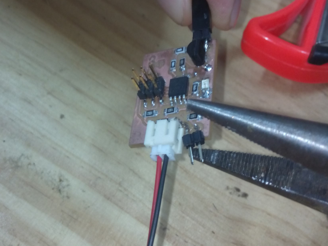
I learned that to transform this digital reading back into an analog reading (in volts), I could take the digital reading, devide it by the maximum digital range (1023 in this case), and multiply it by the reference value of the circuit (measured as 5.07 volts). We measured this - see the picture below. Note that both the 10 bit ADC and the max value of 5.5 operating voltage are specified in the ATtiny 45 datasheet.

Here is the file from this week:
Input Board filesBoard Schematic
Board Design
Board fabrication traces
Board fabrication holes drill
Board fabrication edge cut
Input board code