Assignment Week 4: Electronics Production
This week our task was to understand the basics of in-circuit programming. This included milling a printed circuit board and soldering components onto it
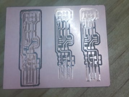
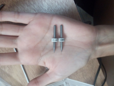
At first we ran into problems when milling the pcb for the FabTinyISP - our milling heads needed to be replaced (see image above)
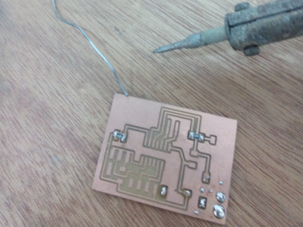
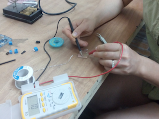
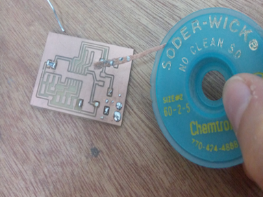
While waiting to get replacement heads for the milling machine, we started to learn soldering. First I practiced gettting the right amount of wire to stick to the pcb. Then, I soldered a resistor and tested the connection with the help of a multimeter. Finally, I practiced unsoldering the resistor and other drops of wire from the pcb using solder-wick.
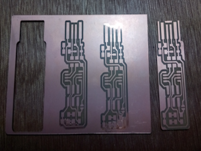
We got the replacement head (picture above on left). The first attempt failed because the pcb wasn't completely flat on the base in the machine. The second attempt suffered from the same problem, in addition to the x,y origin being a bit off. I fixed both of these problems, and it worked perfectly (picture above on right).
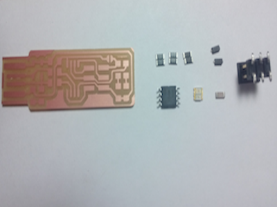
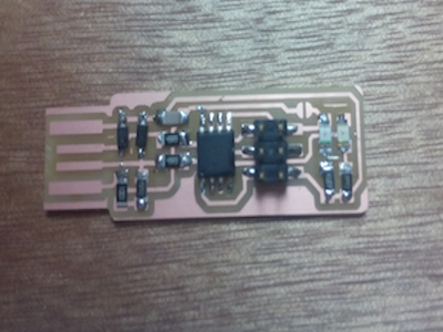
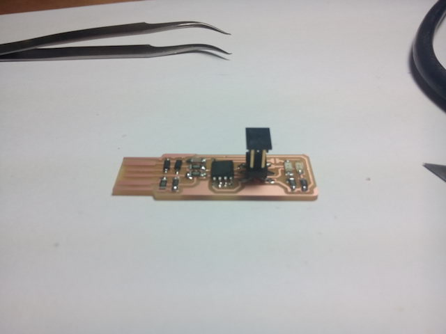
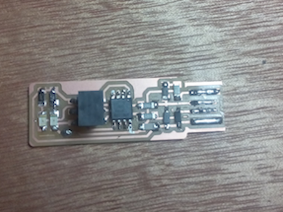
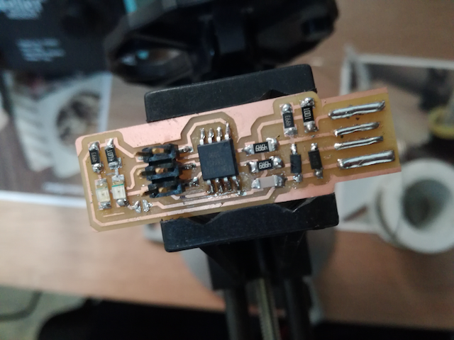
The pictures above show the steps I took to assemble the board. With my milled board I set out the specified parts (top left), and then soldered them onto the board (top right, bottom left). In order to better fit into the usb holder, I soldered some extra wire onto usb connectors (bottom right).
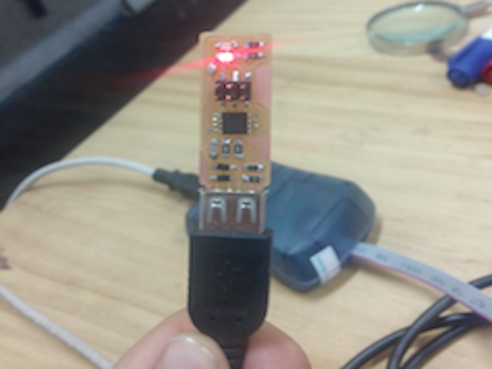
I then plugged the board into a usb port using an extension chord, and the red LED lit up!
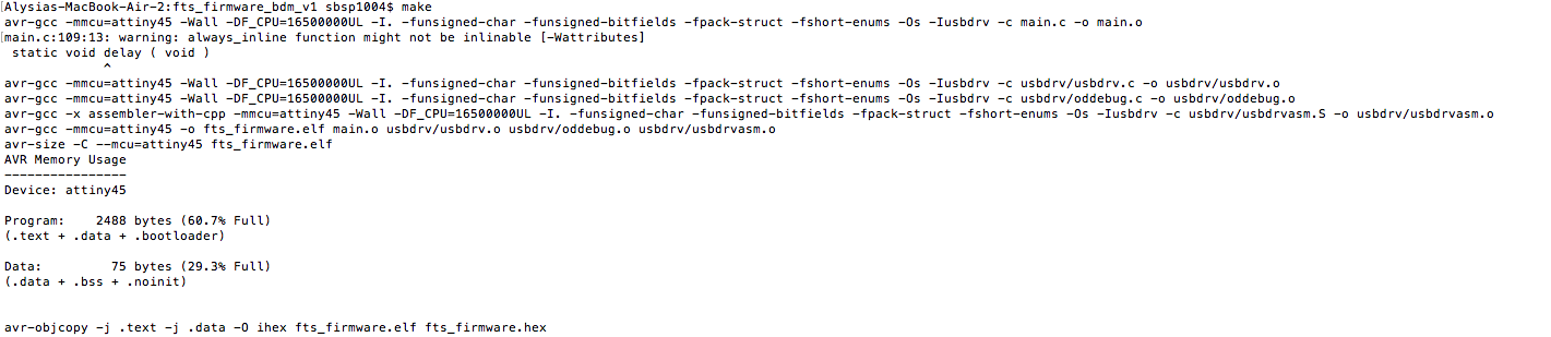
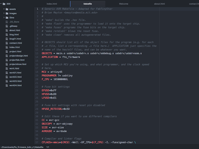
To program the board, I then downloaded CrossPack for mac (picture above), and downloaded the firmware source code "fts_firmware_bdm_v1.zip". I ran the 'make' command to build the hex file. This worked!
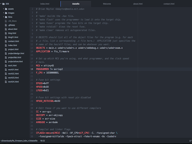
I then edited the make file, changing the programmer from usbtiny (picture left) to avrisp2 (picture right)
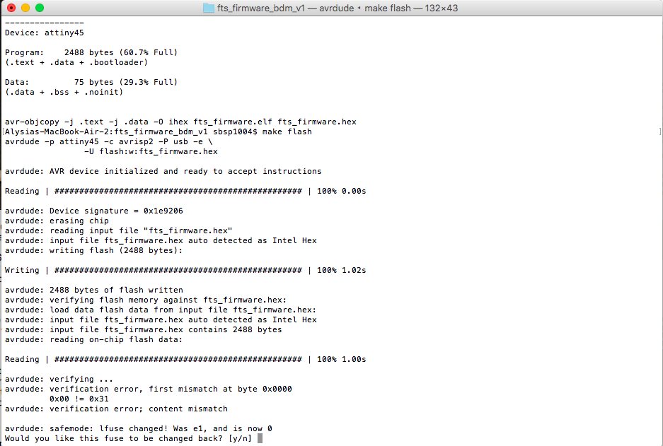
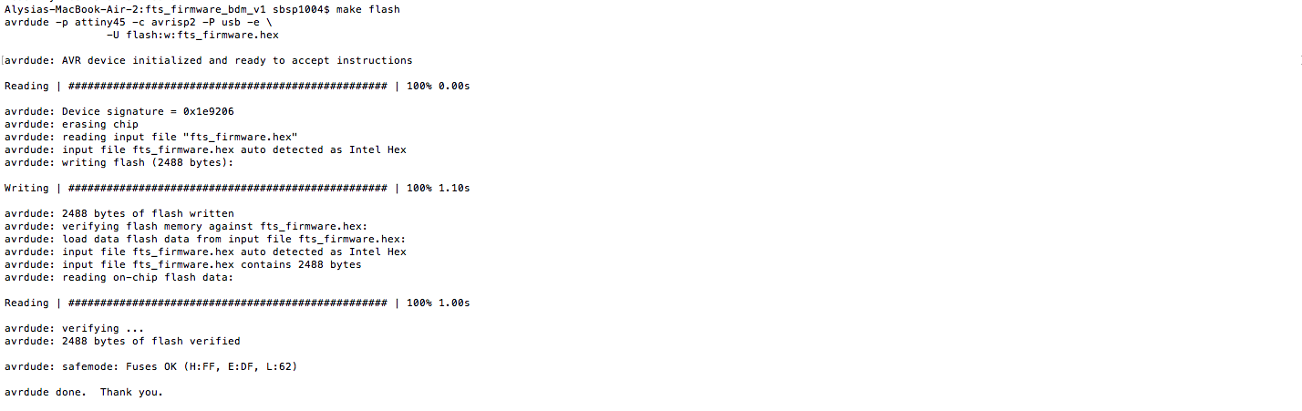
Then I ran 'make flash' to erase the chip and reprogram it with my hex file. At first, there was a problem, and we found it was a faulty chip. After desoldering and soldering a new one, it worked!
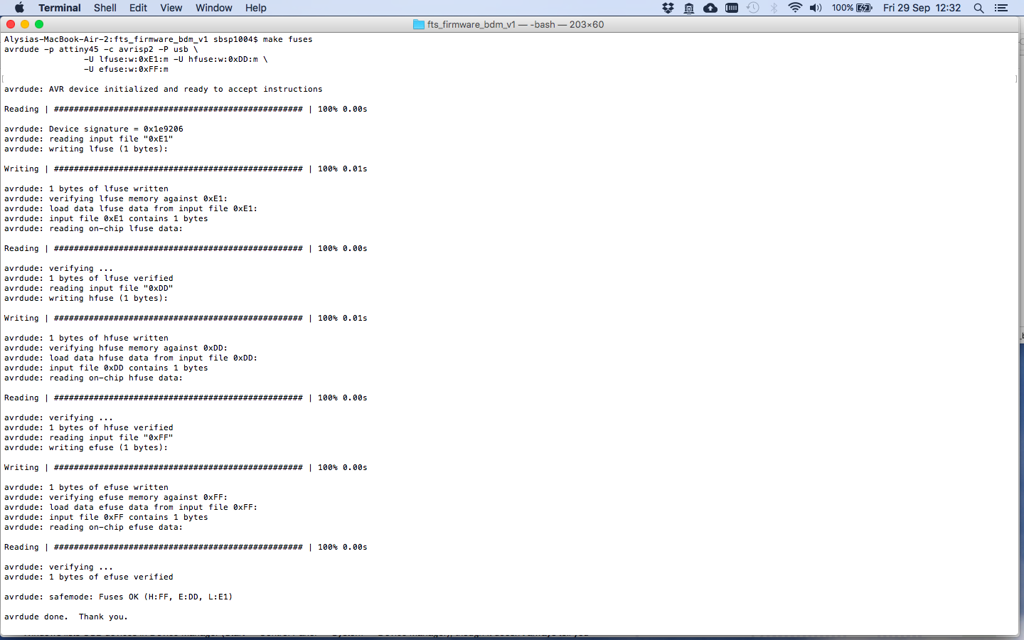
Now came time to 'set the configuration fuses'. This was done with the 'make fuses' which worked nicely.
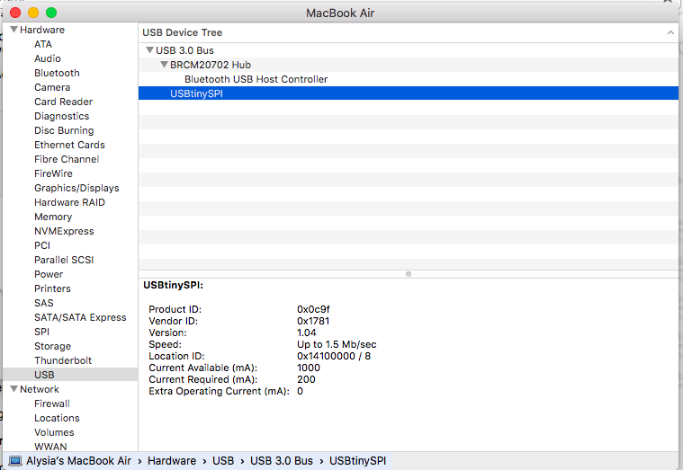
I checked my USB connection by opening up system preferences in my MAC, and looking under 'usb' in the system report. The screenshot below shows it being recognized.
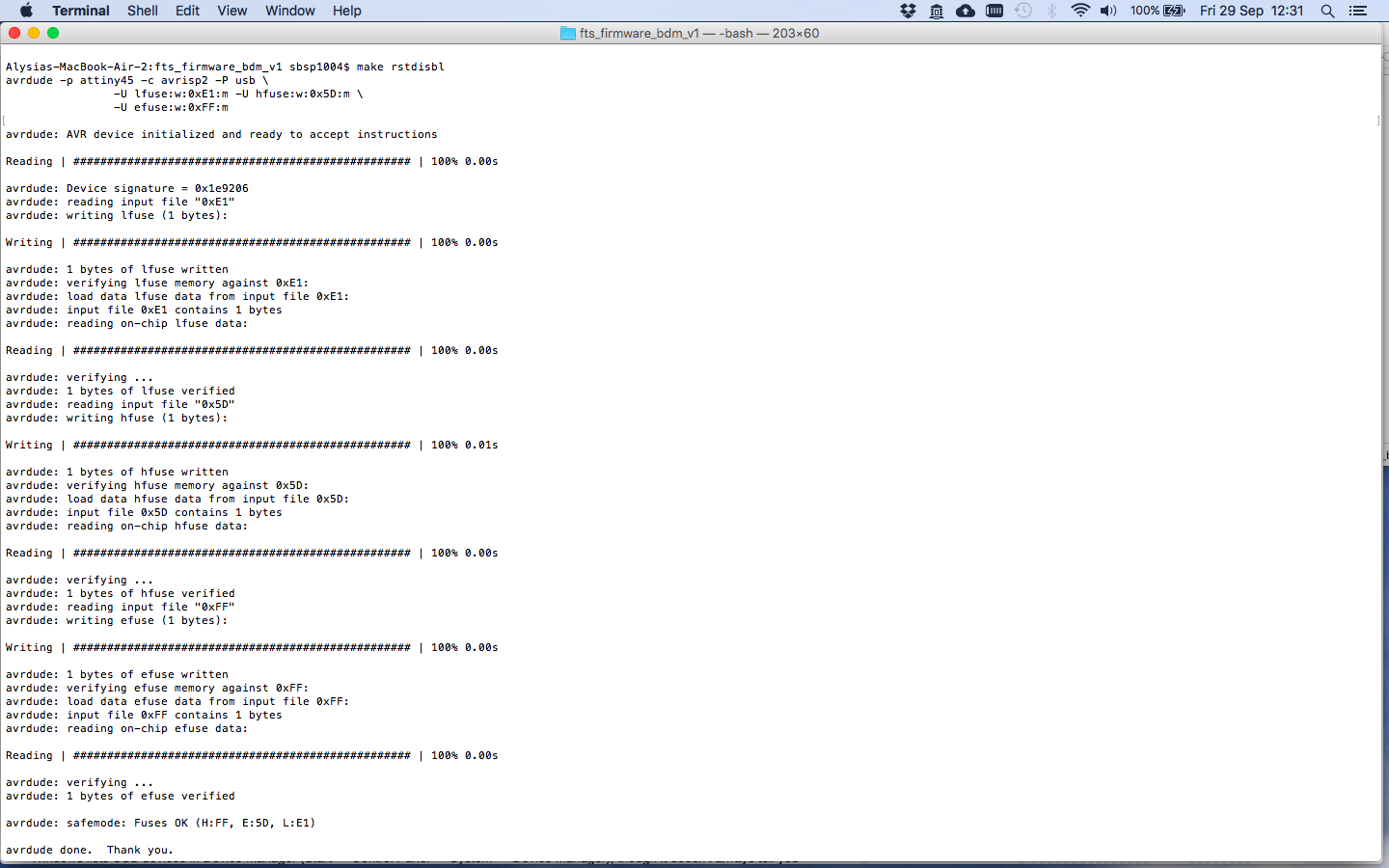
Then came the final steps to turn my board into a programmer board. I ran the command 'make rstdisbl' which reset the disable pin into a "GPIO pin" or General Input/Output pin. This is necessary to turn my board into a programmer, but it also means that it can no longer be reprogrammed by the avrdude.
As a final step, I desoldered the bridge on the solder jumper (see picture below). Now my FabTinyISP board was ready to be a programmer.
Here are the files from this week (sourced from this Fab Tutorial
Traces file
Cut file
Firmware source code
Hex file
Make file (modified)