OUTPUT DEVICES
- Demonstrate workflows used in circuit board design and fabrication
- Implement and interpret programming protocols
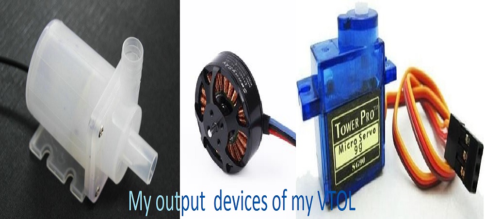
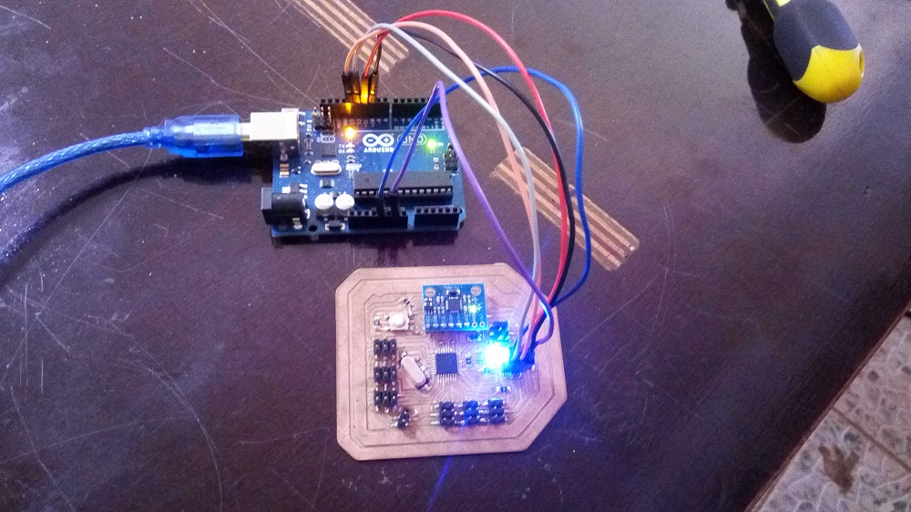
As i said I decided to organize the two exercise "input" and "output" and my project controller together, to make a board I will use in a project.This week I'll try to look on how i can intregrate gyro stablilization for horizontal,using atmega 328p, MPU 6050 (gyroscope and ACCELEROMETER) and the other pin i will let them connected to pin header for preview layout of my flighter controller so that i can ready the value RC receiver
Board Design
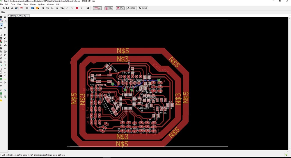
Download Boards files
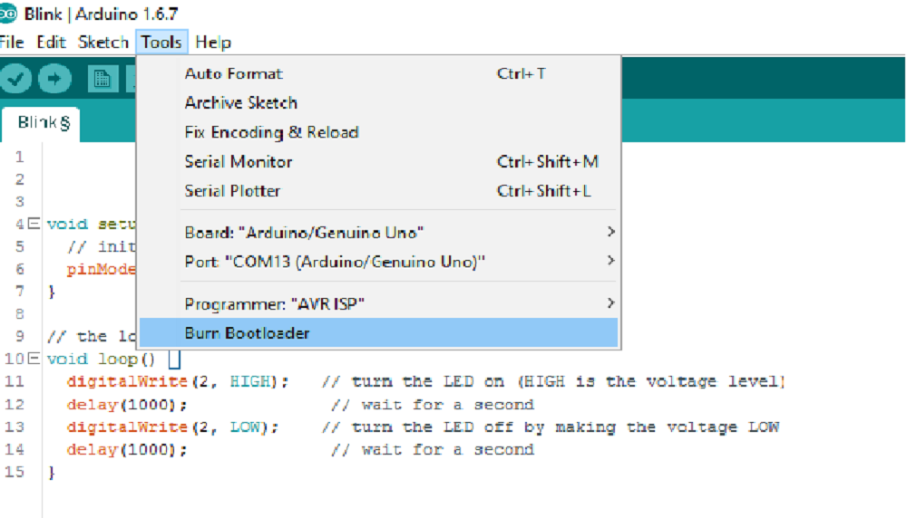
BURNING BOOTLOADER ON THE CHIP

Working with servos
after reading the values of the i have to write the calculated pitch and roll on my two seros attached on A1 and A2 of my flight controller, to do that i used the following code:#include#include "I2Cdev.h" #include "MPU6050_6Axis_MotionApps20.h" //#include "MPU6050.h" // not necessary if using MotionApps include file #if I2CDEV_IMPLEMENTATION == I2CDEV_ARDUINO_WIRE #include "Wire.h" #endif #define LED_PIN A0 bool blinkState = true; Servo Servo1; // First Servo off the chassis Servo Servo2; // Second Servo off the chassis int Servo1Pos = 0; int Servo2Pos = 0; float mpuPitch = 0; float mpuRoll = 0; float mpuYaw = 0; // define MPU instance MPU6050 mpu; // class default I2C address is 0x68; specific I2C addresses may be passed as a parameter here // MPU control/status vars uint8_t mpuIntStatus; // holds actual interrupt status byte from MPU uint8_t devStatus; // return status after each device operation (0 = success, !0 = error) uint16_t packetSize; // expected DMP packet size (default is 42 bytes) uint16_t fifoCount; // count of all bytes currently in FIFO uint8_t fifoBuffer[64]; // FIFO storage buffer // orientation/motion vars Quaternion q; // [w, x, y, z] quaternion container VectorInt16 aa; // [x, y, z] accel sensor measurements VectorInt16 aaReal; // [x, y, z] gravity-free accel sensor measurements VectorInt16 aaWorld; // [x, y, z] world-frame accel sensor measurements VectorFloat gravity; // [x, y, z] gravity vector float ypr[3]; // [yaw, pitch, roll] yaw/pitch/roll container and gravity vector // relative ypr[x] usage based on sensor orientation when mounted, e.g. ypr[PITCH] #define PITCH 1 // defines the position within ypr[x] variable for PITCH; may vary due to sensor orientation when mounted #define ROLL 2 // defines the position within ypr[x] variable for ROLL; may vary due to sensor orientation when mounted #define YAW 0 // defines the position within ypr[x] variable for YAW; may vary due to sensor orientation when mounted void setup() { Servo1.attach(A0); // attaches the servo on A0 to the servo object Servo2.attach(A1); // Second servo on A1 delay(50); Servo1.write(0); // These are command checks to see if the servos work and Servo2.write(60); // to help w/ the initial installation. delay(500); // Make sure these movements are clear from the rest of the chassis. Servo1.write(180); Servo2.write(120); delay(500); Servo1.write(0); Servo2.write(90); delay(500); // join I2C bus (I2Cdev library doesn't do this automatically) #if I2CDEV_IMPLEMENTATION == I2CDEV_ARDUINO_WIRE Wire.begin(); TWBR = 24; // 400kHz I2C clock (200kHz if CPU is 8MHz) #elif I2CDEV_IMPLEMENTATION == I2CDEV_BUILTIN_FASTWIRE Fastwire::setup(400, true); #endif Serial.begin(115200); while (!Serial); // wait for Leonardo enumeration, others continue immediately // initialize device Serial.println(F("Initializing I2C devices...")); mpu.initialize(); // verify connection Serial.println(F("Testing device connections...")); Serial.println(mpu.testConnection() ? F("MPU6050 connection successful") : F("MPU6050 connection failed")); // load and configure the DMP Serial.println(F("Initializing DMP")); devStatus = mpu.dmpInitialize(); mpu.setXGyroOffset(118); mpu.setYGyroOffset(-44); mpu.setZGyroOffset(337); mpu.setXAccelOffset(-651); mpu.setYAccelOffset(670); mpu.setZAccelOffset(1895); if (devStatus == 0) { Serial.println(F("Enabling DMP")); mpu.setDMPEnabled(true); Serial.println(F("Enabling interrupt detection (Arduino external interrupt 0)")); mpuIntStatus = mpu.getIntStatus(); packetSize = mpu.dmpGetFIFOPacketSize(); } else { Serial.print(F("DMP Initialization failed code = ")); Serial.println(devStatus); } // configure LED for output pinMode(LED_PIN, OUTPUT); } =============================================================== void loop(void) { processAccelGyro(); } void processAccelGyro() { // Get INT_STATUS byte mpuIntStatus = mpu.getIntStatus(); // get current FIFO count fifoCount = mpu.getFIFOCount(); // check for overflow (this should never happen unless our code is too inefficient) if ((mpuIntStatus & 0x10) || fifoCount == 1024) { // reset so we can continue cleanly mpu.resetFIFO(); Serial.println(F("FIFO overflow!")); return; } if (mpuIntStatus & 0x02) // otherwise continue processing { // check for correct available data length if (fifoCount < packetSize) return; // fifoCount = mpu.getFIFOCount(); // read a packet from FIFO mpu.getFIFOBytes(fifoBuffer, packetSize); // track FIFO count here in case there is > 1 packet available fifoCount -= packetSize; // flush buffer to prevent overflow mpu.resetFIFO(); // display Euler angles in degrees mpu.dmpGetQuaternion(&q, fifoBuffer); mpu.dmpGetGravity(&gravity, &q); mpu.dmpGetYawPitchRoll(ypr, &q, &gravity); mpuPitch = ypr[PITCH] * 180 / M_PI; mpuRoll = ypr[ROLL] * 180 / M_PI; mpuYaw = ypr[YAW] * 180 / M_PI; // flush buffer to prevent overflow mpu.resetFIFO(); // blink LED to indicate activity blinkState = !blinkState; digitalWrite(LED_PIN, blinkState); // flush buffer to prevent overflow mpu.resetFIFO(); Servo1.write(-mpuPitch + 90); Servo2.write(mpuRoll + 90); //delay(10); // flush buffer to prevent overflow mpu.resetFIFO(); } }
conclusion
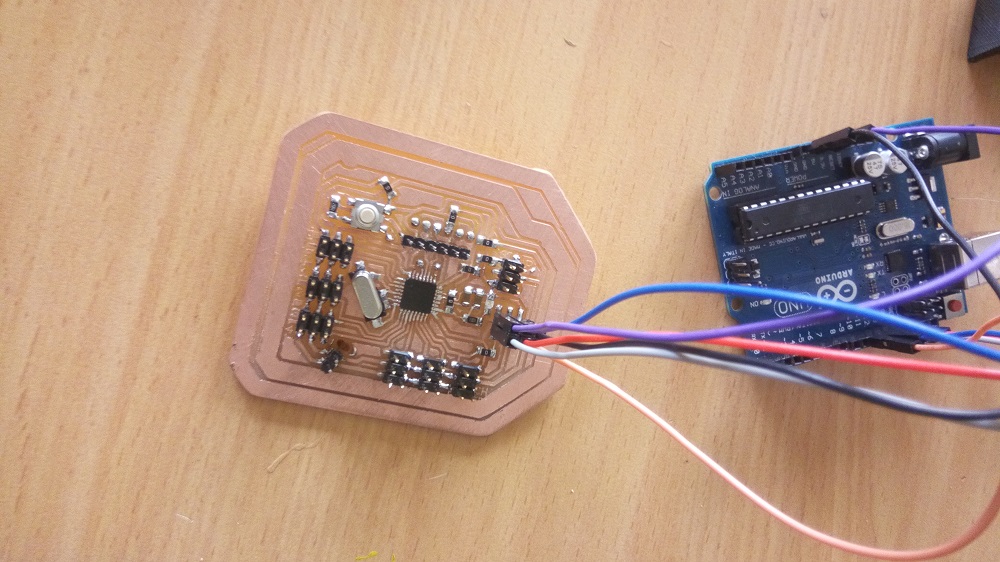
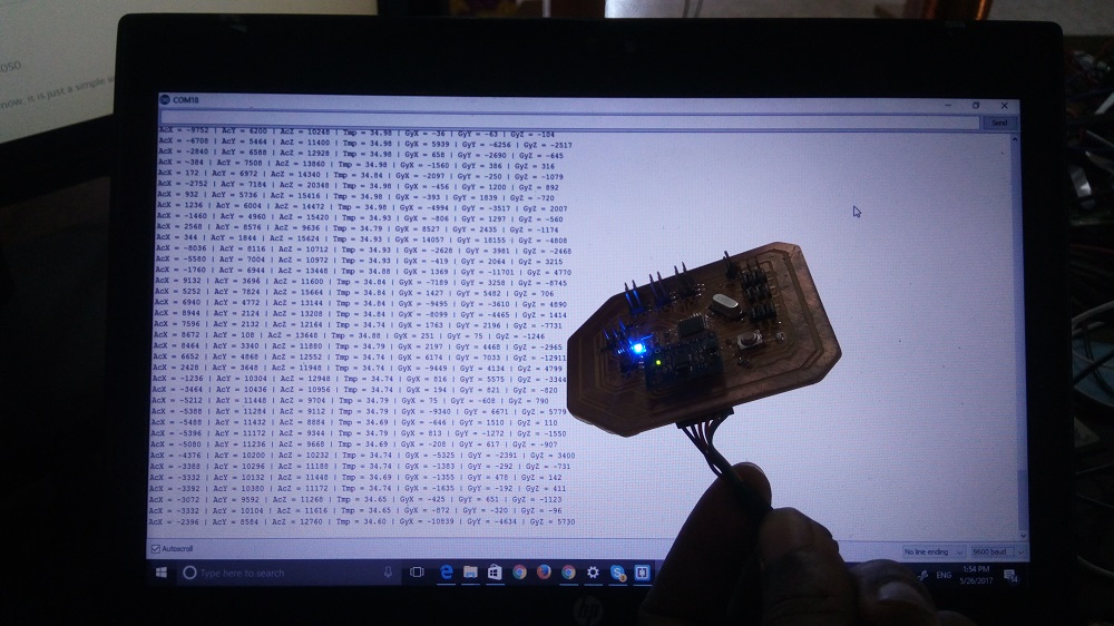
my Board is reading input value well and i hope it will work for my projectDownload files
MPU 6050 CODEPCB BOARD