Group Assignment
10.4.17Machine and Machine Designing
Group Assignment : So much learning and Fun!!
Goal
The goal for this week will be making an XY plotter which can draw on a paper or sketch designs on a sand or make a rangloi. We wanted to make use of the Reprap ramps 1.4 board and an Arduino Mega to kickstart the electronics and give life to our board. Also, we wanted to finish off the board design and documentation in time.
Team Members
Gaurang Shetty
Task: Projection Coordination and Assembling
Amit Yadav
Task: Electronics and testing
Lavina Utamani
Task: Mechanical Design and Calibration
Raj Dhiravani
Task: Documentation and Material Procurement
Brainstorming

We brainstormed about various problem statements / opportunities.
It was discussed that we make a machine which can make sketches using a pen, but later we realised that there are several similar projects.
At riidl fablab we have a autonomous chessboard, which is one of the most advanced chess boards in the world. Seeking inspiration from the same, we decided to make an XY plotter, with the H Bot mechanism.
We decided to make a xy plotter with a mounted pen, which can doodle. Also, we could learn to explore various aspects of Machine designing and programming while making this project.
We all designed all the components and parts and had a clear understanding of what we are making and how we will do it.
H Bot Design

We designed the board on Corel Draw and the part files on Rhino 5
Files attached
Rough Sketch of the concept
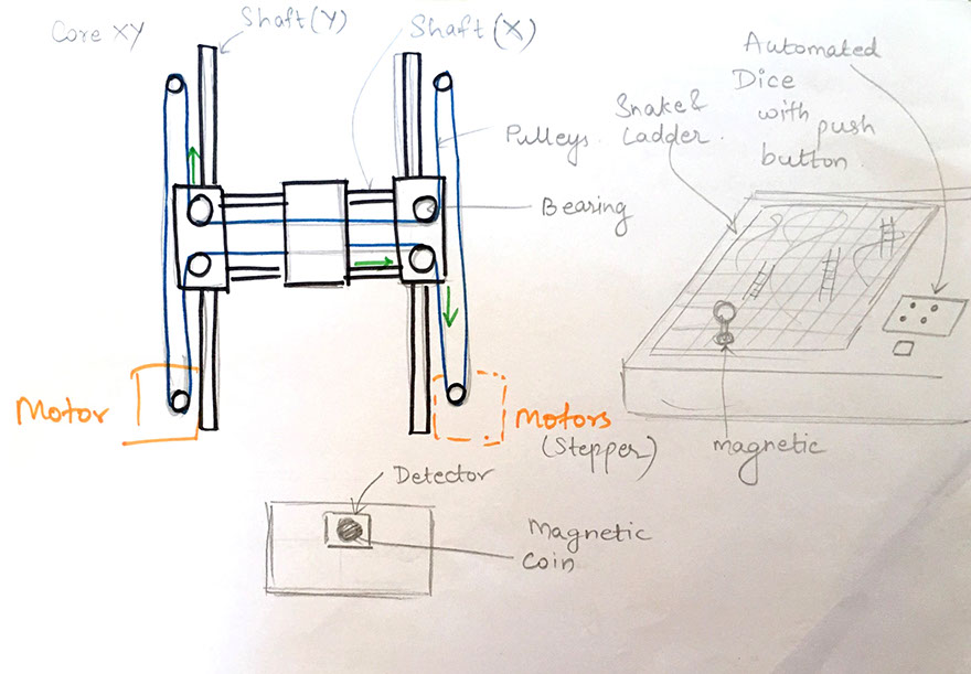
Later we decided to start working as a system and the flow of work is as following: Making a basic design and structure of machine Figuring out the material and components needed Making a 3D model Making a working model of machine Making it automated Final testing and video making
The following parts were listed by the team to start machine building The Chassis design (MDF laser cut) Two precision stepper motors USB motor controller Two machined aluminum winches Crossed roller bearings, brush-lift motor, and cable guide The lower deck with clip for paper USB Cable Universal input plug-in power supply A4 Size paper
Lavina:
I started sketching a design after the brainstorming. I referred several designs online and reading more about the origin of this board game.
We all started sketching the board on a paper and the sketch attached below was the sketch we chose. I later designed the board using corel draw, so I can create the dfx files and cut it in our laser cutting machine.
I used rhyno software to design the board and later 3D printed the mounts.


What did we do?
This week is going to be very crucial as we have to make our machine to come in life and draw shapes with it. We have procured all the materials; it's time to machine, assemble them and test it. To make it happen I did following tasks.
Tweaking firmware
Choice of sensors / Bump switches / motors
Documentation
Designing Motor clamp
Designing mounts and assembling them
We prepared a sheet which has all the bill of Materials. All the materials we brainstormed were available locally in the electronic market in Mumbai (A place called Lamington road).

Gaurang: Project Co-ordination and Assembling
I was coordinating the project. Project coordination stages usually include creating an overall goal for the project, planning essential tasks, executing the project.
Project co-ordination is important to achieve the goals and complete the project on timeline. This includes the communication between the teams to reach the short-term. Project should respect time frame, if not then it will be disastrous project will collapse and the resources will be wasted. To successfully crack reach the goal, it is necessary for the project coordinator have the knowledge of the expertise of every member in team and their skillets. Project Co-ordination Sketching rough models for machine Electronics Design I also, did the assembling and calibration of the board being developed.
We used a CoreXY arrangement for our board. The CoreXY arrangement and the very similar H-bot arrangements are popular mechanical arrangement for a RepRap motion stage. The CoreXY and the H-bot are a Cartesian arrangements -- they makes it easy to move the head in straight lines along axis 90 degrees from the other axis. There is a small change in the belt pattern from the H-bot arrangement to the CoreXY arrangement. Some people say that the CoreXY arrangement is unconditionally better than the H-bot arrangement.
Downloadable file for the xyplotter in .dxf format
Pictures in Action!

Amit: Electronics and testing
I did the 3D printing and starting working on the electronics system of our board. For testing the design (proof of concept) we used an Arduino Mega. Previously we thought of having the machine brain as the controller board designed and the having nodes to communicates with each other to send signals here and there. The terminology of 'stage' means one actuator which results into one more degree of freedom considered as a stage. One stage which moves the access in X direction and other in Y direction for two stage machine. Multiple stages means more complex machine which can handle the very complex jobs. Finding proper firmware for the our board I explored Pronterface which, is a cross platform printer control program that can be used for testing/printing. I designed the PCB and started making the circuit.
I downloaded the original i.e. untouched Marlin from the GitHub and opened it using Arduino IDE. My main task is to tweak the firmware according to my machine and it's sensors and actuators.
When I opened the Marlin.ino file after unzipping the content from I got from the GitHub. Opening Marlin.ino is the collaborative work of plenty of files all together. The most important file that we will be tweaking is the configuration.h, this is the file which contains all the information to run the entire firmware.
I've changed following lines of code present under configuration.h file
Downloadable file for code in .ino format

Lavina: Mechanical Design and Calibration
I started sketching a design after the brainstorming. I referred several designs online and reading more about the origin of this board game. Watching sand art is really soothing and relaxing. I travel a lot and specially, sand, sea, beaches , etc always have fascinated me. This installation will get artist think differently and draw some amazing sketches using sand. I started designing the board using corel draw, so I can create the dfx files and cut it in our laser cutting. I used rhyno software to design the board and later 3D printed the mounts.
I designed the files using Rhino 5 after calculating the part height as per the motor and pulley using Extrude and Boolean functions the parts were created and then saved as stl for 3D printing.
Part1 is designed to fit the linear bearing shaft and X shaft, it measures 50*50*25 and was printed in PLA later
Part2 is designed to fit the Pulley at the corresponding height and it measured 30*50*10
We used FlashPrint we sliced the object and generated g code for the same files
We printed two sets that were required to complete the H Bot Mechanism.


The image below is a Flash Forge 3D printer, which we used.
The Flash Forge 3D printer

3D printing in Action

3D printed stand

The shaft

I also, did the assembling and calibration of the board being developed. We used a CoreXY arrangement for our board.
The CoreXY arrangement and the very similar H-bot arrangements are popular mechanical arrangement for a RepRap motion stage. The CoreXY and the H-bot are a Cartesian arrangements -- they makes it easy to move the head in straight lines along axis 90 degrees from the other axis.
There is a small change in the belt pattern from the H-bot arrangement to the CoreXY arrangement. Some people say that the CoreXY arrangement is unconditionally better than the H-bot arrangement. "A Core-XY Implementation: overcoming H-Bot design drawbacks and building a laser-paper-cut. Other people say that the H-bot arrangement is better than the CoreXY arrangement.
A CoreXY and a H-bot are a parallel manipulator system. In other words, the motors on a CoreXY system or H-bot system are stationary.
Parallel manipulator systems, such as CoreXY and h-bot and Dualwire-Gantry (DW-G), typically have much lower inertia than serial stackup arrangements. The lower inertia of a parallel manipulator system, when using the same motors and the same forces, typically gives more rapid acceleration than serial stackup arrangements.
Raj: Documentation and Material Procurement
I worked on the material procurement for the project. I visited several shops and started purchasing the materials according to the bill of materials. The materials were sourced from lamington road, which is one of the biggest electronic market in Mumbai. Lamington Road is famous for its wholesale and retail market in electronics goods. Shops on the street sell computer goods, electronic items, television equipment, and wireless equipment at rates much lower than the maximum retail price as they have a high turnover. Not only the latest computer related items but even outdated electronic parts for radios like transistors, capacitors, cables, sound cards, TV tuners and adaptors can be bought from this market.
Tweaking firmware
As we have chosen the REPRAP RAMPS 1.4 board, it gave us the advantage of choosing from variety of firmwares available as this is one of the popular board among the 3D printing enthusiasts.
The process of tweaking all started with the tutorials available on youtube. In video he has explained very nicely about the Marlin firmware and how do I tweak it to use with the RAMBO board. Also, he has explored all other options available with Marling.
Click here for checking the reference video!
Reference: Marlin Firmware Instructables
It also has replaceable fuses that protect the board from over-current and allows you to replace them without any soldering required. The design of the RAMBo also allows it to act as a heat dissipater for the stepper motor drivers, which means that there is no need to install a heatsink on the stepper driver chips like many people did for the RAMPS. The design of the RAMBo also ensures that the stepper drivers will never fail and fry as was often the case with the RAMPS.
Reference link Marlin firmware - Instructables
Motherboard ID ==> 301
Motor maximum speed ==> 200 mm/sec
End stop configuration ==> FALSE
Temperature sensor ==> 0 (Not in use)
Max Acceleration ==> 3000
Choice of sensors
Endstops are nothing but the sensors which are used to make sure that machine arm is reached the datum position. If the datum point is not got detected then possibly motor will get burn or the machine's chassis may get heavily damaged as the acceleration-speed as well as mass of the arm will result impact intensity.
To have the simple design I've used the limit switches as the end-stops. Here the switch gets pressed whenever arm hits the leaver of the switch. And when leaver is triggered this sends the notification to the main controller of RAMBO board which is the Atmega2560 with the voltage level.
As we have the sensors to judge the position of the arm or actuator this machines is closed loop control system.
Documentation
I made page to present our machine design group assignment which was made using text wrangler. I made it responsive. "Responsive" means that it can be easy get molded into the desired shape according to the size of the devices. It delivers the best possible UX-UI experience by relocating the objects.
Designing Motor clamp
To hold the motor in place it is designed. I've designed the motor clamp using the acrylic which is widely available in the lab and quite sturdy to take weight of the motor. I've used very simple strategy to design the motor clamp is to have the center hole from where shaft of the motor can come out and four extra holes to tighten the motors using the small screws.
Downloadable file for the servo holder in .dxf format
Designing Bearing Housing
Bearing housing is the necessary for holding the bearings in place with the top arm. We had MDF and acrylic, which was laser cutter friendly and sturdy. So, I designed the U shaped with the hole almost equal to the outer diameter of the linear bearing.
After laser cutting and 3D printing and assembling all the basic parts:


Our first attempt to run the board!
We made a dummy file and loaded it on Pronterface and then we ran this program to see how our XY plotter responded. It did fairly well and replicated the same design on the paper. Our team is super happy and excited!. We will keep improvising this machine and calibrate it to get more accuracy.
Design Files