Assignment 7
8.3.2017
Topic: Make something big (by a CNC machine)
Learning outcomes:
Document the process of design and production to demonstrate
correct workflows and identify areas for improvement if needed.
Have you:
Explained how you made your files for machining (2D or 3D).
Shown how you made something BIG (setting up the machine, using
fixings, testing joints, adjusting feeds and speeds, depth of cut
etc).
Described problems and how you fixed them.
Included your design files and ‘hero shot’ photos of final object.
CAM
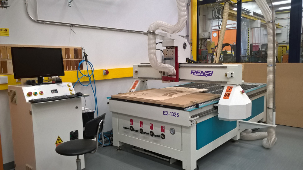
Our CNC router machine is Excitech E2-1325 and control
software Weihong ncStudio.
At first, I liked to test my CAM software, NX11. I knew, I
can do CNC programming with it, but how compatible code is? First
test passed.
Simply, I milled outlines of 100x200 mm test block. I must only
confirm I use mm units and proper values of spindle and feed speeds.
These are following as guideline:
- chip load: ~ 0.025 - 0.25 mm/r (~ 0.001-0.010") =
feed rate (mm per minute) / (RPM x number of flutes)
- cut depth: ~ tool diameter
- step-over: ~ tool diameter/2
Further, big blocks must be fixed firmly by screws, vacuum table or
clamps. Also, holding tabs might be used.
I designed a storage box to my camper car. Here is the sketch of end
blocks I want to mill.
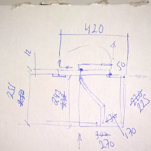
I modeled those outlines by NX11 and made a plan for 3 mm screw
holes I need for fixing parts together. Left one drawing is the
design functioning sketch and the right one the final outline.
Further, I made new hole plan and more carefully. Mainly, I used
Line, Circle and Fillet operations when I modeled.
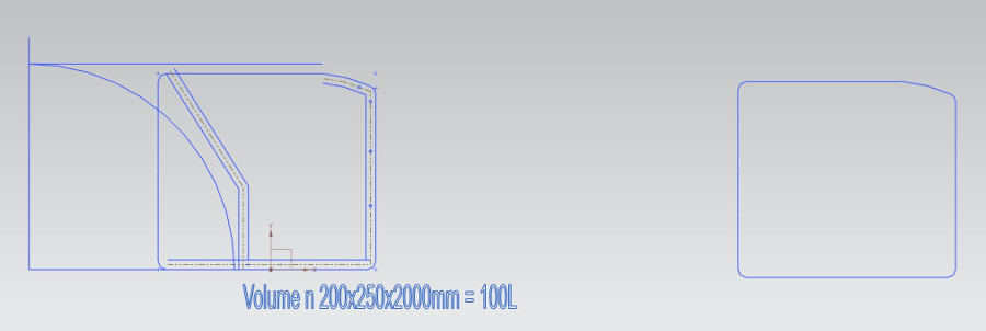
Milling data for router needs only outlines and hole locations. The
second end plate is the mirror of the first.
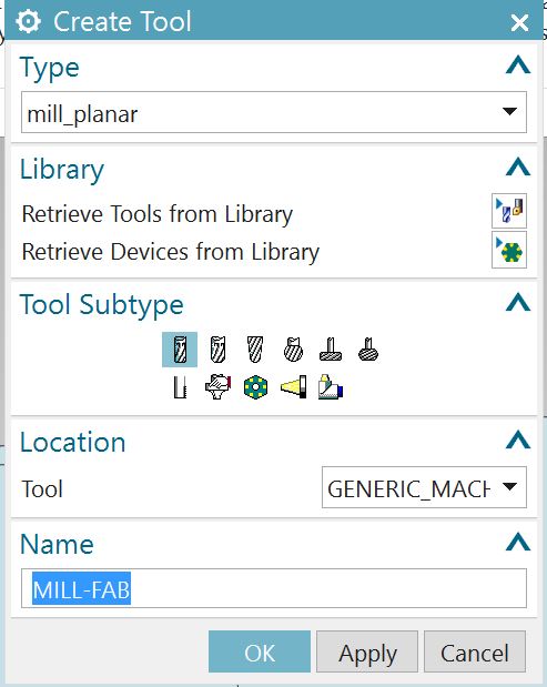
NX11 CAM is an integrated application of the NX 11 CAD software. It
starts from main tab by selection Application >
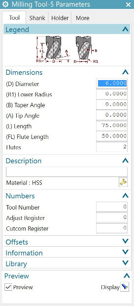
Manufacturing. At first, I created new tools for milling. I used 3
and 6 mm 3-flute flat end bits. Only diameters must be corrected
from defaults.
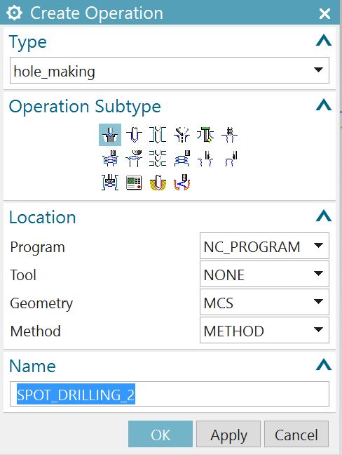
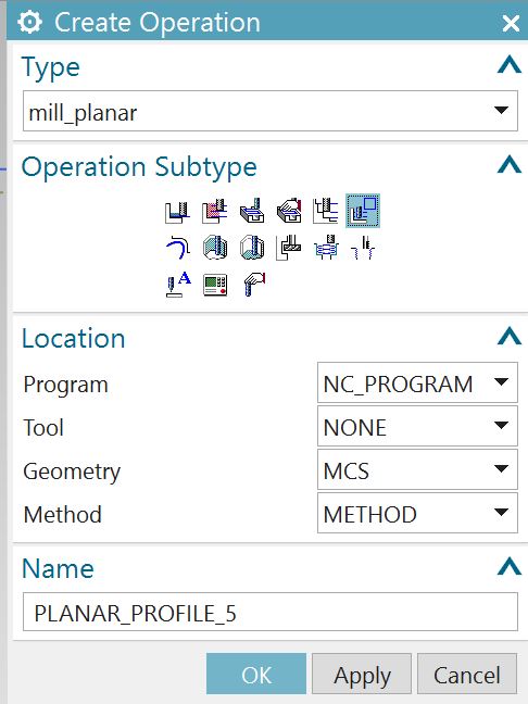
Next step was the operations for drilling and milling. I modeled 3
mm holes by hole_making operation and spot_drilling
subtype.
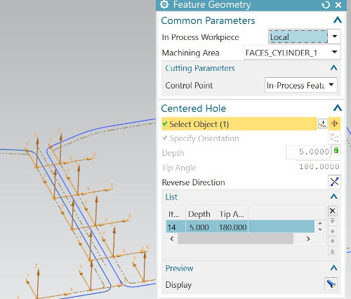
Then, I selected holes from my drawing and generated the drilling
plan. Drilling depth I set to 5 mm from top level of block. I
couldn't set more because of short bit length.
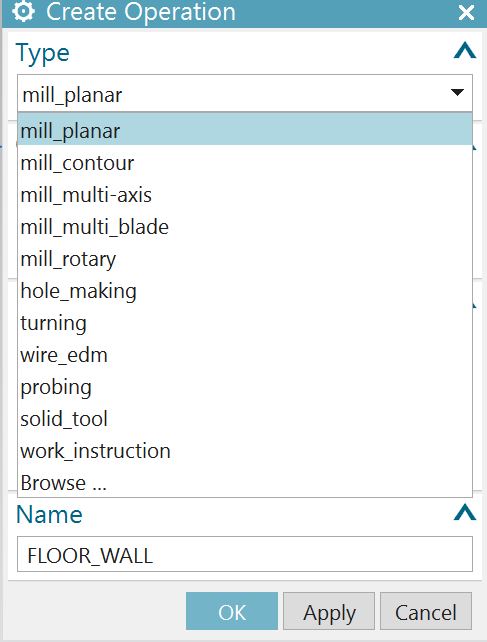
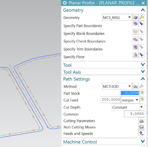
Then, I modeled milling plan by mill_planar operation and planar_profile
subtype.
Only 2D outlines needed to select by Specify Part Boundaries
command.
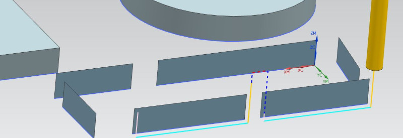
I set Floor to -19.6 mm distance from top of block by Specify
Floor command.
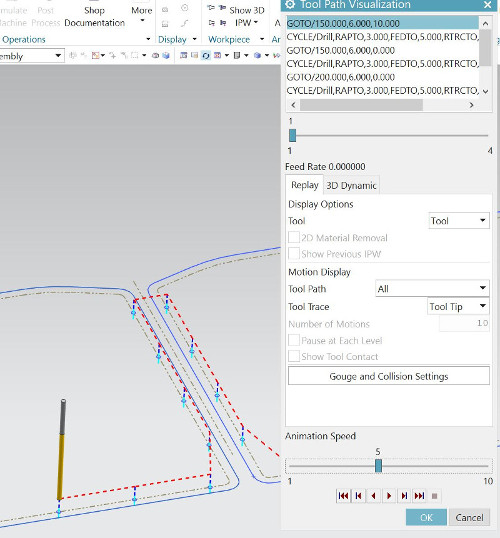
I modeled milling as 3 mm steps downward, left block first
then right block. Red dash line shows the transfer between blocks.
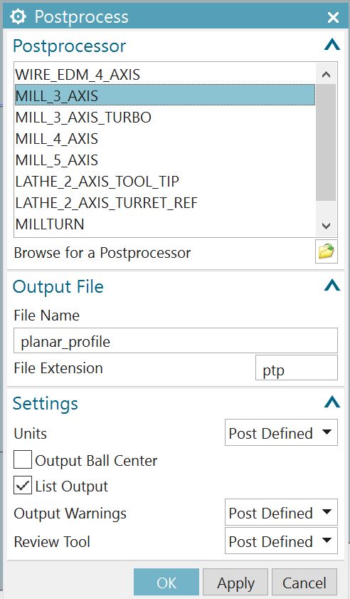
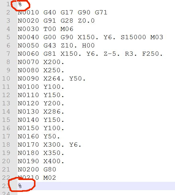
And finally, I used NX11 CAM and general Mill_3_Axis Postprocessor
to generate G-code for router. I only edited % marks out from
code.
I used MDF material. Block thickness was 19.6 mm. I fixed my block
to the milling board by screws, assembled the 3 mm drill bit and
made zeroing to block top level.
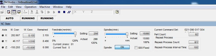
Then, I started the router and Weihong ncStudio software on
the control computer. It did automatic machine calibration. Then, I
set origin on top of my block moving the machine head manually and
using mobile calibrator. I zeroed the work coordinates by
pressing W.Coor buttons accordingly. I can operate the machine in
different modes selecting auto, manual or calibration windows.
Programmed use started on auto mode where I loaded my G-code,
simulated and drove it. I made 3 mm holes first. Then, I
fixed blocks also from these holes and, therefore secured unwanted
motions. I changed bit to 6 mm one and drove outlines also. Both
cases feed rate was 300 mm/min. and spindle speed
15.000 r/min.
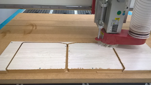
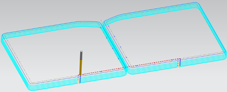
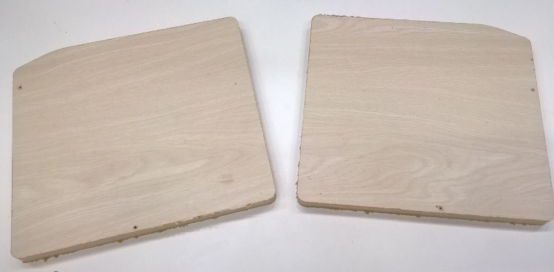
Here are the final blocks.
I studied different strategies to mill parts. I used 3D parts,
cut 2D outlines to several short lines and arcs and
generated milling tracks by them. Therefore, I produced tracks for
outlines and holding tabs from the same geometry.
I made some minor mistakes also. At first, coordinates zero
point was too far from outlines. I created new local coordinates
close to parts. Next, I used 5 mm step downward and I changed it
to 3 mm. And, even block thickness was correct, I done extra
milling to get out the parts. This caused maybe from router error,
error from zero z level calibration we talked later.
My NX CAD file is here: 2D model.
This also in DXF format is here: 2D
model.
Post-registered note:
Following picture presents almost ready-made storage box
for my camper car. The most difficult work was the correct design
of the box. The gray bed plate lifted to the level of back seat
forms a bed with top of storage box. The bed plate is lifted via
curved trajectory from "inside" storage box to the up. Design that
the top plate size, opening and place works well with bed plate is
very important. This idea is presented in sketch and picture at
the beginning of this page.
EU regulation sets bed size to 1800x1200 mm at minimum for camper
cars.
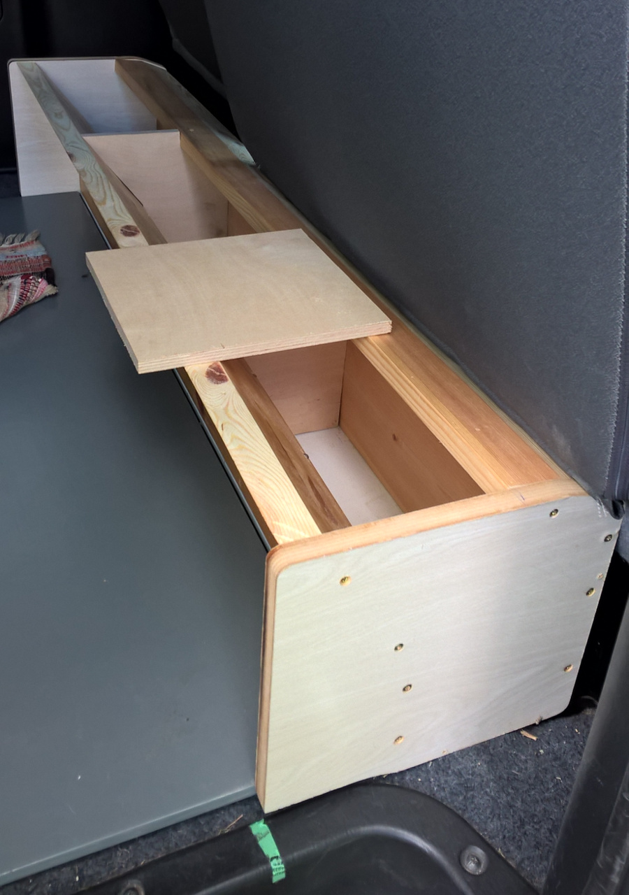
I used Ø4.2x57 mm screws and outdoors-use glue for assembly of
the storage box. Other parts were hand-made using circular saw,
but with help of my CAD/CAM model. Long side material is pine wood
20x140x1220 mm. Inner and top part materials are 12 mm plywood.
Strong and simple joints are very important. Top plate is not
ready yet. Small plywood plate poses it in the picture.